Huda Hashim Mohammed![]() | Ali Fadhil Naser*
| Ali Fadhil Naser*![]() | Lihui Qin
| Lihui Qin![]()
© 2024 The authors. This article is published by IIETA and is licensed under the CC BY 4.0 license (http://creativecommons.org/licenses/by/4.0/).
OPEN ACCESS
The primary goals of this research are to examine the structural appearance of a horizontally curved bridge to identify any damages within the bridge structure, examine its dynamic and static reactions below moving load and service load (load combination) using CSI-Bridge Ver. 25, and to compare the static results with allowable values in the standards to determine the structural state of the bridge. Considering the findings for the appearance inspection, static and dynamic analysis, the bridge's superstructure and substructure did not sustain any damage. The measured values of static responses, such as positive bending moment, negative bending moment, compression stress, vertical deflection, and tensile stress, were found to be below the allowable thresholds in the ASSHTO LRFD-Bridge 2017, implying that the structural stiffness, bearing capacity, and load resistance are adequate, and that downward vertical deflection and cracks are unlikely to occur with structural component parts of the bridge under these types of designed loads. Dynamic research revealed that the dynamic natural frequency was lower than the live load natural frequency, indicating that the bridge structure is in a prolonged state of vibrating due to moving loads.
curved bridge, box girder, moment, stress, deflection, frequency
Currently, building bridges is a global undertaking of great importance. Bridge structure is designed to transport road traffic or other types of moving loads over a barriers or others infrastructures. Bridges are a vital type of civil engineering infrastructure that plays a critical role in facilitating economic activity within a city. Bridges are substantial and robust civil constructions composed of various types of structural elements. There are two groups into which the individuals are categorized. The superstructure comprises bearings, girders (beams), joints, a deck (including walkways), an asphalt surface layer, a drainage system, and a security barrier. The substructure group is on foundations, including piles, pile tops, pier caps, and piers. With civil engineering, bridges are an essential component of the transportation system [1-9].
The box girder type bridge has gained great popularity recently due to its high level of serviceability, stability and structural efficiency. Analytical, experimental or numerical methodologies are necessary to study such a bridge. Analysis of structural actions for due to its complexity, a box girder bridge cannot be thoroughly examined using conventional techniques. A box girder is a structural element consisting of two panels joined together by a shared flange at the bottom and top. According to the construction method, geometric shapes, and purpose, we can classify box girder. The box girder layouts are often used in practical applications. Box girders can be built in three different configurations: single cell, multi-cell, or multi-cell. The hull can be built as a monolithic unit with the deck, also referred to as a closed box girder, or the deck can be built separately and added afterwards, referred to as an open box girder. The box beam is often composed of prestressed concrete, structural steel, or reinforced concrete. Box girders can be classified into rectangular, trapezoidal and circular shapes based on their shape. The box girder section has excellent structural performance, with high torsional rigidity and bending ability. It also provides optimal use of the department and achieves appropriate economic returns [2, 10-14].
Curved bridges can be built using reinforced concrete, prestressed concrete, steel, or a combination of concrete and steel on caissons or steel I beams. Concrete box girders are typically constructed on-site or manufactured in sections and then assembled using shoring or a launching and prestressing method. The platforms can be constructed using steel, reinforced concrete, or prestressed concrete. Historically, bridges with curved alignment were rare, but now most straight bridges have been transformed into curved ones due to factors such as site limitations, architectural considerations, adjustments in speed limits, and traffic volume. The curved box-girder bridge features a cellular cross section that effectively withstands the significant torsional force, resulting in improved efficiency. The curved bridge is renowned for its efficacy, stability, functionality, cost-effectiveness, and attractiveness. Usually, a circular arrangement with transition curves is selected for these. The Bridges with curved designs require more complex analysis than straight bridges because the girders' curvature causes a combination of bending and torsion. Hence, the selection of a section for the construction of a curved bridge should prioritize strong torsional stiffness in order to optimize the section's efficiency [15, 16].
Evaluating a building's or element's structural integrity and capacity to support varied loads is the primary goal of structural analysis, including those resulting from external variables such as support displacement and temperature changes. Structural performance is determined by various variables, such as strains, stresses, axial stresses, shear forces, deflections, support responses, and bending moments. Structural design includes processes for determining shape, calculating weight, and maintaining the balance of structural components and elements. However, it must be ensured that the structure constructed can withstand the specified design constraints and the loads to which it will be subjected. The purpose of conducting theoretical and experimental analysis of the bridge structure is to study the loads on it during regular use, fatigue, and extreme situations. However, the effectiveness of the bridge's performance structural components must be evaluated, and theoretical models must be constructed in order to confirm their validity by comparing them with the results of empirical tests. Field load testing is a fundamental technique used to evaluate the structural integrity of bridges. It also provides a comparison to the bridge between the actual performance and theoretical assumptions under loads. There are two different types of load tests: dynamic load tests and static load tests [17-27].
Haloo and Kafimosavi [24] examined the use of sophisticated, three-dimensional finite-element modeling and analysis to study the flexural behavior of horizontally curved prestressed post-tensioned box bridges. The bridge length, material qualities, and section shape remain constant throughout all models, with the only variation being the degree of curvature, which ranges from 0 to 90°. The analytical results indicate that there are notable differences between the stress distribution of straight and curved bridges. Furthermore, stress level at certain spots within the section width is significantly elevated. The proposal suggests altering the arrangement of the prestressing tendons throughout the breadth of the section to enhance the capacity of the bridge. The suitable redistribution of prestressing within the section width, according to the results, it is possible to achieve a substantial decrease in resultant stress.
Shao et al. [25] explained that two types of damage can occur to traditional long-span prestressed concrete box-girder bridges: numerous cracks in the main girder and significant deflections at the halfway point. In order to achieve this objective, a novel design for a box-girder bridge is suggested, utilizing the distinctive characteristics of reactive powder concrete (RPC). To effectively alleviate torsional warping stresses in the box girder and local stresses in the deck slabs induced by wheel loads, a significant number of diaphragms are incorporated into the suggested design. Furthermore, the diaphragms enhance a shear capacity for webs and enhance a compressive stability for the lower slabs. In addition, the suggested design diverges from the traditional box-girder bridge by combining thinner slabs with partial and unidirectional (longitudinal) external prestressing.
Sennah et al. [26] introduced a technique for calculating the horizontally curved composite single- or multicell box girder bridges' dynamic impact properties when subjected to AASHTO truck loading. Using easily accessible software, the bridges are rendered as three-dimensional structures, and the vehicle is reduced to two-focused going along two circular routes that run parallel to the bending centerline. A comprehensive analysis is performed, examining more than 215 prototypes of curved composite box girder bridges. The key characteristics taken into account are the quantity of cells, lanes, level of curvature, length of arc span, inclination for external steel webs, the top chord and bracing systems' dimensions and quantity, as well as the velocity and placement of the trucks. Findings can assist structural engineers in designing bridges with more reliability and cost-effectiveness, and potentially enhance the load-bearing capability of current bridges to avoid weight restrictions or closures.
Sali et al. [27] examined the effects of varying the radii of curvature on box girders, while maintaining the span, cross-sectional form, and material specifications are consistent. The aim of the parametric tests on curved box girders is to assess how variations in the radius of curvature affect the girders' structural performance. This study aims to increase bridge engineers' comprehension of the structural characteristics of both straight and curved box girder bridges. The study's findings will give bridge designers a great deal of useful information.
This study's primary aims are to assess the horizontally curved bridge's structural safety by detecting damage to its structural elements, analyze the bridge’s acceptance of both moving loads and also the service loads (load group) in terms of static and dynamic performance, and evaluate the structural condition of the bridge by comparing the static results with the values. The phenomenon is permitted and specified in the standards.
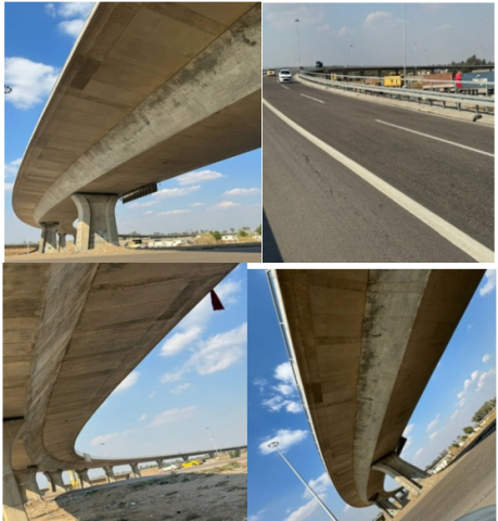
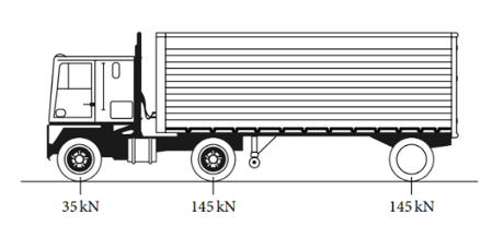
A bridge structure is a posttension concrete horizontal curved box girder bridge. It is located in south of capital of Iraq (Baghdad City) which represent passage of the traffic transmission from Al-Daura-Yusufiyah to Baghdad–Basrah highway. This bridge has 13 spans. The first and thirteen spans have 35m and the others span have 44m in length. The width of bridge is 14m. The number of piers in transvers direction is one (full rectangular pier). the radius of curve is 410m. The dimensions of pier are 2.9m and 1.7m. The structure bridge-constructed was done in 2020 opening was for traffic in 2023. Therefore, it does not suffer from any damage. The compressive strength of concrete is 50MPa. Figure 1 shows the appearance of horizontal curved box girder bridge. The analysis of bridge structures involves the application of five different types of loads. First classification of the dead load is the weight of the bridge itself; it includes the concrete slab pavement layer, precast concrete I-girders, bearings, pier tops, and foundations. The examination of bridge structures is significantly impacted by dead loads. Second classification is the prestressed load, which stands for the tensile force that tendons apply. There are 14 strands in each tendon, and each strand has a diameter of 15.24mm and a cross-sectional area of 140mm2. The steel tendon has a modulus of elasticity of 190kN/mm2. Third classification pertains to motion loads, namely traffic in transit loads caused by vehicles. This study utilizes the HS20-44 vehicle type as the primary live load. Fourth burden pertains to the temperature differential between winter and summer. Wind load is the fifth form of load. Sixth is load combination, which accounts for the combined effect of dead load, live load (traffic load) post-tension load, and wind load, temperature load. Figure 2 shows the box-girder bridge structure finite element model and Figure 3 shows the vehicle HS20-44.
Figure 1. Appearance of horizontal curved box girder bridge
Figure 2. Box-girder bridge structure model: (a) 3D-view; (b) transvers view
Figure 3. Live moving load AASHTO HS20-44 vehicle (28)
The finite element analysis method was used to determine the static forces of a post-tensioned concrete horizontal curved square girder bridge using CSI-Bridge Ver. 25. Three static forces are analyzed and determined in this study. These forces are positive and negative bending moment, tensile and compression stresses, and vertical deflection. These forces give a visible view about the structural conditions of bridge structure. In this study, there are two load cases will be used in static analysis. Firstly, it is live load case which represents the moving vehicles load on the surface of bridge, and secondly, it is loads combination case (service load case) which is devoted the summation of all loads that applied on the bridge structure such as dead load, prestressed load, live load, wind load, and temperature load.
3.1 Positive and negative bending moment
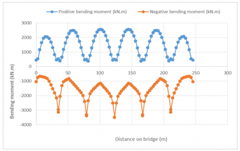
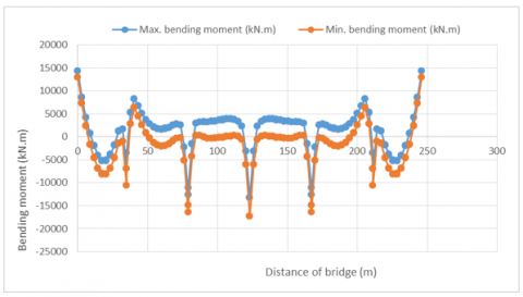
For live load, Figure 4 shows the magnitudes of positive and negative bending moment due to vehicles load. From this figure it can be concluded that the maximum positive bending moment is 2551.56 kN.m which is appeared in the center of span No. 4 and the higher value of negative bending moment is located in the bent No. 3 (support) which is -3506.24 kN.m. Loads combination produces positive and negative bending moment more than vehicle load case. Figure 5 gives the amounts of these moments. the maximum positive bending.
Figure 4. Bending moment under moving load of curved box girder bridge
Figure 5. Bending moment under loads combination load of curved box girder bridge
3.2 Tensile and compression stresses
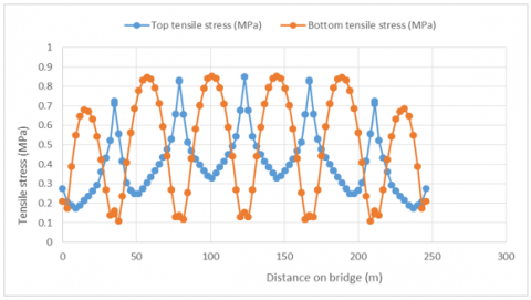
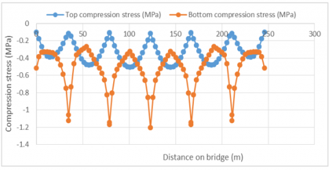
Under vehicles loads, the maximum tensile stress of girder top is 0.849MPa and the maximum value of compression stress is -0.508 MPa. Whereas the bottom of girder appears 0.851 MPa as maximum tensile stress and -1.206 MPa denotes greater compression stress. Agreeing to allowable stress in ASSHTO LRFD-Bridge 2017, the tensile and compression stresses are lower than allowable values of stresses. Therefore, the cracks will not appear in the structure of girders. The allowable stresses are shown below, and Figure 6 and Figure 7 show the values of the compression and tensile stresses for the bottom and top along the bridge length due to vehicles load.
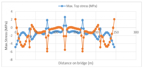
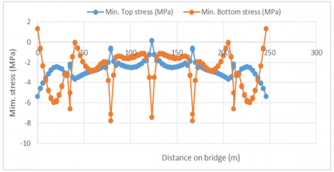
The magnitudes of tensile and compression stresses are illustrated in Figure 8 and Figure 9. In the location near supports, maximum tensile stress magnitude is performed which is 2.59MPa within top of girder which is less than allowable stress (3.53MPa). The maximum compression stress of girder top is -5.37 MPa within the first and end supports of bridge. Bottom of girders provides the maximum value of tensile stress which is equivalent to 2.04MPa and compression stress is -7.08 MPa. These values are fewer than allowable stresses (3.53MPa for tensile stress and 22.5MPa for bottom stress). Therefore, there are needs to deal with posttension position in the supports of bridge (end and start of spans).
For tensile stress = 0.50×√fc=0.50×√50=3.53MPa.
For Compression stress= 0.45×fc=0.45×50=22.5MPa.
Figure 6. Tensile stresses for top and bottom under moving load of curved box girder bridge
Figure 7. Compression stresses for top and bottom under moving load of curved box girder bridge
Figure 8. Tensile stresses under loads combinations load of curved box girder bridge
Figure 9. Compression stresses under loads combinations of curved box girder bridge
3.3 Vertical deflection
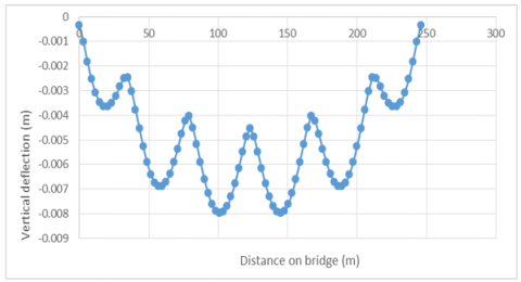
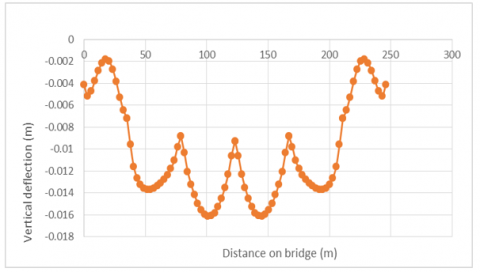
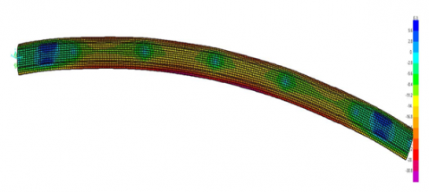
Live load case exhibits -0.0079m vertical deflection in downward deflection within span No.4 which is lower than allowable values in standards (0.055m). Whereas, loads combination case gives -0.0161m higher value of downward deflection in the middle of span No. 3 which is lower than allowable magnitude in the standards (0.036m), indicating that the bridge structure has enough stiffness and loads resistance. Figure 10 and Figure 11 show the vertical deflection under moving load of curved box girder bridge, while Figure 12 and Figure 13 show vertical downward deflection under loads combination of curved box girder bridge.
For live load: ∆= (L of span)/800=44/800= 0.055m
For live load: Max downward deflection = -0.004841 m
Figure 10. Downward vertical deflection under moving load of curved box girder bridge
Figure 11. View of downward vertical deflection under moving load of curved box girder bridge
Figure 12. Downward vertical downward deflection under loads combination of curved box girder bridge
Figure 13. View of downward vertical downward deflection under loads combination of curved box girder bridge
Modal and dynamic analysis methods are depended in this study. Modal analysis method is used to find the modes of deflection for bridge structure when the vehicles pass on the bridge and natural frequency. While, dynamic analysis method is used to calculate the dynamic actions such as live load vibration frequency and vertical dynamic displacement.
4.1 Natural frequency
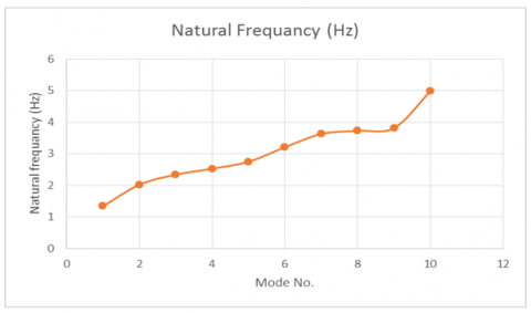
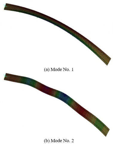
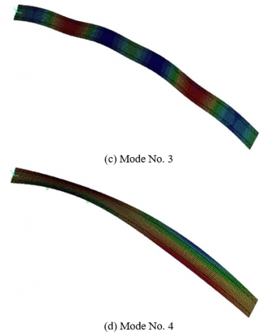
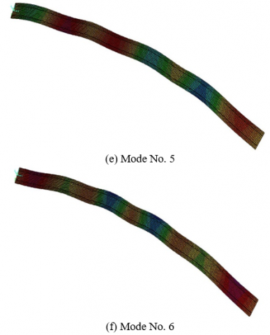
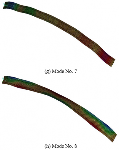
The rate of natural frequency is 2.34Hz from mode No. 3 which has maximum downward vertical displacement. Figure 14 shows the relation between modes and natural frequency and Figure 15 illustrates the modes shape of bridge structure.
Figure 14. Natural vibration frequency values and mode number
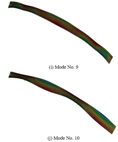
Figure 15. The modes of bridge structure due to modal analysis
4.2 Live load vibration frequency
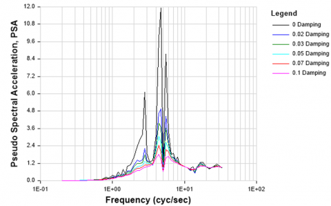
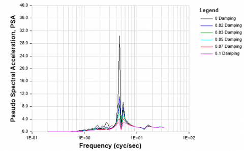
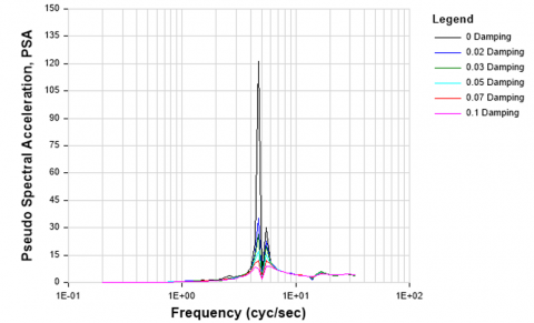
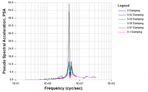
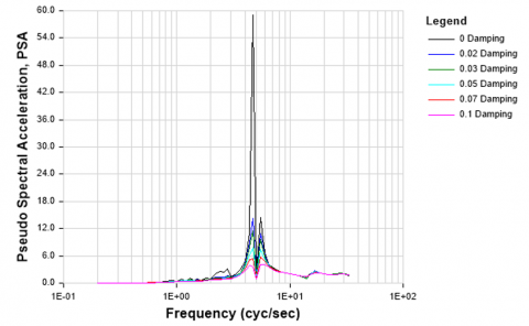
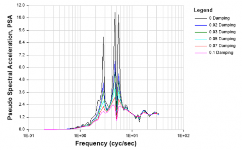
Table 1 lists the magnitude of live load vibration frequency due to moving load which is equal to 4.70Hz. This value is more than the magnitude of natural frequency which is 2.34Hz, indicating that the bridge structure suffers from vibration state with time under vehicles load because of the degree of curvature and super-elevation. Figure 16 shows the relation between live load vibration frequency and dynamic acceleration.
Table 1. The values of loaded vibration frequency for each span
|
Span No. |
Distance of Span (m) |
Distance in Transvers Width (m) |
Joint No. |
Vibration Frequency (Hz) |
|
1 |
17.5 |
7 |
93 |
4.7 |
|
2 |
22 |
7 |
296 |
4.7 |
|
3 |
22 |
7 |
499 |
4.7 |
|
4 |
22 |
7 |
723 |
4.7 |
|
5 |
22 |
7 |
975 |
4.7 |
|
6 |
17.5 |
7 |
457 |
4.7 |
|
Average |
|
|
|
4.7 |
(a) Vibration frequency of middle span No. 1
(b) Vibration frequency of middle span No. 2
(c) Vibration frequency of middle span No. 3
(d) Vibration frequency of middle span No. 4
(e) Vibration frequency of middle span No. 5
(f) Vibration frequency of middle span No. 6
Figure 16. Vibration frequency for bridge model under moving loads
Table 2. The values of dynamic displacement for each span
|
Span No. |
Distance of Span (m) |
Distance in Transvers Width (m) |
Joint No. |
Dynamic Displacement (m) |
|
|
Downward |
Upward |
||||
|
1 |
17.5 |
7 |
93 |
-0.00227 |
0.00102 |
|
2 |
22 |
7 |
296 |
-0.00385 |
0.00139 |
|
3 |
22 |
7 |
499 |
-0.00369 |
0.00186 |
|
4 |
22 |
7 |
723 |
-0.00384 |
0.00114 |
|
5 |
22 |
7 |
975 |
-0.00378 |
0.00149 |
|
6 |
17.5 |
7 |
457 |
-0.00236 |
0.00111 |
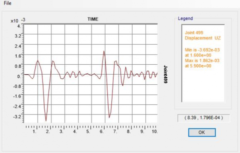
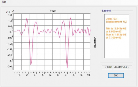
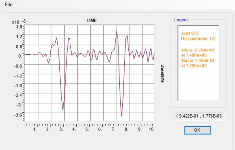
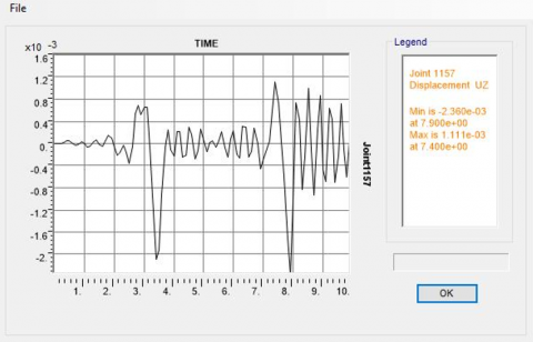
4.3 Live load dynamic displacement
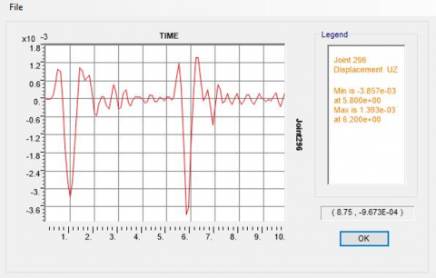
Live load dynamic displacement is a significant component in dynamic analysis because it evaluates the up and down motion of the bridge structure in upward and downward directions under loads from traffic [28]. Table 2 and Figure 17 give the values of dynamic displacement for each span. The higher dynamic displacement in down direction is -0.00385m in the span No. 2 and the maximum upward dynamic displacement is 0.00186m in the span No. 3.
(a) Dynamic displacement of middle of span No. 1
(b) Dynamic displacement of middle of span No. 2
(c) Dynamic displacement of middle of span No. 3
(d) Dynamic displacement of middle of span No. 4
(e) Dynamic displacement of middle span No. 5
(f) Dynamic displacement middle span No. 6
Figure 17. Dynamic displacement for bridge model under moving loads
(1). In this study, the structural appearance of a curved horizontal box girder bridge was examined to determine any damages within the structural members of the bridge. CSI-Bridge Ver 25 was used for the analysis of static and dynamic analysis responses below the movement load and service load (combination load) and to compare the static results with the values allowed in the standards to verify the bridge is in structural condition
(2). The outcomes of the appearance examination of the bridge structure indicated that there were no damages to the superstructure or infrastructure of the bridge.
(3). The statistical analysis revealed that the static values responses, including tensile stress, positive bending moment, negative bending moment, vertical deflection, and compressive stress, were lower than the values permitted in ASSHTO LRFD-Bridge 2017. This led to the conclusion that the structural stiffness, bearing capacity, and loads are satisfactory and that the structural members of the bridge will not exhibit vertical downward deflection or cracks under these types of designed loads.
(4). Dynamic analysis showed that the rate of natural frequency is 2.34Hz from mode No. 3 which has maximum downward vertical displacement. the magnitude of live load vibration frequency due to moving load which is equal to 4.70Hz. This value is more than the magnitude of natural frequency which is 2.34Hz, indicating that the bridge structure suffers from vibration state with time under vehicles load because of the degree of curvature and super-elevation. The higher dynamic displacement in down direction is -0.00385m in the span No. 2 and the maximum upward dynamic displacement is 0.00186m in the span No. 3.
(5). The methodology of this paper, which is included the damage inspection, field tests, numerical static and dynamic analysis of bridge structure, can be applied for assessment of structural performance of each type of bridge (old or new constructed) by adopting damages inspection, static analysis, and dynamic analyses. Seismic resistance of prestressed concrete box girder curved bridge can be evaluated under earthquake action.
[1] Savio, J., Reshma, P. (2017). An overview on box girder bridges. International Research Journal of Engineering and Technology, 4(1): 522-524.
[2] Hussam, M., Ali, F. (2020). Mathematical assessment of vehicles types and loads influences on the structural performance parameters of concrete and steel bridges. Journal of Engineering Science and Technology, 15(2): 1254-1266.
[3] Jaaz, H.A.G., Diwood, N.M., Naser, A.F., Manher, M.F. (2023). Influence of constructing transverse concrete diaphragms in different distances on the dynamic and static behavior of prestressed concrete T-beam bridge structure. AIP Conference Proceedings, 2776(1): 060014. https://doi.org/10.1063/5.0136390
[4] Ali, N., Mohammed, H., Mohammed, A. (2021). Mathematical modeling of linear static and dynamic analysis for pier height effect on the structural performance of bridges structure. Mathematical Modelling of Engineering Problems, 8(4): 617-625. https://doi.org/10.18280/mmep.080415
[5] Ali, F. (2018). Optimum design of vertical steel tendons profile layout of post-tensioning concrete bridges: FEM static analysis. ARPN Journal of Engineering and Applied Sciences, 13(23): 9244-9256.
[6] Naser, A.F., Mohammed, H.A., Mohammed, A.A. (2022). Flexure and shear load rating evaluation of composite bridge superstructure under effect of different trucks load types. Materials Today: Proceedings, 57: 398-407. https://doi.org/10.1016/j.matpr.2021.12.268
[7] Ali, F., Lin, W. (2011). Field damage inspection and static load test analysis of Jiamusi highway prestressed concrete bridge in China. Advanced Materials Research, 163-167: 1147-1156. https://doi.org/10.4028/www.scientific.net/AMR.163-167.1147
[8] Ali, F. (2017). Three-dimensional analysis of girder cross-section shapes effects on static properties of bridges models. Journal of Al-Qadisiyah for Engineering Science, 10(3): 244-258.
[9] Preeti, A., Priyaranjan, P., Pradeep, K. (2022). Box-girder bridges - Modelling and analysis. Engineering Modelling, 35(1): 19-42. https://doi.org/10.31534/engmod.2022.1.ri.02m
[10] Monu, K., Gaurav, T. (2021). Comparative analysis between curved shaped and straight multi cellular box girder with variations in radius of curvature – A review. International Journal of Science, Technology and Management, 8(2): 1-6.
[11] Fadhil, A. Lin, W. (2013). Finite element and experimental analysis and evaluation of static and dynamic responses of oblique pre-stressed concrete box girder bridge. Research Journal of Applied Sciences, Engineering and Technology, 6(19): 3642-3657.
[12] Rishabh, J. Ajit, S. (2016). Curved span PSC box girder bridges: A review. International Research Journal of Engineering and Technology, 3(6): 1437-1442.
[13] Preeti, A., Priyaranjan, P., Pradeep, K. (2023). Finite element analysis of reinforced concrete curved box-girder bridges. Advances in Bridge Engineering, 4(1): 1-21. https://doi.org/10.1186/s43251-023-00080-7
[14] Abdullah, F.W., Aldhalemi, A.A., Naser, A.F., Jaaz, H.A.G. (2024). Field damage inspection and structural performance assessment of precast prestressed concrete I-girder bridge by adopting static analysis. AIP Conference Proceedings, 3092(1): 060018. http://doi.org/10.1063/5.0199598
[15] Richard, J., Shanmugam, N. (2003). Theory and analysis of structures. In Civil Engineering Handbook, Second Edition, Copyrighting by CRC Press LLC.
[16] Aslam, K. (2010). Structural Analysis. Fourth Edition, Copyright 2010 Cengage Learning, Inc. ISBN: 978-0-495-29565-5, USA.
[17] Zhao, J., Liu, T., Wang, Y. (2011). Static test analysis of a bridge structure in civil engineering. Systems Engineering Procedia, 1: 10-15. http://doi.org/10.1016/j.sepro.2011.08.003
[18] James, J., Issam, E., Ching, C. (2006). Performance evaluation of bridges with Structural Bridge Deck Overlays (SBDO). Technical Report No. KTC-06-05/FRT 81-82-97F, Kentucky Transportation Center, University of Kentucky.
[19] Naser, A. (2021). Analysis the effect of super-elevation on static and dynamic properties of horizontal curved concrete bridge by finite element. Journal of Engineering Science and Technology, 16(5): 3669-3686.
[20] Ali, F., Wang, L. (2011). Damage inspection and performance evaluation of Jilin highway double-curved arch concrete bridge in China. Structural Engineering and Mechanics: An International Journal, 39(4): 521-539; https://doi.org/10.12989/sem.2011.39.4.521
[21] Bian, J.P., Wang, Y.L., Li, Y.Y. (2024). Application of thermodynamic models in bridge temperature field simulation and thermal stress analysis. International Journal of Heat and Technology, 42(4): 1317-1326. https://doi.org/10.18280/ijht.420422
[22] Ali, H.M., Najem, M.K., Karash, E.T., Sultan, J.N. (2023). Stress distribution in cantilever beams with different hole shapes: A numerical analysis. International Journal of Computational Methods and Experimental Measurements, 11(4): 205-219. https://doi.org/10.18280/ijcmem.110402
[23] Qin, F.Y., Yang, F.L., Ge, Q.Y., Zheng, J. (2024). Dynamic response of geomaterials considering thermal stress and its application in seismic engineering. International Journal of Heat and Technology, 42(4): 1286-1296. https://doi.org/10.18280/ijht.420419
[24] Haloo, A.R., Kafimosavi, M. (2007). Enhancement of flexural design of horizontally curved prestressed bridges. Journal of Bridge Engineering, 12(5): 585-590. http://doi.org/10.1061/(ASCE)1084-0702(2007)12:5(585)
[25] Shao, X., Pan, R., Zhan, H., Fan, W., Yang, Z., Lei, W. (2017). Experimental verification of the feasibility of a novel prestressed reactive powder concrete box-girder bridge structure. Journal of Bridge Engineering, 22(6): 04017015.
[26] Sennah, K.M., Zhang, X., Kennedy, J.B. (2004). Impact factors for horizontally curved composite box girder bridges. Journal of Bridge Engineering, 9(6): 512-520. https://doi.org/10.1061/(ASCE)1084-0702(2004)9:6(512)
[27] Sali, J., Inqualabi, K.Q., Mohan, R.P. (2015). Parametric study of behaviour of box girder bridges under different radius of curvature. International Journal of Science and Research, 2319: 7064. http://doi.org/10.21275/v5i6.NOV164254
[28] Kuntiyawichai, K., Limkatanyu, S. (2014). Effects of CFRP strengthening on dynamic and fatigue responses of composite bridge. Advances in Materials Science and Engineering, 14: 1-11. http://doi.org/10.1155/2014/784162