Saif Madhat Abd Al Satarr*![]() | Karim Hassan Ali
| Karim Hassan Ali![]()
© 2024 The authors. This article is published by IIETA and is licensed under the CC BY 4.0 license (http://creativecommons.org/licenses/by/4.0/).
OPEN ACCESS
The geometry of wheel-rail contact is a key factor in resolving the dynamics of a rail vehicle. It is generally recognized that the shape used to create both the wheel profile in the rolling region and the railhead has a significant impact on the vehicle's reaction in terms of stability, vibration absorption, and curve-negotiating ability. Analyzing the effects of wheel-rail profile and lateral suspension characteristics on the dynamic hunting stability of rail vehicles moving on tangent tracks is one of the main areas. The railroad vehicle is a multi-body structure that is strongly jumbled, where each multi-body structure has six dynamic degrees of freedom, which correspond to three removals (upward, lateral, and longitudinal) and three rotations (pitch, yaw, and roll). The suspension might be seen as mostly consisting of straight sections for the control method and computation in the plan model. Where the conventional linear railway is converted into a disc rail to ensure the rotation of the rail and thus the movement of the wheels of the cart, the dimensions are taken in miniature form and the reduction rate is 15% compared to the original dimensions of the carriage. The acceleration process is in the form of an increase in hertz supplied to the motor, which thus increases the speed of rotation of the motor. This is observed through the shapes of the axes: the x-axis and the y-axis. The axis X increases in acceleration when the wheels depart the rail because the bogie must rise above the rail. The value of acceleration on this axis reached 60m/s2 and 137m/s2 on the X-axis and Y-axis, which is enough to derail. The speed of rotation of the wheels increased to a speed of 272km/h compared to the old speed of 172km/h.
wheel profile, stability, speed improvement, lateral displacement, and acceleration
A significant component in resolving the dynamics of a rail vehicle is the geometry of wheel-rail contact. It is generally recognized that the shape used to create both the wheel profile in the rolling region and the railhead has a significant impact on the vehicle's reaction in terms of stability, vibration absorption, curve negotiating ability, wheel and rail wear, and ride safety, among other things. The research of vehicle dynamics, on the other hand, is a tough endeavor. Rock-and-roll difficulties develop on tangent rails at slower rates of operation. A car may hunt or bounce a lot at greater speeds. Wheels may mount the rail, excessive lateral pressures may ensue, and rails may roll over when negotiating curving track. Coupling hits in classification yards may cause freight damage. Freight may be harmed by severe vehicle vibrations in over-the-road operations [1]. Understanding dynamic interactions between the track and the train has relied heavily on the approach of mathematically modeling the train and track. Operating circumstances, terrain type, wheel and rail profiles, and climatic conditions all influence dynamic interactions. Building a solitary numerical model that could be generally applied to all components of train-track communications would be troublesome. The refined, unique way of behaving that comes from these associations, then again, might be explored utilizing an assortment of numerical models, every one of which centers around an alternate part of the issue [2]. From a numerical angle, profile improvement can be seen as a straightforward single-objective calculation streamlining issue or a more convoluted multi-objective enhancement issue when mathematical contact and vehicle elements are thought about at the same time, according to the point of view of the vehicle-track compound framework, [3].Where the importance of the research was to find the best profile wheel for the railway that secures the required speed with the least vibration and the highest stability on the track by choosing the best profile for the train wheel. Several researchers have manufactured different wheel profiles, and many tests have been conducted. In 1999, Jaschinski et al. [4] employed roller rigs to research the dynamics of rail cars, and they were especially useful for the creation of high-speed trains. Both full-scale and miniature model roller rigs are taken into account in this assessment. In addition to performance, the most significant experimental studies, the focus on application, scaling techniques for model test rigs, and the variations present in roller rig trials are discussed. In 2000, Dukkipati [5] noted that those insightful investigations are supporting the production of exploratory offices for rail vehicle testing. To coordinate the improvement of the roller rigs and to assemble a scientific structure for the plan and translation of tests to be finished on roller fixes, this work's objective has been to get an understanding of the elements of rail vehicles. The relationship between the American Rail Lines (AAR) model and track test results. Along with logical direct model expectations involving MEDYNA for the hunting execution of a truck on a roller rig. Lead to the conclusion that the roller apparatus would be able and ought to be utilized for truck hunting tests, and the straight hunting model utilizing MEDYNA can be helpful in streamlining the system. In 2002, Bosso et al. [6] modeled a 1/5 scale roller rig to mimic the behavior of a single hanging wheelset and a whole bogie. The best scaling technique is selected for a new roller rig by comparing the various scaling approaches. To forecast the system's dynamic behavior, numerical simulations using multi-body models were used to conduct the comparison. In addition, Mei and Goodall, in 2003 [7], devised an active control method for trains with wheels that can rotate independently. The suggested control structure is adaptable to vehicle speed and has an understandable formulation and simple control structure. Simple guiding measures that are costly and difficult to perform are not necessary. Speed sensors are utilized to screen the relative yaw speed of the wheelset and the body to which they are joined, as well as the overall rotational speed of the two wheels on a similar pivot. The effectively controlled vehicle's bending execution and traveler ride solace stand out from those of a normal inactive vehicle and an optimal control system. Also in 2005, True et al. [8] investigated the dynamics of the Cooper-rider truck moving on a constant-radius curve. Since it is connected to the second issue, we will look at the location of the truck frame and wheelsets while curving. When the critical speed is achieved, we analyze the presence of various stable solutions to the curving problem. One intriguing finding is that there are curve radii for which the critical speed is surpassed when the vehicle negotiates the curve with the permitted maximum cant deficit for a certain superelevation. The critical speed for these tracks is lower than it is for a straight track. In 2006, Michitsuji and Suda [9] advertised the possibility of a guiding bogie that utilizes self-directing while at the same time accomplishing running execution with light dynamic control on a tight bend. An independently turning wheel with an EEF bogie normally has the ability to control itself utilizing the gravity firmness produced by the nonlinear track slope, yet the wheel-guiding movement sways. We can eliminate controlling vibration and accomplish ideal directing with an unobtrusive power help on bends thanks to the proposed power-guiding rail route bogie, which is comprised of freely pivoting wheels with a power-controlling component. The hypothetical examination of the power-guiding bogie and the control plans are talked about in this paper. The viability of the recommended bogie plan and the proposed power-directing control is shown by exploratory discoveries and mathematical recreations utilizing a scaled-model vehicle. At in 2008, Mei and Li [10] offered a design and optimization process for the creation of active primary suspensions and active wheelset controls for stabilization. In a case study, the design technique is applied to a two-axle vehicle, demonstrating the advantages of the novel design approach over other design approaches previously investigated. Also in 2008, Shevtsov et al. [11] developed a method for creating a wheel shape that reduces wear while accounting for rolling contact fatigue to optimize wheel/rail interaction. The method makes use of an RRD (rolling radii difference) function-based optimality criterion. The criterion takes into account safety requirements, minimum wear and contact stresses of wheels and rails, and the stability of a wheelset. While in 2008, Shevtsov [12] studied many issues. First, the geometry of the contact between the wheel and the rail. Then, using contact mechanics, the physical characteristics of the rolling contact between the rail and the wheel are investigated. The dynamics of railway vehicles are then taken into account using the ADAMS/Rail multibody dynamic simulation program. The wheel profile is designed using a numerical optimization process, which is the last step. One design process for a wheel (or rail) profile combines all of these areas. The concept behind the wheel (rail) profile design process is that the wheel/rail contact qualities are largely described by the rolling radius difference (RRD) function. Consequently, a wheel profile that provides the necessary contact qualities specified by this RRD may be found given a known optimum RRD function. Moreover, in 2012, Sedighi and Shirazi [13] examined the bifurcation of rail line bogie conduct within the sight of nonlinearities, explicitly the grating creepage model of the wheel/rail contact, including leeway and the yaw damping powers in the longitudinal suspension framework. The insightful detailing of basic speed and the breaking point cycle recurrence is obtained utilizing the Routh-Hurwitz strength measures and a more exact model than Yang and Ahmadian. Then, at that point, while thinking about the wheel or rail leeway, the plentifulness of the cutoff cycle is figured out utilizing the averaging strategy and logical basic speed. In contrast with the two-pivot bogie model, the discoveries of the one-hub model's basic speed expectation are surveyed for exactness. Moreover, in 2016, Graa et al. [14] investigated freely pivoting wheelsets (IRWs) of shallow-profundity tram frameworks for a sidelong relocation reestablishing force control. With the assistance of singular force control, the bend span might be brought down and the straight-running execution can be improved. Subsequently, the engine's singular force control capacity is the critical figure for close surface travel centers around sidelong dislodging and reestablishing force for the executives driving extreme bends. Trial discoveries with a limited-scale bogie framework affirm the legitimacy and utility of the recommended control strategy. Finally, in 2020, Wang et al. [15] laid out a high-layered solid nonlinear unique model of the great speed vehicle, estimated wheel profile was utilized to describe contact math among haggle, and connection between firmness of the guiding elastic joint and dynamic execution of the rail line vehicle was concentrated on in various wheel and rail wear states. This study analyzed the effect of haggle wear on the powerful execution of the great-speed railroad vehicle in the real-effort process. The discoveries show that when tire and rail wear increments and relating conicity builds, the security of the vehicle's hunting movement, steadiness, and wellbeing all deteriorate. Basic speed, parallel strength, and vehicle wellbeing consistently ascend as longitudinally controlling joint firmness increments. Parallel steadiness and wellbeing frequently stay consistent when the fundamental speed increases by over 17.5MN/m. The basic speed of a vehicle will in general trip first, then, at that point, drop, and in the end will in general be consistent around 5MN/m, which accomplishes its greatest at 2.5MN/m as far as horizontally controlling joint firmness.
The important main equations related to displacement, velocity, acceleration, and others will be used, along with known laws such as the combination of linear Kalker's theory and the derivation of the relationships required at work using the appropriate boundary conditions. This is to reach the highest possible speed without derailing the train with the least vibration, which will be indicated by the lateral displacement and the pitch rotational motion shown in the equations.
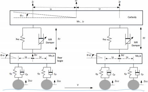
Track highlights have been considered aggravation contributions to the framework, while the vehicle is only considered as far as the bounce and pitch movements, accepting inflexible body movement for the vehicle. Utilizing best-in-class suspension arrangements, a vehicle with a semi-dynamic suspension framework was utilized to evaluate the viability of the recommended control strategy [16]. The benchmark and reference case for assessing the proposed plan are the semi-dynamic suspensions of a vehicle, which comprise a spring and a damper and have a set damping rate, as delineated in Figure 1.
Figure 1. Schematic representation of the semi-active in vertical secondary suspension system
The following is a list of the railway vehicle's governing equations of motion. The following equation describes how a vehicle moves in a vertical direction:
$\ddot{z} v=\frac{1}{m_v}\left[-K_{e q}(z f-z b f)-f M R . f-K_{e q}(z r\right.-z b r)-f M R . r]$ (1)
The equation of vehicle motion for pitch is:
$\ddot{\theta}_v=\frac{1}{\mathrm{~J}_v}\left[-K_{e q} l_t(z f-z b f)-l t f M R . f+(z r-\right.z b r)+l t f M R . r]$ (2)
The equation for the bogies can be formed likewise and comparatively for the rear bogie. For the front bogie:
$\ddot{z_{b f}}=\frac{1}{\mathrm{~m}_b}\left[\mathrm{k}_{e q}\left(\mathrm{z}_f-\mathrm{z}_{b f}\right)+f_{M R . f_{-}} c_{p r}\left(z_{\dot{b} f 1}-\right.\right.\left.\left.z_{\dot{t} 11}\right)_{-} k_p\left(z_{b f 1}-z_{t 11}\right) \_c_{p r}\left(z_{\dot{b} f 2}-z_{\dot{t} 12}\right)_{-} k_p\left(z_{b f 2}-z_{t 12}\right)\right]$ (3)
$\ddot{\theta}_{b f}=\frac{1}{\mathrm{j}_b}\left[-c_{p r} l_b\left(z_{b f 1}^{\cdot}-z_{t 11}^{\cdot}\right)-k_p l_b\left(z_{b f 1}-z_{t 11}\right)\right.+c_{p r} l_b\left(z_{b f 2}^{\cdot}-z_{t 12}^{\cdot}\right)\left.+k_p l_b\left(z_{b f 2}-z_{t 12}\right)\right]$ (4)
For the rear bogie:
$\ddot{z_{b r}}=\frac{1}{\mathrm{~m}_b}\left[\mathrm{k}_{e q}\left(\mathrm{z}_r-\mathrm{z}_{b r}\right)+f_{M R \cdot r_{-}} c_{p r}\left(z_{b r 1}^{\cdot}-\right.\right.\left.\left.z_{t 21}^{\cdot}\right) \_k_p\left(z_{b r 1}-z_{t 21}\right) \_c_{p r}\left(z_{\dot{b r} 2}-z_{t {\dot{22}}}\right) \_k_p\left(z_{b r 2}-z_{t 22}\right)\right]$ (5)
$\ddot{\theta}_{b r}=\frac{1}{\mathrm{j}_b}\left[-c_{p r} l_b\left(z_{b r 1}^{\cdot}-z_{t 21}^{\cdot}\right)-k_p l_b\left(z_{b r 1}-z_{t 21}\right)\right.+c_{p r} l_b\left(z_{b r 2}^{\cdot}-z_{t 22}^{\cdot}\right)\left.+k_p l_b\left(z_{b r 2}-z_{t 22}\right)\right]$ (6)
where, $f_{M R . f}$ and $f_{M R . r}$ are semi-active dynamic damping forces at the front and rear of rear bogie which are MR dampers, respectively, Table 1. In these equations from 1 to 6, are the vertical leading and trailing wheelsets, which are also the track inputs to the system.
Table 1. Vehicle parameters of the vertical model
|
Symbols |
Description |
|
$m_v$ |
Mass of the vehicle kg |
|
$J_v$ |
Body pitch inertia kgm2 |
|
$m_b$ |
Mass of the bogie Frame kg |
|
$i_b$ |
Bogie frame pitch inertia kgm2 |
|
$l_t$ |
The semi-longitudinal spacing of the secondary suspension m |
|
$l_b$ |
The semi-longitudinal spacing of the wheelsets m |
|
$k_P$ |
Primary spring stiffness per axle MNm-1 |
|
$c_{Pr}$ |
Primary passive damping per axle kNsm-1 |
|
$c_{rz}$ |
Secondary passive damping per bogie kNsm-1 |
|
Z |
displacement |
|
$Z_f$ |
$Z_f=Z_v+l_t.\sin \left(\theta_v\right)$ |
|
$Z_v$ |
Vertical displacement |
|
$\theta_v$ |
Pitch rotation |
|
$Z_r$ |
$Z_r=Z_v-l_t.\sin \left(\theta_v\right)$ |
The rail structure is manufactured using a CNC machine, and as a result of the train movement that needs a long track for the train to run, the conventional linear train rail is converted into a disc rail to ensure the rotation of the rail and thus the movement of the cart wheels. In this research, the train was installed above the moving rail, which is linked to a rotating device. In addition, as shown in Figure 2. to ensure the train’s rotation in the same place and because of the large size of the train. Therefore, the dimensions were taken in miniature form in order to facilitate the control of the train. Therefore, the model of the train used in the research was reduced at a rate of 15% compared to the dimensions of the original train.
4.1 Motor
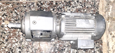
Where a three-phase motor was used and converted to a two-phase motor because the Hertzian device works in two-phase and the motor works in three-phase, and the Hertz modulation device was connected of the motor because changing the Hertz works to change the rotational speed of the motor as shown in Figure 3, and therefore, His ability to change his speed on demand. Where the speed of this motor is at 50Hz, 350rpm with the gearbox engaged with a torque force of 0.75hours, and thus it reaches a speed of 700rpm when it is at 100Hz, as shown in Figure 4.
Figure 2. Structure of rail and train
Figure 3. Motor
Figure 4. Hertz modulator
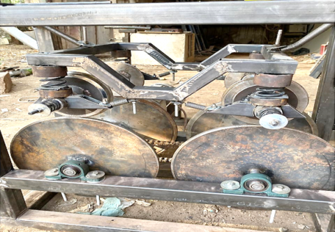
Figure 5. Bogie structural
4.2 Bogie structural
The suspension areas are among the most important parts of the structure, where steel was used with a square section of 3 cm in height, 3cm in width, and 2mm in thickness, and this is what was obtained from the local market after reducing the real size by 15%, where the structure was built as in Figure 5.
4.3 Measurements system
The measuring devices include a scale to determine the true speed at which the failure occurs as well as the amount of vibration that occurs because of this speed, by connecting the Arduino UNO sensor to the body of the train on the one hand and knowing the results from the computer on the other hand.
4.3.1 Arduino UNO
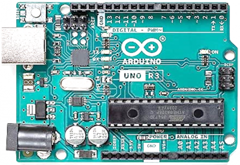
It is a device used as a control brain that is programmed by the computer. It receives signals from sensors and displays them in the form of numbers on the computer, as shown in Figure 6.
Figure 6. Arduino UNO
4.3.2 IR proximity sensor descriptions
Line follower robots and obstacle avoidance robots can identify lines and adjacent objects with the Multipurpose Infrared Sensor accessory. The sensor detects reflected light from its own infrared LED to function. It can detect light or dark (lines) or even things right in front of it by measuring the quantity of reflected infrared radiation. To signal the existence of an item or detect a line, an inbuilt red LED is employed. With an internal variable resistor, the sensing range may be adjusted. The microcontroller board or Arduino board is connected to the sensor's 3-pin header using female-to-female or female-to-male jumper wires. a mounting hole for the front or rear of your robot's chassis that makes it simple to attach one or more sensors.
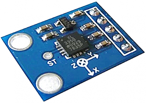
4.3.3 Accelerometer sensor
The ADXL345 is a small, thin, ultralow-power, 3-axis accelerometer that has outstanding resolution and can detect acceleration up to 16g. (13 bits). The 16-bit twos complement digital output data is accessible via an SPI (3-or 4-wire) or I2C digital interface. The ADXL345 is ideal for applications on mobile devices. In tilt-sensing applications, it monitors the static acceleration of gravity as well as the dynamic acceleration brought on by motion or shock. Measurement of inclination variations smaller than 1.0° is possible because of its high resolution (3.9mg/LSB). There are many unique sensing features offered. Activity and inactivity sensing compare the acceleration on any axis with user-defined criteria to determine whether motion is present or absent. Single and double taps are picked up by tap sensing in any direction. The presence of a fall is detected using free-fall sensing. Each of these functions may be assigned to one of the two-interrupt output pins. To reduce host processor activity and system power consumption, data may be stored using an integrated memory management system with a 32-level "first in, first out" (FIFO) buffer. Low power modes provide threshold detection and active acceleration measurement with intelligent motion-based power management at very low power consumption, like Figure 7.
Figure 7. Accelerometer sensor
Where two sensors of this type are used, one at the front of the body and another at the back, and they are used to measure vibrations in the three axes.
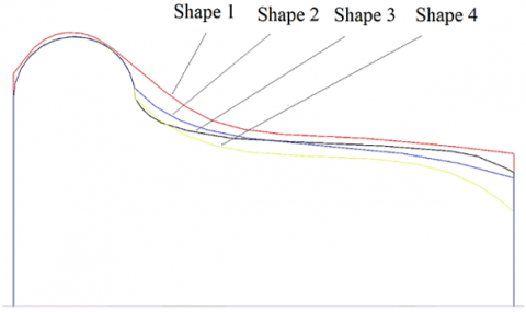
The mechanism of the experimental work is to know the amount of speed that can be reached without derailing the railway by changing the shape of the wheels as shown in the Figure 8. On the experimental side, the speed of rotation of each of the wheels and the rail was also measured, as were the values of vibration from the beginning of the movement until reaching the state of failure.
Figure 8. Wheel shapes
5.1 Shape 3 result
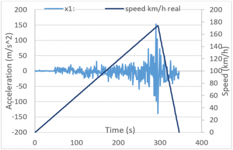
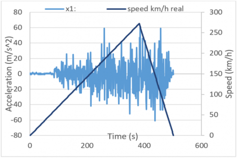
Through the experiment with the original shape of the manufacturer, it was shown in Figures 9 and 10 that the value of the vibration began to increase until reaching a real speed equivalent to 174km/h, where the test process began until the bogie began to derail at the time of 284s from the start of the test at X-axes and Y-axes. The acceleration process is in the form of an increase in hertz supplied to the motor, which thus increases the speed of rotation of the motor.
Figure 9 gives a clear indication of the forward-backward movement, which is known as the pitch movement, as the acceleration in this axis reached 150m/s2 during the bogie’s exit from the rail.
Figure 9. Acceleration of the X-axis vibration sensor at the rear of the bogie with time
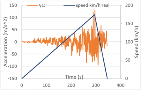
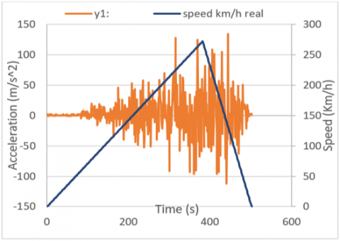
Figure 10. Acceleration of the Y-axis vibration sensor at the rear of the bogie with time
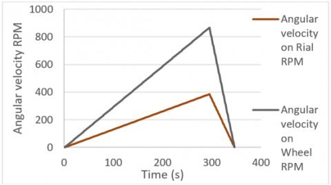
Figure 11. Angular velocity at rail and wheel with time
As for Figure 10 the vibration of the movement from one side to the other defines it, which is roll. Where this movement is necessary to know the wheels in the event of their derailment. At the same speed that the bogie reached, the value of acceleration on this axis reached 134m/s2, which is enough to derail.
Figure 11 shows the difference in the rotational speed of the wheels and the rail itself and the limit of reaching the point where the wheels depart from the rail. The rotational speed reached 866 RPM at the wheels, while at the rail it reached 389 RPM.
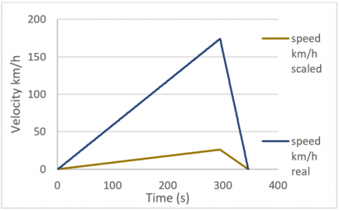
The speed of movement of the bogie follows the rotation of the wheels and the rail according to the diameters used in the experiment. Figure 12 shows the difference between the 15% scaling rate that was used, as the speed reached 28km/h, but in the actual measurement it reached 174km/h.
Figure 12. Velocity at scaled 15% and real dimension with time
5.2 Shape 1 enhanced result
Figures 13 and 14 from the experiment of the enhanced shape demonstrates how the value of the vibration increased during the test procedure until the bogie started to derail 382 seconds after the test started, when it reached an actual speed comparable to 272km/h. The motor's supply of Hertz is increased as part of the acceleration process, which also causes the motor's rotational speed to rise. Where a clear improvement was observed in terms of the ability of the wheels to continue moving at high speeds without deviating from the track, where exceeded speed the old wheel's which was limited of 174km/h.
Figure 13. Acceleration of the X-axis vibration sensor at the rear of the bogie with time
Figure 14. Acceleration of the Y-axis vibration sensor at the rear of the bogie with time
As the acceleration in this axis reached 60m/s2 during the bogie's release from the rail, Figure 13 clearly illustrates the forward-backward movement, also known as the pitch movement. This gives a clear understanding of the stability of the new wheel shape.
Figure 14 is characterized by the roll, which is the vibration of the movement from one side to the other. This movement is required to identify the wheels in the event of a derailment. The acceleration in this axis reached 137m/s2 at the same speed as the bogie, which is sufficient to cause a derailment.
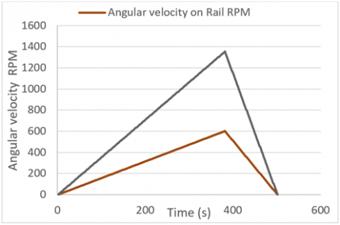
Figure 15 illustrates the difference in rotational speed between the wheels and the rail as well as the distance that may be traveled before the wheels leave the rail. At the wheels, the rotational speed was 1370 RPM, while at the rail, it was 600 RPM.
Figure 15. Angular velocity at rail and wheel with time
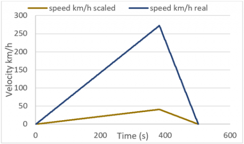
Figure 16. Velocity at scaled 15% and real dimension with time
Depending on the diameters employed in the experiment, the bogie moves at a speed that corresponds to the rotation of the wheels and the rail. Figure 16 illustrates the discrepancy between the speed measured at 272km/h and the 40km/h speed that was calculated using a 15 percent scaling rate.
5.3 Comparison between the original and the improved shape
After completing the inputs to the ANSYS program that were experimentally obtained through the examination. The mechanism of the experiment in improving the ability of the wheel to reach high speeds without derailing at limits 272km/h, where it was increasing the hertz of the motor in an upward manner until reaching high speeds that are sufficient to remove the wheels from the rails, comparison to the old speed that 174km/h.
Figure 17 shows the increase in the speed of rotation of the wheels up to a speed of 272km/h compared to the old case. The increase in the time of acceleration was observed with the stability of the wheels without departing from the track.
Figure 17. Comparison between the original and the improved shape
[1] Santamaria, J., Herreros, J., Vadillo, E.G., Correa, N. (2013). Design of an optimised wheel profile for rail vehicles operating on two-track gauges. Vehicle System Dynamics, 51(1): 54-73. https://doi.org/10.1080/00423114.2012.711478
[2] Mohan, A. (2003). Nonlinear investigation of the use of controllable primary suspensions to improve hunting in railway vehicles. Doctoral Dissertation, Virginia Tech.
[3] Liu, B., Mei, T.X., Bruni, S. (2016). Design and optimisation of wheel-rail profiles for adhesion improvement. Vehicle System Dynamics, 54(3): 429-444. https://doi.org/10.1080/00423114.2015.1137958
[4] Jaschinski, A., Chollet, H., Iwnicki, S., Wickens, A., Würzen, J. (1999). The application of roller rigs to railway vehicle dynamics. Vehicle System Dynamics, 31(5-6): 345-392. https://doi.org/10.1076/vesd.31.5.345.8360
[5] Dukkipati, R.V. (2001). Lateral stability analysis of a railway truck on roller rig. Mechanism and Machine Theory, 36(2): 189-204. https://doi.org/10.1016/S0094-114X(00)00017-3
[6] Bosso, N., Gugliotta, A., Somà, A. (2002). Comparison of different scaling techniques for the dynamics of a bogie on roller rig. Vehicle System Dynamics, 37(sup1): 514-530. https://doi.org/10.1080/00423114.2002.11666259
[7] Mei, T.X., Goodall, R.M. (2003). Practical strategies for controlling railway wheelsets independently rotating wheels. Journal of Dynamic Systems, Measurement, Control, 125(3): 354-360. https://doi.org/10.1115/1.1592191
[8] True, H., Hansen, T.G., Lundell, H. (2005). On the quasi-stationary curving dynamics of a railroad truck. In ASME/IEEE Joint Rail Conference, 37521: 131-138. https://doi.org/10.1115/RTD2005-70053
[9] Michitsuji, Y., Suda, Y. (2006). Running performance of power-steering railway bogie with independently rotating wheels. Vehicle System Dynamics, 44(sup1): 71-82. https://doi.org/10.1080/00423110600867416
[10] Mei, T.X., Li, H. (2008). Control design for the active stabilization of rail wheelsets. Journal of Dynamic Systems, Measurement, and Control, 130(011002-1). https://doi.org/10.1115/1.2807062
[11] Shevtsov, I.Y., Markine, V.L., Esveld, C. (2008). Design of railway wheel profile taking into account rolling contact fatigue and wear. Wear, 265(9-10): 1273-1282. https://doi.org/10.1016/j.wear.2008.03.018
[12] Shevtsov, I.Y. (2008). Wheel/rail interface optimisation. Published and Distributed Section of Road and Railway Engineering Faculty of Civil Engineering and Geosciences Delft University of Technology P.O. Box 5048, 2600 GA Delft the Netherlands.
[13] Sedighi, H.M., Shirazi, K.H. (2012). Bifurcation analysis in hunting dynamical behavior in a railway bogie: Using novel exact equivalent functions for discontinuous nonlinearities. Scientia Iranica, 19(6): 1493-1501. https://doi.org/10.1016/j.scient.2012.10.028
[14] Graa, M., Nejlaoui, M., Houidi, A., Affi, Z., Romdhane, L. (2018). Modeling and control of rail vehicle suspensions: A comparative study based on the passenger comfort. Proceedings of the Institution of Mechanical Engineers, Part C: Journal of Mechanical Engineering Science, 232(2): 260-274. https://doi.org/10.1177/0954406216682542
[15] Wang, Q., Cui, T., Shi, J., Sang, H. (2020). Study on the evolution of dynamic performance of high-speed EMU after long-term service. In IOP Conference Series: Materials Science and Engineering. IOP Publishing, 780(6): 062027. https://doi.org/10.1088/1757-899X/780/6/062027
[16] Hammood, H. (2018). Improvement of semi-active control suspensions based on gain-scheduling control. University of Salford (United Kingdom).