Saif Madhat Abd Al Satarr*![]() | Karim Hassan Ali
| Karim Hassan Ali![]()
© 2023 IIETA. This article is published by IIETA and is licensed under the CC BY 4.0 license (http://creativecommons.org/licenses/by/4.0/).
OPEN ACCESS
The burgeoning demand for higher train speeds, coupled with the pressing need to address train derailments and vibration-induced damage to freight and passengers, necessitates an expansion in design considerations. The ideal wheel shape for efficient and comfortable transportation of people and goods is central to these considerations. This study introduces a methodology for representing any wheel profile via a general mathematical equation encompassing several parameters. This equation is capable of generating any wheel profile based on the chosen parameter values, facilitating the iterative creation of wheel profiles aimed at fulfilling specific objectives. Four mathematical models were constructed using the SolidWorks program, and their characteristics were incorporated into a numerical solution representing the train's mass and the spring and damper attributes. These elements were coupled using the ANSYS program. The ensuing wheel profile's mass and volume, along with the corresponding directional deformation results, denoted by equivalent stress, were ascertained. The influence of mechanical characteristics on the numerical solution's outcomes was evaluated, and the numerical findings were subsequently compared. The results were particularly promising; the speeds for the original shape, shape 1, shape 2, and shape 4 were 160km/h, 267km/h, 243km/h, and 76km/h, respectively. Notably, shape 1, which achieved the highest speed, displayed a reduction in pressure and deformation. This study proposes a novel wheel design that can enhance speed without compromising comfort and stability. The designed wheel demonstrates the capability to maintain its course on the rail at high speeds while causing fewer vibrations, thereby ensuring a smoother ride.
wheel profile, stability, speed improvement, deformation, stress, numerical analysis and hunting phenomena
The escalating demand for expedited railway transportation, catalyzed by the urgency for rapid delivery of both individuals and commodities, underscores the necessity for advancements in this domain. This study addresses the imperative for meticulous railway wheel design, spotlighting the optimal wheel profile as instrumental in meeting the growing need for safety and comfort. The novelty of this research resides in its engineering approach to an ideal design, striving to determine the optimal wheel configuration that alleviates vibration caused by high-speed railway movement, thus enhancing comfort and ensuring safety.
The phenomenon of hunting, a prevalent instability in railway vehicles, forms the crux of our investigation. This oscillatory interaction, triggered by the forward speed of the vehicle and the wheel-rail force, emerges from the conicity of the wheel-rail shape and the friction-slip properties inherent to the wheel-rail contact dynamics [1]. The interaction significantly modifies the damping properties of railway vehicle systems, resulting in hunting oscillations associated with two critical velocities.
The first velocity manifests at lower speeds and is characteristic of vehicles with suboptimal suspension system configurations. Predominantly, this is generated by extensive lateral oscillations (inclusive of yaw and roll) of the vehicle body, akin to a resonance situation. This can be managed by appropriate elevation of the vehicle body and truck frames [1].
In the realm of transportation technologies, the facets of paramount importance are passenger comfort and safety. Road vehicles, while extensively utilized for long-distance travel, frequently encounter diverse external conditions. These disturbances can precipitate undesirable vibrations and oscillations, culminating in mechanical issues, compromised safety, and passenger discomfort [2].
The geometrical problem in the wheel-rail system is contingent upon the cross-sections of the railway wheel and rail, collectively referred to as "profiles" [3]. The design of these profiles has historically reled on engineering expertise, though the advent of computer technology has introduced refined methodologies for profile creation and optimization [3].
An examination of the literature reveals extensive research dedicated to the development and testing of various wheel profiles. Illingworth [4], in 1986, probed the primary performance aspects of suspension systems and wheel profiles in railway vehicles. Jaschinski et al. [5], in 1999, utilized roller rigs to investigate the dynamics of rail vehicles, demonstrating their utility in designing high-speed trains. The assessment under consideration incorporates both full-scale and miniature model roller rigs, with an emphasis on their application, performance, and the variations inherent to roller rig trials. Of particular interest are the scaling techniques employed for model test rigs, and the significant experimental studies conducted using these platforms.
In 2001, a numerical model of a roller rig was proposed by Bruni et al. [6] for comprehensive full-scale inspection of a railway wheelset. This model was devised with the aim of correlating mathematical findings with experimental ones, obtained under controlled and stable conditions. It is expected to provide crucial insights into wheel-rail contact behaviour and wear processes, thus facilitating optimal utilization of the testing facility. Comprising two firmly attached wheels of 2000mm diameter and two UIC-69 profiled rail rings, the roller rig is powered by a direct current engine.
Subsequent studies took different approaches. In 2002, Magel and Kalousek [7] employed a basic relationship between contact mechanics and work execution, considering variables such as contact pressure, creepage, conicity, compatibility, and bending. This methodology, encapsulating a process termed "walloping", aimed to streamline wheel and rail profiles. A model was developed at the NRC Centre for Surface Transportation Innovation, to assess the performance of rail profiles when subjected to a large number of new and worn wheels.
In the same year, Shevtsov et al. [8] introduced a method for efficacious wheel profile design, predicated on the geometrical parameters of wheel/rail interaction. The optimality criterion was formulated, considering factors like stability of the wheelset, cost-effectiveness, minimal wheel and rail wear, and safety standards. Here, the wheel's shape was considered a design variable. The multipoint approximations based on response surface fitting (MARS method) numerical methodology was leveraged for optimization, and the wheel profile was constructed using the specified rolling radius difference, the rail profile, and the wheel.
In 2007, Simson and Cole [9] proposed that wheel rail profiles should possess sufficient conicity for curved work, based on an analysis of coupler forces. High adhesion rates, a significant aspect of freight train performance, were highlighted. In heavy train operations, ruling grades often coincide with tight curves, and the lateral components of longitudinal train forces influence the steering dynamics of hauling trains.
In 2010, Allotta et al. [10] delved into scaled roller setups, which are more cost-effective and manageable than full-scale counterparts. These rigs are employed for research spanning dynamical stability, comfort, mechatronic subsystems, and wear. The design and key characteristics of a scaled rolling rig, to be housed at the University of Florence's Mechatronics and Dynamic Modeling Laboratory in Pistoia, Italy, were discussed. The rig is primarily intended to simulate reduced adhesion scenarios, a feature critical to the testing of safety-relevant on-board subsystems such as automated train protection and control, traction and stability controls, wheel sliding prevention systems, and odometry.
In 2011, Park et al. [11] investigated the lateral stability of a railway vehicle, focusing specifically on the nonlinear critical speed through bifurcation analysis. The limit cycle of the nonlinear dynamic vehicle model was determined using the shooting technique and the trust region algorithm. It was observed that suspension characteristics exert minimal influence on the critical speeds, with the friction coefficient having a minor impact as well. However, it was noted that an increase in the suspension's stiffness consistently resulted in a decrease in the nonlinear critical speed.
In 2015, Choi and Shin [12] conducted an investigation into the fundamental speed, the association between creepage and creep force, and the impact of the characteristics of the first and second suspension systems, using a bogie model. The critical speed was examined in the context of Vermeulen's damper theory's nonlinear creep force, Polach's calculations, and newly evaluated longitudinal and lateral friction forces derived from the wheel-rail contact pressure's take theory. Flange contact was also considered when lateral movement exceeded the dead band between the wheel flange and the rail. Specifically for the limit cycle, a shooting method and direct numerical integration were utilized to determine the response.
In 2017, Mao and Shen [13] argued that maintaining rails requires greater time and financial investment than constructing a wheel profile, hence the importance of pre-designed rail profiles. An improved rail profile ensures not only dynamic functionality of rail cars as intended, but also prolongs the lifespan of the rails. They proposed a unique design approach for creating rail profiles based on specified geometric contact properties. The primary design goals were defined using the proposed method, which incorporated two typical functions and a predetermined wheel profile. The first function was the difference in rolling radii, and the second function was the difference in contact angles.
In 2019, Sun et al. [14] focused on the hunting frequency and critical speed of the vehicle system dynamics, both of which significantly influence dynamic performance. A 17-degree of freedom lateral dynamic model was built to examine the critical speed and hunting frequency of a high-speed railway vehicle. Nonlinearities in wheel/rail contact geometry, creep forces, and yaw damper nonlinearities were all considered. The contact force between the wheel and rail was estimated using a heuristic nonlinear creep model. The yaw damper was simulated using the Maxwell model, which took into account the impact of the stiffness characteristic. The phases of the damping coefficient represented the blow-off of the yaw damper.
Furthermore, in 2021, Mikhailov et al. [15] examined the advantages and disadvantages of using independently rotating wheels in a railway wagon bogie, discussing their increased tendency to derail. The study analyzed the impact on running safety of a wheel flange climbing onto a rail, and compared a prospective constructive scheme (PKS) of railway wagon wheels with a conventional constructive scheme (TKS). The results of both analytical calculations and multibody simulations were included, along with a conceptual proposal for a technological solution to railway wheel design. A PKS wheel design for a railway wheel was developed, allowing for independent rotation of the tread surface and the guiding surface, both symmetrically positioned on a wheelset axle. The work added insights into the distribution of friction forces in a flange contact when a wheel with a TKS and a wheel with a PKS travel along a rail. The data suggested that the use of wheels with PKS is recommended for reducing running resistance and enhancing the safety of railway wagons.
This work will strive to fabricate a novel dynamic wheel using a redesigned wheel profile. The proposed wheel will undergo testing to estimate its lateral displacement, and the vibration will be calculated both experimentally and numerically. This approach builds upon the work of previous researchers, who constructed wheels using wheel profiles and obtained promising results.
The numerical solution contains several details and depends mainly on the finite element method, where one of the design programs is used, which gives the required values, and these values are compared with each other results to reach the best design in terms of acceptable size, shape, appropriate cost, and ease of use in order to achieve the aim desired. FEM is used in the current work to numerically simulate both the new and old dynamic railway wheel profiles that are suggested. The analysis was carried out utilizing the ANSYS 21 program, which provides a numerical solution to a variety of mechanical issues and requires the selection of input data and modeling before extracting the output data.
2.1 Governing equations
The overall equilibrium equations for linear structural static analysis are:
$[K]\{u\}=\{F\}$ (1)
or
$\lceil K\rceil\{u\}=\left\{F^a\right\}+\left\{F^r\right\}$ (2)
where,
$[\mathrm{K}]=\sum_{m=1}^N\left[K_e\right]$=total stiffness matrix
{u}=nodal displacement vector
N=number of elements
$\left[K_e\right]$ =matrix of element stiffness (described in Element Library) (Could also contain the element stress stiffness matrix; see Stress Stiffening)
$\left\{F^r\right\}$=reaction load vector
$\left\{F^a\right\}$, the total applied load vector is defined by:
$\left\{F^a\right\}=\left\{F^{n d}\right\}+\left\{F^{a c}\right\}+\sum_{m=1}^N\left(\left\{F_e^{t h}\right\}+\left\{F_e^{p r}\right\}\right)$ (3)
where,
$\left\{F^{n d}\right\}$ =applied nodal load vector
$\left\{F^{a c}\right\}=-[M]\left\{a_c\right\}=$acceleration load vector
$[M]=\sum_{m=1}^N\left[M_e\right]=$total mass matrix
$\left[M_e\right]$=matrix of element mass (described in derivation of structural matrices)
$\left\{a_c\right\}$=mass matrix of elements (described in derivation of structural matrices)
$\left\{F_e^{t h}\right\}$=thermal load vector of an element (described in derivation of structural matrices)
$\left\{F_e^{p r}\right\}$=element load vector pressure (described in derivation of structural matrices)
2.2 System geometry
To identify and implement semi-active suspension and passive suspension system equations, the basic principles of mechanics are utilized to find and implement mathematical modeling of the body of a vehicle for a quarter of a vehicle to the degree of two degrees of freedom [16]. In the system, geometry shows where the model was designed based on the dimensions taken from the manufacturer. [ALSTOM Qingdao Railway Equipment Co Ltd] of the Iraqi trains, where the wheel shapes were compared to reach a higher speed without the wheel deviating from its track, where the dimensions in shape 3 represent the original dimensions of the Iraqi trains and as shown in Figure 1.
After completing the design of the original model of the model, it is necessary to design wheel shapes that can improve the speed of the train without derailing. Where shape 3 represents the main shape of the railway taken from the dimensions of the original company, shape 2 represents the improved model and shape 4 represents the worst model, and whose dimensions are as in the Figure 2.
Figure 1. Geometry domain
Figure 2. Wheel shapes
2.3 Mesh generation
Because unstructured grids typically work well for complex geometries, the current investigation used unstructured tetrahedron grids. ANSYS supports solid geometry mesh generation and three-dimensional models with minimum input from a single user phase. The number of cells taken in this study was 6,494,316 at an element size of 0.01m, see Figure 3.
In order to ensure the validity of the results obtained compared to the number of elements, the reliability of the mesh was determined. Where the size of the element is reduced, the results are recorded, and the case is repeated until a large convergence is reached in the results compared to the change in the size of the element as in Table 1.
Figure 3. Mesh generated
Table 1. Mesh independency
|
Case |
Element |
Node |
Max Stress Mpa |
|
1 |
3106755 |
3835643 |
3.52 |
|
2 |
4123807 |
5134823 |
3.16 |
|
3 |
5134863 |
7245690 |
3.09 |
|
4 |
6494316 |
9912425 |
3.07 |
2.4 Movement mechanism
The outgoing structure is defined as an accelerated movement on the tracks in one direction to mitigate the deformations that occur because of the speed. Through the departure of the rail from the train, notice the difference in the quality of the shape of the wheels, as shown in Figure 4.
Figure 4. Motion of track
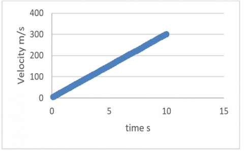
Where the motion diagram is accelerating with a time of 10 seconds simulation in the ANSYS program because the simulation process requires a large amount of time with an increase in the study time as shown in Figure 5.
Figure 5. Motion diagram
The results of the designs of the proposed wheel shapes are calculated numerically and these results are compared with each other to reach the optimal shape of the wheel. The outputs necessary for this job will be decided after creating the design mesh for the suggested wheel profile and applying the necessary forces. The deformation contour, stress contour, and distance contour at (a) shape 1, (b) shape 2, (c) shape 3, and (d) shape 4 are the significant key factors that need to be determined. To determine the best shape for the proposed wheel profile, the results of the various designs are mathematically calculated and compared to one another.
3.1 The results of the numerical work
The numerical side represents the analytical side of the motion vehicles in relation to the frame, where the real dimensions were taken and their speed was applied while preserving the dimensions of the wheel shapes. Because the numerical side does need programming in the computer field, four-wheel shapes were taken and compared with each other to obtain the largest speed that can be reached without derailing.
(a)
(b)
(c)
(d)
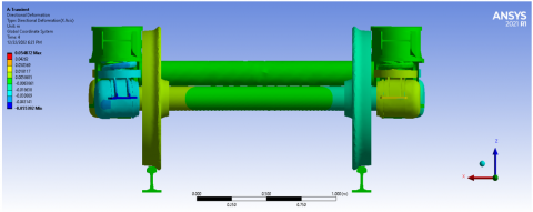
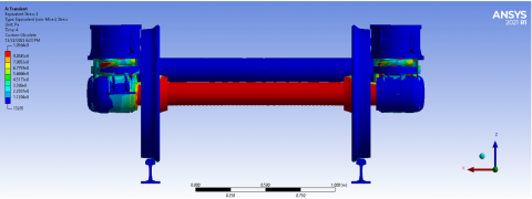
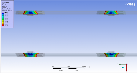
Figure 6. Deformation contour at (a) shape 1, (b) shape 2, (c) shape 3 and (d) shape 4
Figure 6 represents distortions caused by movement in different shapes. It was observed that wheel shape 1, which represents the real condition of the modified wheel in the experimental work, has balance in terms of movement. In addition, it does not deviate from the track, while wheel shape 3, which represents the real state of the wheel manufactured by the company, has much less balance in terms of deformations and derailments. As well as shape 4, which was the worst in terms of Deformation contour. As for wheel shape 2, they represent modification to the wheel shape, but only in case of failure. Where the deformation was significant was in the shape of the wheel.
(a)
(b)
(c)
(d)
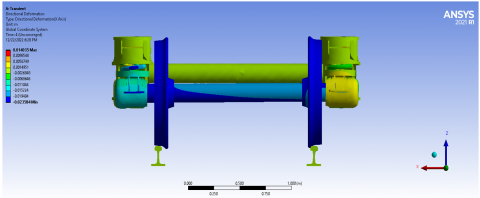
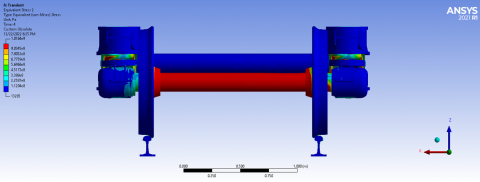
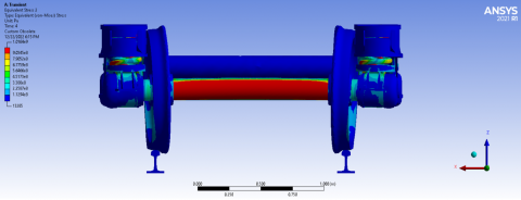
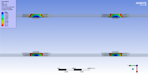
Figure 7. Stress contour at (a) shape 1, (b) shape 2, (c) shape 3 and (d) shape 4
(a)
(b)
(c)
(d)
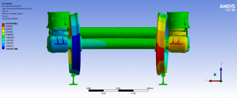
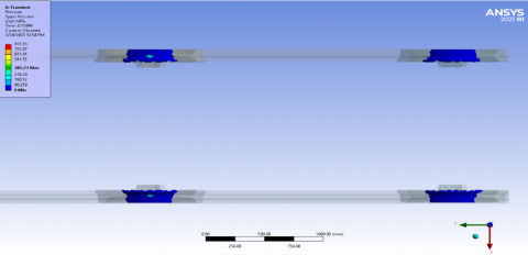
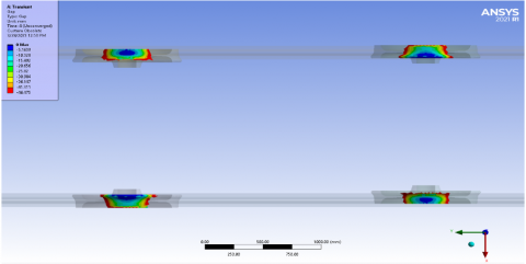
Figure 8. Pressure at (a) shape 1, (b) shape 2, (c) shape 3 and (d) shape 4
(a)
(b)
(c)
(d)
Figure 9. Gap at (a) shape 1, (b) shape 2, (c) shape 3 and (d) shape 4
As for Figure 7, it represents the stresses that occur because of the derailment of the treads. In wheel 1, we see the large distribution of stresses on the bogie, not on the wheels. As for wheel 4, it puts great stress on the wheels because of their torsion inward and the correct exit of the wheel.
Figure 8 shows the points of pressure on the rail by the wheel, where the shape (1) of the new wheel has the highest value of pressure on the rail, which gives sufficient contact space between the wheel and the rail, then follows the shape of the second wheel in terms of contact area, then the shape of The third wheel, which represents the original shape of the railway used in the original train, then the shape (4), which represents the worst of the four shapes, as it showed the ideal condition of pressure on the rail in the new first wheel, which indicates the choice to use the shape (1) that gives stability to the railway wheel. As for the results in Figure 9 represented by the gap, it also showed that the shape (1) is the best in terms of the gap, then the shape (2), then the shape (3), and then the shape (4), which was the worst, as the shape (4) showed a large gap between the wheel and the rail. The main results of the previous shapes were calculated, where it was noted that the maximum equivalent stress is very high, the maximum deformation very large compared to the shape 1.
The most significant findings from this research can be summarized up as follows:
(1) Four-wheel shapes were taken and compared with each other to obtain the largest speed that can be reached with distortions because of movement in different shapes. It was observed that wheel shape 1, which represents the real condition of the modified wheel in the theoretical work, has balance in terms of movement and does not deviate from the track.
(2) In wheel 1, we see the large distribution of stresses on the bogie, not on the wheels. In wheel 4, the stress is due to the wheel's torsion inward and not the correct exit of the wheel. We also see the stresses that occur because of the derailment of the treads.
(3) The speed that can be reached without derailing is what determines the effectiveness of the wheels. The shape 1 of the wheel has covered a long distance reached 272km/h, while in the wheel 2, the speed reached 243km/h. In wheel 3, which is considered the design of the company, it reached 167km/h.
(4) Four-wheel shapes were taken and compared with each other to obtain the largest speed that can be reached, distortions as a result of movement in different shapes. It was observed that the wheel shape 1, which represents the real condition of the modified wheel in the theoretical work, has balance in terms of movement and does not deviate from the track.
(5) In wheel 1, we see the large distribution of stresses on the bogie, not on the wheels. In wheel 4, the stress is due to the wheel's torsion inward and not the correct exit of the wheel. We also see the stresses that occur as a result of the derailment of the treads.
(6) Suspension joins are considered one of the basics for derailing the wheels. It is suggested to take more than one type of suspension join for this work.
(7) Analyzing in simulation programs the weights used for the bogie, as well as taking into account more than one bogie.
[1] Mohan, A. (2003). Nonlinear investigation of the use of controllable primary suspensions to improve hunting in railway vehicles. Doctoral Dissertation, Virginia Tech.
[2] Ali, K.H., Majeed, F.A.A. (2018). Improve roll dynamic response of road vehicle to step steer input using semi-active PID suspension controller. International Journal of Computer Applications, 25(2): 8-14.
[3] Liu, B., Mei, T.X., Bruni, S. (2016). Design and optimisation of wheel-rail profiles for adhesion improvement. Vehicle System Dynamics, 54(3): 429-444. https://doi.org/10.1080/00423114.2015.1137958
[4] Illingworth, R. (1986). The role of theoretical prediction methods in the design of railway vehicle suspensions and track geometry. Proceedings of the Institution of Mechanical Engineers, Part D: Transport Engineering, 200(1): 27-36. https://doi.org/10.1243/PIME_PROC_1986_200_160_02
[5] Jaschinski, A., Chollet, H., Iwnicki, S., Wickens, A., Würzen, J. (1999). The application of roller rigs to railway vehicle dynamics. Vehicle System Dynamics, 31(5-6): 345-392. https://doi.org/10.1076/vesd.31.5.345.8360
[6] Bruni, S., Cheli, F., Resta, F. (2001). A model of an actively controlled roller rig for tests on full-size railway wheelsets. Proceedings of the Institution of Mechanical Engineers, Part F: Journal of Rail and Rapid Transit, 215(4): 277-288. https://doi.org/10.1243/0954409011531576
[7] Magel, E.E., Kalousek, J. (2002). The application of contact mechanics to rail profile design and rail grinding. Wear, 253(1-2): 308-316. https://doi.org/10.1016/S0043-1648(02)00123-0
[8] Shevtsov, I., Markine, V., Esveld, C. (2002). Optimization of railway wheel profile using MARS method. In 43rd AIAA/ASME/ASCE/AHS/ASC Structures, Structural Dynamics, and Materials Conference, Denver, Colorado, p. 1320. https://doi.org/10.2514/6.2002-1320
[9] Simson, S.A., Cole, C. (2007). Idealized steering for hauling locomotives. Proceedings of the Institution of Mechanical Engineers, Part F: Journal of Rail and Rapid Transit, 221(2): 227-236. https://doi.org/10.1243/0954409JRRT102
[10] Allotta, B., Pugi, L., Malvezzi, M., Bartolini, F., Cangioli, F. (2010). A scaled roller test rig for high-speed vehicles. Vehicle System Dynamics, 48(S1): 3-18. https://doi.org/10.1080/00423111003663576
[11] Park, J.H., Koh, H.I., Kim, N.P. (2011). Parametric study of lateral stability for a railway vehicle. Journal of Mechanical Science and Technology, 25: 1657-1666. https://doi.org/10.1007/s12206-011-0421-0
[12] Choi, Y.S., Shin, B.S. (2015). Critical speed of high-speed trains considering wheel-rail contact. Journal of Mechanical Science and Technology, 29: 4593-4600. https://doi.org/10.1007/s12206-015-1004-2
[13] Mao, X., Shen, G. (2018). A design method for rail profiles based on the geometric characteristics of wheel-rail contact. Proceedings of the Institution of Mechanical Engineers, Part F: Journal of Rail and Rapid Transit, 232(5): 1255-1265. https://doi.org/10.1177/0954409717720346
[14] Sun, J., Chi, M., Cai, W., Jin, X. (2019). Numerical investigation into the critical speed and frequency of the hunting motion in railway vehicle system. Mathematical Problems in Engineering, 2019. https://doi.org/10.1155/2019/7163732
[15] Mikhailov, E., Semenov, S., Shvornikova, H., Gerlici, J., Kovtanets, M., Dižo, J., Blatnický, M., Harušinec, J. (2021). A study of improving running safety of a railway wagon with an independently rotating wheel’s flange. Symmetry, 13(10): 1955. https://doi.org/10.3390/sym13101955
[16] Hassan, K., Dammed, A.A. (2017). Control and simulation of semi-active suspension system using PID controller for automobiles under LABVIEW simulink. International Journal of Current Engineering and Technology, 7(5): 1824-1830.