Zainab Faisal Mutashar Falih | Ammar Jasim Dakhi*![]() | Samoel Mahdi Saleh
| Samoel Mahdi Saleh![]()
© 2023 IIETA. This article is published by IIETA and is licensed under the CC BY 4.0 license (http://creativecommons.org/licenses/by/4.0/).
OPEN ACCESS
Masonry construction, an archaic and versatile building technique, entails the assembly of varied or homogeneous components (including brick, concrete block, stone, etc.) bound by cohesive agents such as mortar. The purpose of this study was to authenticate the validity of an ABAQUS-based solution corresponding to the experimental model of masonry shear walls tested by Raijmakers and Vermeltfoort under in-plane loading, thereby substantiating a developed Finite Element (FE) model. Utilizing a general non-linear static procedure, the ABAQUS finite element software was employed for scrutinizing a continuous (990×1000) mm brick wall, absent of any openings. Analysis of the unreinforced masonry (URM) wall, facilitated by the ABAQUS software, yielded results that closely mirrored those of the experimental model. This comparison serves to underscore the implications of the current modeling approach and the proposed wall properties on its response, thereby fostering an enhanced comprehension of the global in-plane behavior of unreinforced brick masonry walls.
URM walls, in-plane loading, ABAQUS, continuum, general non-linear static procedure
Bricks, a durable and versatile building material, first appeared in Iraq between 3500 and 5000 B.C. [1-4]. The technology and use of bricks evolved and expanded during the Akkadian and Babylonian civilizations, as seen in the ziggurats of the Ur dynasty, temples, and Babylonian era ziggurats [1]. Al-Madaen, a city from the pre-Islamic period, proudly showcases several brick structures. This trend continued into the Islamic eras, with cities like Baghdad and Samarra witnessing the construction of numerous castles, palaces, and emirate residences, including noteworthy structures such as Al-Mustansiriya School and Al-Asheq Palace [1].
Today, brick continues to be a favored material in most residential and commercial constructions in Iraq. This popularity can be attributed to several factors, including the ready availability of raw materials and the simplicity of the brick manufacturing process, which does not require high levels of technical skills or competencies [1].
Various researchers have conducted numerous studies on brick walls over the years. For instance, Meillyta [5] numerically simulated the behavior of Unreinforced Masonry (URM) with openings. The study examined the behavior of URM walls with three types of openings under two values of horizontal pre-compressive load. A load-drift relationship for the wall was developed using the Finite Element (FE) method with ABAQUS and an explicit solver. The results indicated that the horizontal load capacity of the walls was influenced by the opening area and pre-compressive load.
Furthermore, Sharma and Khare [6] evaluated the seismic performance of URM walls under seismic load. They executed a non-linear static analysis using SAP2000 and a homogenous modeling approach. The research results indicated that a 16*16 finite element mesh size was optimal for the task at hand, and intermediate mortar outperformed both stronger and weaker mortar types. In 2017, Abbas and Saeed [7] utilized the ABAQUS software to simulate masonry wall behavior using three modeling approaches: micro, simplified micro, and macro strategies. The macro modeling technique was chosen to represent masonry rooms under seismic load due to its efficiency in reducing time and effort. The Concrete Damage Plasticity (CDP) method was implemented to establish non-linear properties of concrete and masonry. A significant correlation was observed between the results of the numerical investigation and the values derived from the experimental trial for the masonry wall.
In the same year, Abdulla et al. [8] proposed a method combining the Extended Finite Element Method (XFEM) with constitutive models based on plasticity. This combination was applied to a simplified micro model approach to simulate three-dimensional non-linear behavior of a masonry wall under in-plane, out-of-plane, and cyclic load using ABAQUS 6.13 software. The models incorporated the Drucker Prager (DP) plasticity model and surface-based cohesive behavior. The results demonstrated substantial accuracy between the masonry wall models and the published experimental studies.
Furthermore, in 2020, Choudhury et al. [9] evaluated three models of masonry shear walls with various opening arrangements, in addition to a single Unreinforced Masonry (URM) room building comprised of these walls. The analysis made use of Concrete Damage Plasticity (CDP) in ABAQUS. To validate the sophisticated numerical modeling, experimental data were juxtaposed with numerical outcomes using two distinct Finite Element (FE) models. The results indicated that the second method was an effective instrument for analyzing Unreinforced Masonry (URM) buildings and formulating strategies to reduce their seismic vulnerability.
In 2020, Sharma et al. [10] published the results of incremental dynamic tests on four full-scale URM masonry walls constructed with intentionally weaker mortar. These walls were subjected to bending excitation in two ways for the out-of-plane (OOP) direction and experienced simultaneous vertical and horizontal stimulation. Their research provided simple, yet mechanically robust strategies for estimating peak force resistance and the displacement at which such resistance is reached.
In the same year, Kamrava et al. [11] carried out a Finite Element (FE) analysis to examine the in-plane behavior of perforated URM walls. Brick walls were simulated in ABAQUS using 3D micro-modeling. The strong correlation between experimental and numerical analysis results suggested that the model is reliable for simulating URM walls.
In the present study, a general non-linear static procedure is employed to investigate the behavior of an Unreinforced Brick Masonry (URM) shear wall without openings under in-plane loading. This investigation utilizes ABAQUS, a commercially available FE software.
There are several methods and scales for representing the mechanical behavior of masonry have been proposed due to the complexity of this kind of structure. Each modeling strategy has its own set he assumptions that, in general, can be applied to a specific kind of problem. The current modeling approaches for unreinforced masonry structures are divided into the following categories [12]:
a. Models based on blocks:
It represents the masonry behavior at the scale of the material's primary heterogeneity and is classified by blocks joined together by mortar joints, which consist of the failure response and the material's mechanical. Actually, the texture of the masonry can be taken into account, which has a major influence on the failure pattern and material's anisotropy [12]. Block-based models are divided into several kinds depending on how the action between blocks is represented: Extended finite element approaches [8], Contact-based approaches [13-15], Block-based limit analysis approaches [16], and Textured continuum-based approaches [17] and Interface element-based approaches [18]. Figure 1(a) shows an example of block-based models.
b. Macroelement models:
This method is employed to measure the global non-linear earthquake response of existing unreinforced structures (URM) simply. There is a general assumption that macro element models prevent the excitation of local failure modes, primarily connected with masonry wall behavior under out-of-plane [19]. It is favoured in professional practice because only a few mechanical parameters are needed, and structural analysis can be carried out quickly and at a low-cost thanks to a low computational burden. The structure was idealized as an assemblage of piers (vertical) and spandrel (horizontal) elements. Typically, the spandrels and piers are schematically represented as two-node elements and are linked to each other via infinitely rigid beams or rigid offsets to illustrate the coupling among elements that are deformable [19]. This method includes two approaches: The equivalent beam-based approach [19], and the Spring-based approach [20]. Figure 1(b) shows an example of macro element models.
c. Models based on geometry:
In this method, the structure was modeled as a rigid body. The geometry of the structure is essentially the major input, other than the loading condition. The model of Heyman's rigid no-tension and limit analysis was usually utilized [12, 21], and divided into two approaches: Static Theorem‑Based Approaches (which are suited to the study of equilibrium states in masonry vaulted structures) [22, 23], and Kinematic Theorem‑Based Approaches (which employed in recent years for quick and effective evaluation of existing masonry structures, but they are unable to offer information on masonry structures’ displacement capacity [24]. Figure 1(c) shows an example of geometry-based models.
d. Continuum models:
For analyses that are large and practice-oriented, where a balance of efficiency and accuracy was required, this method was a viable approach. Because the material is treated as an orthotropic homogenous continuum, it offers significant computational benefits in terms of decreased time and memory needs, in addition to user-friendly mesh generation [25]. In terms of global structure behavior, the units and mortar interaction are usually negligible. Material is classified as an anisotropic composite, and average masonry strains and stresses relation is established. The orthotropic material must next be reproduced using a comprehensive macro model with different strengths of the tensile and compressive along the axes of material [26]. The application of suitable and useful homogenous constitutive laws for masonry can be accomplished in one of two ways:
• Direct approaches: To give the total masonry’s mechanical response approximately, these processes use calibrated mechanical properties like elastic parameters or any other properties, from experimental trials or any other data like domains of analytical strength determined experimentally [26-28].
• Homogenization procedures: Using a homogenized procedure, a material-scale model is connected to a structural-scale model (which represents the major heterogeneities) in order to obtain the constitutive law of the material [29-31].
Figure 1(d) shows an example of a continuum model.
Figure 1. Examples of modeling strategies
Raijmakers and Vermeltfoort [32] evaluated brick shear walls without a central opening, specifically J4D, J5D, and J6D walls, in the Netherlands in 1992 as part of the CUR project, CUR (1994) [33]. The experimentally results of walls J4D and J5D are adopted in this work for validation of the numerical model as follows:
Figure 2. Installing the masonry shear wall [8] based on the study [32]
In this part, the specifics of the URM walls' Finite Element modeling in the ABAQUS program are discussed.
The simulation and analysis of the unreinforced brick wall in this paper were conducted using a continuum strategy. This was accomplished by simulating the wall's geometry using the experimental specimen's global dimensions. Regarding the Abaqus model, only one part of the geometry (brick masonry wall) is defined in the part module by using SI (mm) dimensions.
The main mechanical characteristics of a brick wall are its elastic modulus (Em), Poisson’s ratio ($v$), density, compressive and tensile strengths, and stress-strain curves. These characteristics are necessary for modeling. The wall parameters from experimental tests have been adjusted according to studies [34, 35] to reproduce the elastic and plastic properties of the continuum brick wall. For the elastic properties, the modulus of elasticity (Em) can be derived from Eq. (1) [34]. Table 1 shows the elastic properties of the wall.
$E_m=550 f_m^{\prime} M P a$ (1)
where,
$f_m^{\prime}$: Ultimate brick masonry prism compressive strength in MPa.
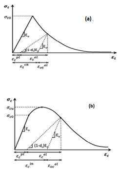
Following a basic classification of all material implementations in Abaqus, Concrete Damaged Plasticity (CDP) the most appropriate model for the material was chosen to describe the nonlinear compression and tension behaviour in the plastic range [36]. CDP models were proposed by Lubliner et al. and Lee and Fenves are the theory references for this implementation [37]. This model gives a general ability for concrete analysis and is appropriate for brick masonry or any other quasi-brittle materials in all types of constructions [37]. The uniaxial compressive and tension responses are shown in Figure 3. Other parameters are required for CDP for quasi-brittle materials in ABAQUS. These parameters are tabulated in the Table 2.
Figure 3. Typical uniaxial loading response in the (a) tension; and (b) compression [37, 38]
Masonry's compressive strength ($f_m^{\prime}$) is determined by bricks and mortar strengths. The nonlinear behavior between the two strengths was discovered empirically from Eq. (2) [34], with the effects of the individual strength on the total masonry strength.
$f_m^{\prime}=0.63 f_b^{0.49} f_j^{0.32}$ (2)
The parabolic brick masonry stress-strain curve, adopted in this study, was shown in Figure 4 [34] and can be described in expressions of stress and strain ratios in a non-dimensional form as:
$\frac{f_m}{f_m^{\prime}}=2 \frac{\varepsilon_m}{\varepsilon_m^{\prime}}-\left(\frac{\varepsilon_m}{\varepsilon_m^{\prime}}\right)^2$ (3)
where,
$\varepsilon_m^{\prime}=C_j \frac{f_m^{\prime}}{E_m^{0.7}}$
$f_m^{\prime}$: Ultimate masonry prism compressive strength in MPa.
fb: Ultimate brick unit compressive strength in MPa.
fj: Ultimate mortar compressive strength in MPa.
fm: Compressive stress in masonry (MPa).
εm: Compressive strain in masonry.
Cj: Factor based on the strength of the mortar used in prism =$\frac{0.27}{f_j^{0.25}}$.
Figure 4. Compressive stress-strain curve [34]
Eq. (4) defines the elastic strain in compression [39]. Then the inelastic deformation, plastic strain, and damage parameters (dc) can be found in Eqs. (5)-(7), respectively [39].
$\varepsilon_{c o}^{e l}=\frac{\sigma_c}{E_0}$ (4)
$\varepsilon_c^{i n}=\varepsilon_c-\varepsilon_{c o}^{e l}$ (5)
$\varepsilon_c^{p l}=\varepsilon_c^{i n}-\frac{d_c}{\left(1-d_c\right)} \cdot \frac{\sigma_c}{E_o}$ (6)
$d_c=1-\frac{\sigma_c}{\sigma_c^{\prime}}$ (7)
where,
$\sigma_c^{\prime}$: The brick masonry has compressive strength.
The unreinforced brick masonry tensile strength is estimated from Eq. (8), which suggests that the masonry tensile strength is 5.5% of its compressive strength [35]. Figure 5 showed an empirically estimated tensile curve [35].
Figure 5. Empirically estimated tensile curve [35]
$f_t=5.5 \% \cdot f_m^{\prime}$ (8)
where, ft: Brick masonry tensile strength in (MPa).
The mathematical expression for the tensile behavior of brick masonry material is illustrated by Eqs. (9)-(10).
$\sigma_t^1=E_c \varepsilon_t$ (9)
$\sigma_t^2=f_{c r}\left(\frac{\varepsilon_{c r}}{\varepsilon_t}\right)^c$ (10)
where,
fcr: The cracking strength (MPa).
εcr: The strain under fracture strength.
c: the stiffening parameter that determines the model curve՚s sharpness post-cracking=0.2 [35].
Similar to compression strain, elastic strains in tension can be determined using Eq. (11), while inelastic deformation, plastic strain, and damage parameters (dt) can be found in Eqs. (12)-(14), respectively.
$\varepsilon_{t o}^{e l}=\frac{\sigma_t}{E_0}$ (11)
$\varepsilon_t^{i n}=\varepsilon_t-\varepsilon_{t o}^{e l}$ (12)
$\varepsilon_t^{p l}=\varepsilon_t^{i n}-\frac{d_t}{\left(1-d_t\right)} \cdot \frac{\sigma_t}{E_o}$ (13)
$d_t=1-\frac{\sigma_t}{\sigma_t^{\prime}}$ (14)
where,
$\sigma_t^{\prime}$: The brick masonry tensile strength.
All the details for the compressive and tensile values and the damage parameters are tabulated in Tables 3 and 4.
Table 1. Bricks wall’s elastic properties in Abaqus
|
Brick Wall Elasticity |
|
|
Density (tonne/mm3) |
1.8E-9 |
|
Young's Modulus (MPa) |
5070.541896 |
|
Poisson's Ratio (υb) [32] |
0.18 |
Table 2. Plastic properties for the brick wall in Abaqus
|
Plasticity Parameters |
||||
|
Dilation Angle [37] |
Eccentricity |
fbo⁄fco [39] |
K [39] |
Viscosity Parameter |
|
10 |
0.1 |
1.3 |
0.51 |
0.02 |
Table 3. Compressive behaviour properties for the bricks wall in Abaqus
|
Brick Wall Compressive Behavior |
Brick Wall Compression Damage |
||
|
Yield stress (MPa) |
Inelastic strain |
Damage parameter |
Inelastic strain |
|
3.042325137 |
0 |
0 |
0 |
|
4.5 |
0.000151173 |
0 |
0.000151173 |
|
6.914375312 |
0.000515895 |
0 |
0.000515895 |
|
7.6 |
0.00070856 |
0 |
0.00070856 |
|
9.219167083 |
0.002193179 |
0 |
0.002193179 |
|
8.7 |
0.003395652 |
0.056313882 |
0.003395652 |
|
8.297250375 |
0.003853536 |
0.1 |
0.003853536 |
|
4.609583541 |
0.006547853 |
0.5 |
0.006547853 |
|
1.843833417 |
0.008567385 |
0.8 |
0.008567385 |
Table 4. Tensile behavior properties for the brick wall in Abaqus
|
Brick Wall Tensile Behavior |
Brick Wall Tension Damage |
||
|
Yield stress (MPa) |
Cracking strain |
Damage parameter |
Cracking strain |
|
0.50705419 |
0 |
0 |
0 |
|
0.491033112 |
2.62829E-05 |
0.031596382 |
2.62829E-05 |
|
0.463578229 |
8.32002E-05 |
0.085742238 |
8.32002E-05 |
|
0.443344198 |
0.000138298 |
0.125647304 |
0.000138298 |
|
0.427469152 |
0.000192298 |
0.156955685 |
0.000192298 |
|
0.414491302 |
0.000245568 |
0.182550286 |
0.000245568 |
|
0.405825293 |
0.000286751 |
0.19964118 |
0.000286751 |
In the assembly module, two reference points were put at the centres of the top and bottom wall faces. These points were kinematic coupling constraints to the faces in the interaction module.
The numerical investigation can be achieved by executing two major steps. In the first one, vertical compression stress is put. During the second step, an incremental application of the horizontal in-plane monotonic load was performed under displacement control while the vertical and out-of-plane horizontal displacement were tied at the top of the wall. These two steps will maintain the experiment boundary condition. Figure 6 shows the compression load and boundary conditions on the wall. The period of this analysis was one second with details shown in Table 5.
Figure 6. Compression load and boundary conditions for the wall
Table 5. Details of step module
|
Time Period |
One Second |
||
|
Maximum number of increments |
10000 |
||
|
Increment size |
Initial |
Minimum |
Maximum |
|
0.1 |
1E-15 |
0.1 |
|
In this work, a general non-linear static method has been used for following the Newton-Raphson algorithm solution, which repeated solves for equilibrium in increments, and there is no imposed time scale in static problems, so time step choice is only based on accuracy in modelling nonlinear effects as discussed in Abaqus Theory Guide.
30954 elements resulted after meshing the wall in global seeds with a 3D stress element (C3D8R) with an approximate size equal to15mm as shown in Figure 7. The reason for using (C3D8R) is because a linear brick element of the first order is commonly used for large models like brick and mortar with a simpler and faster calculation time. However, the whole purpose of developing a reduced integration element was to increase computational efficiency without losing accuracy.
Figure 7. Mesh of the numerical model
Subsequently modeling and completing the analysis process with Abaqus/Standard, Figure 8 displays the load-displacement curve obtained from the previous experimental and numerical results as well as the current Abaqus model.
Figure 8. Comparison of the numerical and experimental results
In the adopted Abaqus model, the maximum load is equal to 47.0855 kN which is near enough to the maximum load from the experimental investigation for J4D and J5D walls: 51.438 kN and 53.043 kN, respectively. The inaccurate adoption of material properties could be one reason for this difference. The numerical model employed some material parameters, as previously discussed, which were derived from literature parameters relevant to the materials. The experiment does not contain all the parameters required to derive the properties of the continuum brick wall that was used in this work with the properties of concrete damage plasticity. Using concrete-damaged plasticity as an inelastic model to easily visualize the damage in compression and tension situations. In determining the parameters of plasticity, trail tests are performed using the default tension and compression values determined from mathematical expressions. Despite this, the final results of the numerical analysis and experimental results are reasonably close.
The current study aims to evaluate the performance of unreinforced masonry shear walls without openings under in-plane loading. This evaluation is achieved by comparing an earlier experimental study with a contemporary numerical model. The continuum representation technique has been utilized to predict the wall's global behavior using the non-linear general static method in ABAQUS/Standard. Upon analysis using the ABAQUS software, it was found that the results closely align with the experimental model. This suggests that this numerical representation can be effectively applied to more complex analysis conditions in future investigations.
This work is part of Mrs Zainab Faisal Falih's master thesis under the supervision of Dr Ammar Jasim Dakhil and Dr Samoel Mahdi Saleh.
[1] Aljanabi, A.J.T. (2015). Brick Industry in Iraq for the period (2000-2012) (An analytical study), Arabic research. AL-ADAB Journal, 110.
[2] Almudhaffar, M., Monem, A.A., Naseer, A.H. (2014). Standardizing the annual electric energy consumption for a residential building in Basrah City. Basrah Journal for Engineering Science, 14(2): 162-175.
[3] Saadoon, A.S., Abbas, A.M., Almayah, A.A. (2019). Revision study of green concrete. Basrah Journal for Engineering Sciences, 19: 33-38. https://doi.org/10.33971/bjes.19.2.5
[4] Dakhil, A., Naji, Z.M., Al Jasim, S. (2022). Improving clay brick column’s compression capacity using CFRP sheets and reinforced concrete jacketing. Iraqi Journal of Civil Engineering, 15(2): 29-40. https://doi.org/10.37650/ijce.2021.172871
[5] Meillyta, M. (2012). Finite element modelling of Unreinforced Masonry (URM) wall with openings: Studies in Australia. In 2nd Syiah Kuala University Annual International Conference 2012. Syiah Kuala University.
[6] Sharma, A., Khare, R. (2016). Pushover analysis for seismic evaluation of masonry wall. International Journal of Structural and Civil Engineering Research, 5(3): 235-240. https://doi.org/10.18178/ijscer.5.3.235-240
[7] Abbas, A.L., Saeed, M.H. (2017). Representation of the masonry walls techniques by using FEM. Australian Journal of Basic and Applied Sciences, 11(13): 39-48.
[8] Abdulla, K.F., Cunningham, L.S., Gillie, M. (2017). Simulating masonry wall behaviour using a simplified micro-model approach. Engineering Structures, 151: 349-365. https://doi.org/10.1016/j.engstruct.2017.08.021
[9] Choudhury, T., Milani, G., Kaushik, H.B. (2020). Experimental and numerical analyses of unreinforced masonry wall components and building. Construction and Building Materials, 257: 119599. https://doi.org/10.1016/j.conbuildmat.2020.119599
[10] Sharma, S., Tomassetti, U., Grottoli, L., Graziotti, F. (2020). Two-way bending experimental response of URM walls subjected to combined horizontal and vertical seismic excitation. Engineering Structures, 219: 110537. https://doi.org/10.1016/j.engstruct.2020.110537
[11] Kamrava, A.R., Najafgholipour, M.A., Fathi, F. (2021). A numerical investigation on the in-plane behavior of perforated unreinforced masonry walls. Iranian Journal of Science and Technology, Transactions of Civil Engineering, 45: 545-560. https://doi.org/10.1007/s40996-020-00518-2
[12] D’Altri, A. M., Sarhosis, V., Milani, G., Rots, J., Cattari, S., Lagomarsino, S., Sacco, E., Tralli, A., Castellazzi, G., de Miranda, S. (2020). Modeling strategies for the computational analysis of unreinforced masonry structures: Review and classification. Archives of Computational Methods in Engineering, 27: 1153-1185. https://doi.org/10.1007/s11831-019-09351-x
[13] D'Altri, A.M., Messali, F., Rots, J., Castellazzi, G., de Miranda, S. (2019). A damaging block-based model for the analysis of the cyclic behaviour of full-scale masonry structures. Engineering Fracture Mechanics, 209: 423-448. https://doi.org/10.1016/j.engfracmech.2018.11.046
[14] Sarhosis, V., Lemos, J.V. (2018). A detailed micro-modelling approach for the structural analysis of masonry assemblages. Computers & Structures, 206: 66-81. https://doi.org/10.1016/j.compstruc.2018.06.003
[15] Smoljanović, H., Nikolić, Ž., Živaljić, N. (2015). A combined finite–discrete numerical model for analysis of masonry structures. Engineering Fracture Mechanics, 136: 1-14. https://doi.org/10.1016/j.engfracmech.2015.02.006
[16] Orduña, A., Lourenço, P.B. (2005). Three-dimensional limit analysis of rigid blocks assemblages. Part II: Load-path following solution procedure and validation. International Journal of Solids and Structures, 42(18-19): 5161-5180. https://doi.org/10.1016/j.ijsolstr.2005.02.011
[17] Petracca, M., Pelà, L., Rossi, R., Zaghi, S., Camata, G., Spacone, E. (2017). Micro-scale continuous and discrete numerical models for nonlinear analysis of masonry shear walls. Construction and Building Materials, 149: 296-314. https://doi.org/10.1016/j.conbuildmat.2017.05.130
[18] Lourenço, P.B., Rots, J.G. (1997). Multisurface interface model for analysis of masonry structures. Journal of Engineering Mechanics, 123(7): 660-668. https://doi.org/10.1061/(ASCE)0733-9399(1997)123:7(660)
[19] Quagliarini, E., Maracchini, G., Clementi, F. (2017). Uses and limits of the Equivalent Frame Model on existing unreinforced masonry buildings for assessing their seismic risk: A review. Journal of Building Engineering, 10: 166-182. https://doi.org/10.1016/j.jobe.2017.03.004
[20] Xu, H., Gentilini, C., Yu, Z., Wu, H., Zhao, S. (2018). A unified model for the seismic analysis of brick masonry structures. Construction and Building Materials, 184: 733-751. https://doi.org/10.1016/j.conbuildmat.2018.06.208
[21] Heyman, J. (1966). The stone skeleton. International Journal of Solids and Structures, 2(2): 249-279. https://doi.org/10.1016/0020-7683(66)90018-7
[22] Huerta Fernández, S. (2001). Mechanics of masonry vaults: The equilibrium approach. En: Historical Constructions. Possibilities of numerical and experimental techniques. Universidade do Minho, Guimaraes, Portugal, pp. 47-69.
[23] D'Altri, A.M., Castellazzi, G., de Miranda, S., Tralli, A. (2017). Seismic-induced damage in historical masonry vaults: A case-study in the 2012 Emilia earthquake-stricken area. Journal of Building Engineering, 13: 224-243. https://doi.org/10.1016/j.jobe.2017.08.005
[24] Chiozzi, A., Milani, G., Grillanda, N., Tralli, A. (2018). A fast and general upper-bound limit analysis approach for out-of-plane loaded masonry walls. Meccanica, 53: 1875-1898. https://doi.org/10.1007/s11012-017-0637-x
[25] Pelà, L., Cervera, M., Roca, P. (2013). An orthotropic damage model for the analysis of masonry structures. Construction and Building Materials, 41: 957-967. https://doi.org/10.1016/j.conbuildmat.2012.07.014
[26] Lourenço, P.B., Rots, J.G., Blaauwendraad, J. (1998). Continuum model for masonry: Parameter estimation and validation. Journal of Structural Engineering, 124(6): 642-652. https://doi.org/10.1061/(ASCE)0733-9445(1998)124:6(642)
[27] Lourénço, P.B., De Borst, R., Rots, J.G. (1997). A plane stress softening plasticity model for orthotropic materials. International Journal for Numerical Methods in Engineering, 40(21): 4033-4057. https://doi.org/10.1002/(SICI)1097-0207(19971115)40:21%3C4033::AID-NME248%3E3.0.CO;2-0
[28] Lopez, J., Oller, S., Oñate, E., Lubliner, J. (1999). A homogeneous constitutive model for masonry. International Journal for Numerical Methods in Engineering, 46(10): 1651-1671. https://doi.org/10.1002/(SICI)1097-0207(19991210)46:10%3C1651::AID-NME718%3E3.0.CO;2-2
[29] Sacco, E., Addessi, D., Sab, K. (2018). New trends in mechanics of masonry. Meccanica, 53: 1565-1569. https://doi.org/10.1007/s11012-018-0839-x
[30] Zucchini, A., Lourenço, P.B. (2009). A micro-mechanical homogenisation model for masonry: Application to shear walls. International Journal of Solids and Structures, 46(3-4): 871-886. https://doi.org/10.1016/j.ijsolstr.2008.09.034
[31] Zucchini, A., Lourenço, P.B. (2004). A coupled homogenisation–damage model for masonry cracking. Computers & Structures, 82(11-12): 917-929. https://doi.org/10.1016/j.compstruc.2004.02.020
[32] Raijmakers, T., Vermeltfoort, A.T. (1992). Deformation controlled tests in masonry shear walls. Delft: Report B-92-1156, TNO-Bouw.
[33] Lourenço, P.J.B.B. (1997). Computational strategies for masonry structures.
[34] Kaushik, H.B., Rai, D.C., Jain, S.K. (2007). Stress-strain characteristics of clay brick masonry under uniaxial compression. Journal of materials in Civil Engineering, 19(9): 728-739. https://doi.org/10.1061/(ASCE)0899-1561(2007)19:9(728)
[35] Adil, X.R., Fahad, M., Adil, M. (2020). Macro-scale numerical modeling of unreinforced brick masonry squat pier under in-plane shear. Journal of Mechanics of Continua and Mathematical Sciences, 15(11): 72-84. https://doi.org/10.26782/jmcms.2020.11.00007
[36] Rafiq, A., Fahad, M. (2016). Computational modelling of unconfined/unreinforced masonry wall using Abaqus. Doctoral dissertation, MSc thesis, University of Engineering and Technology, Peshawar, Pakistan.
[37] Abaqus Theory Guide 6.14. http://130.149.89.49:2080/v6.14/books/stm/default.htm.
[38] Naciri, K., Aalil, I., Chaaba, A., Al-Mukhtar, M. (2021). Detailed micromodeling and multiscale modeling of masonry under confined shear and compressive loading. Practice Periodical on Structural Design and Construction, 26(1): 04020056. https://doi.org/10.1061/(ASCE)SC.1943-5576.0000538
[39] ABAQUS documentation. http://130.149.89.49:2080/v6.14./.