Abdulrahman Kh. Alhafid*![]() | Yessar Ezzaldeen Mohammed Ali
| Yessar Ezzaldeen Mohammed Ali![]() | Sedki Younis
| Sedki Younis![]()
© 2023 IIETA. This article is published by IIETA and is licensed under the CC BY 4.0 license (http://creativecommons.org/licenses/by/4.0/).
OPEN ACCESS
Reconfigurable intelligent surfaces (RIS) are forecasted to assume a pivotal role in future wireless communication systems, largely attributed to their capacity to dynamically alter the propagation environment. This study primarily concentrates on the utilization of large RIS, leading to near-field propagation channels, especially in high-frequency communication systems. This is aimed at resolving the complex issue of single anchor-based localization, particularly under conditions where the line-of-sight (LoS) path is prone to severe blockage and fading. In this context, a millimeter-wave localization problem, based on time difference of arrival (TDoA), utilizing orthogonal frequency division multiplexing (OFDM) downlink signaling, has been modeled and simulated. The time of arrivals (ToA) measurements, enriched from each RIS tile, are applied to determine user positions. It is recognized that some ToA readings may possess low signal to noise ratio (SNR), making them unsuitable for inclusion in the estimation. Subsequently, various scenarios for RIS tile selection were examined in this research, with the aim of enhancing localization accuracy. Numerical results substantiate the efficacy of the TDoA-RIS algorithm in improving localization accuracy. This is achieved through different strategies to select the most reliable 50% of ToA measurements for the formulation of the estimation procedure.
wireless device localization, reconfigurable intelligent surface (RIS), RIS phase profile, time difference of arrival, orthogonal frequency division multiplexing, Near-Field propagation, multipath channels, time of arrival estimation, positioning system
The rapid evolution of wireless communication systems necessitates high-speed operations along with the precise location estimation of user equipment (UE) within the coverage area. Notably, fifth-generation (5G) mobile communication systems have localized this aspect as an integral factor for not only enabling new location-aware services but also facilitating communication activities [1]. Consequently, research attention is being redirected towards the next-generation of wireless networks, i.e., 6G, projected to impose strict requirements for localization accuracy, latency, and reliability [2].
The pursuit of high speed and precise localization warrants operations at high frequency (e.g., millimeter-wave and terahertz) bands, with the abundant bandwidth and the implementation of massive multiple-input multiple-output (MIMO) antennas technology [3, 4]. Nevertheless, the potential coverage and reliability problems pose additional challenges, as obstructions may block signals and multipath may not guarantee sufficient coverage in non-line-of-sight (NLoS) channel propagations. The paramount question is how to ensure a high level of reliability in communications and localization without resorting to cell densification, i.e., without deploying a large number of base stations (BSs), which is a costly and complicated issue.
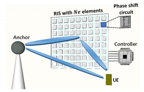
A promising solution is presented in the form of reconfigurable intelligent surfaces (RISs), which enable the formation of a quasi-continuous antenna array [5-8]. Emerging technologies, such as metamaterial-based intelligent surfaces, can be used to create passive RISs or active large intelligent surfaces (LISs), serving as extremely flexible antennas [9, 10]. As depicted in Figure 1, a reconfigurable surface with passive elements can reradiate the impinging signal and control its characteristics via the phase-changing properties of the surface.
Figure 1. Enhanced communication via RIS
Originally developed to improve propagation coverage even in NLoS cases, the RIS can function as a steerable-reflector, anomalous-reflector, lens, mirror transmitter, or receiver [11-13]. It can operate from some GHz to millimeter-wave bands [14]. Furthermore, intelligent surfaces are proposed to augment the estimation accuracy of UEs positions and to address infeasible localization problems, such as single-anchor localization [15]. The near-field region, with its spherical wavefront capable of achieving beam focusing in a certain spatial area, becomes a distinct feature of beyond-5G and future 6G communication systems [16-18].
Previous researches [19, 20] have explored localization and sensing with RIS assistance in the far-field, considering an asynchronous downlink single-input-single-output (SISO) OFDM scenario. The channel parameters, including the angle-of-departure (AoD) and ToA of direct and reflected (from RIS) paths, were estimated to obtain location estimates. However, a search over the channel parameters space was required. In reference [21], the user mobility and spatial-wideband effect on the positioning performance were considered. The low-complexity estimator which is proposed in reference [21] neglected the spatial-wideband effect, and an iterative compensation of the radial velocities was presented. The spatial-wideband effect was found to affect the performance with certain margins; however, the localization accuracy remained unaffected in the presence of user mobility with the adoption of iterative compensator. In reference [22], the TDoA approach was investigated with the assistance of RIS in NLoS conditions in the near-field region. The trade-off between bandwidth, latency, and operating frequency was discussed. In reference [23], the compressed sensing (CS) scheme was adopted to estimate the user equipment with single anchor with the assistance of RIS. It was demonstrated that CS could tolerate the model mismatch and near-field impairments with optimized RIS coefficients compared with non-optimized phases. In reference [24], the effect of phase-dependent amplitude variations of the RIS elements on the localization accuracy in the near-field was considered. The calibration of RIS amplitude model was shown to be effective in recovering the loss in positioning accuracy.
As discussed above, some research has already investigated the use of large RIS operating with high frequency in positioning and localization applications, producing near field regime of propagation with the consideration of LOS/NLoS multipath scenarios. With the enriched localization parameters measurement extracted from each tile of the RIS, this paper focuses on selecting the appropriate tiles that can be incorporated in the estimation such that localization accuracy in NLoS condition can be improved. A simulation framework for TDoA is developed for the position estimation of UE with single antenna aided by the RIS in the near-field condition. The tile selection strategies are evaluated via numerical simulation to investigate the localization accuracy for different tile selection strategies.
The rest of the paper is organized as follows: Section II describes the system model, including the wireless communications components, the geometry design and properties of the used RIS, and the OFDM signaling-based system. Section III explains the localization algorithm used to estimate the UE location. The investigated RIS-tiles selection scenarios used to construct the TDoA and estimate the UE location are discussed in Section IV. Section V presents the simulation model with its parameters description and the numerical results. Finally, conclusions and discussions are drawn in Section VI.
In this section, we describe the RIS-aided localization with TDoA scenario including transmitter (anchor), RIS and a UE. Then express the transmitted signal, derive the received signal expression at the UE, formulate the problem of signal components extraction, ToAs estimation to estimate the UE position. A system model of OFDM SISO downlink wireless system with one transmitter and UE in addition to a RIS is considered as illustrated in Figure 2. The positions of the anchor and the RIS are known and denoted by $\boldsymbol{p}_{A c h}$ and $\boldsymbol{p}_{R I S}$ respectively, while the position of the UE which denoted by $\boldsymbol{p}_{U E}$ is to be estimated using the facilities produced by the RIS.
Figure 2. RIS-assisted localization system model
In the considered system model, the RIS elements are divided to groups or subsets, each groups called tile (as in reference [25]), each tile consists of $N r \times N c$ elements to construct $N e$ uniform planer array (UPA). Hence, the RIS consist of $N_l$ tiles, each tile has known position $\boldsymbol{p}_l, l=$ $1,2,3 \ldots N_l$. The tils are arranged geometrically in one line (instead of rectangular or square RIS) to construct large onedimensional RIS which can call a stripe-like-RIS (as in reference [22]). This arrangement will ensure the working at near-field region as well as reduce the cost and the hardness of installing the RIS on the buildings or walls. That's because, as it's known, to work at near-field propagation region, it requires a sufficiently large RIS, with respect to the wavelength, and/or high frequency. Each element in the RIS is configured independently to modulate the phase of the incident signal before reflecting it. In this paper, all the elements in the tile configured to get the same reflection coefficient that differ from other tiles and vary at each pilot transmission according to predesigned phase shift profile.
Regarding the signal model, a synchronization mismatch between the transmitter and the receiver is assumed. The anchor transmits $N p$ OFDM pilot symbols at time $\mathrm{t}=$ $1,2,3, \ldots T$ with $N s c$ subcarriers at each positioning occasion.
The transmitted signal $x_t$ over $N_p$ transmissions has $\mathbb{E}\left\{\left|s_t\right|^2\right\}=E_s$, and for simplicity we assume that $x_t=\sqrt{E_s}$ any $t$. The carrier frequency of the transmitted signal is $f_c$ and the spacing between the OFDM subcarriers is $\Delta f$, i.e., the frequency of the $n^{\text {th }}$ subcarrier can be described as,
$f_n=f_c+(n-(N s c+1) / 2) \Delta f$ (1)
The transmitted signal reaches the UE from direct path (if not blocked) and also though the RIS which manipulate the signal phase and reflect it back. The reflection coefficient of the $l^{\text {th }}$ tile is expressed as,
$\Upsilon_{t, l}=\Upsilon e^{j \psi_{t, l}}$ (2)
where $\Upsilon$ and $\psi_{t, l}$ are the magnitude and the phase of the reflection coefficient.
The reflection phase $\psi_{t, l}$ can take any value between 0 and $2 \pi$ and it updated at each pilot transmission for each tile. The updated phase shift during each pilot transmission is controlled by a pre-designed phase shift profile. This profile must be able to achieve the signal separation and components extractions. Signal separation and extraction mean the ability of separating the received signal coming directly from the transmitter and extracting the reflected components from each element of the RIS as will be illustrated in next section.
The channel model consists of two parts: direct path channel from the anchor to and the UE and the cascaded channel from the anchor to the UE through the RIS. Each part includes multipath (mp) propagation components. In fact, the case of blocked LoS of the direct path between the anchor and the UE is considered in this study. The scenario of the channel model is illustrated Figure 2.
The direct channel's complex coefficient between the anchor and the UE for subcarrier $n$ is denoted as:
$h_n^d=h_n^{d p}+h_n^{m p}$ (3)
where, $h_n^{d p}$ is direct LoS channel between the UE and the anchor, this component may have zero value when the UE is in NLoS case with respect to the anchor which is considered in this study. $h_n^{m p}$ is the multipath channel components for the scattered signal reached the UE from the anchor.
The LoS direct path component can be expressed by a precise formula as follows:
$h_n^{d p}=h_0 e^{J\left(\omega_n t_0\right)} S\left(\boldsymbol{p}_{A c h}, \boldsymbol{p}_{U E}\right)$ (4)
where, $t_0$ is the clock synchronization offset between the anchor $\left(T_X\right)$ and the UE $h_0$ is complex channel gains for the direct LoS path which is depend on the power of the transmitted subcarrier, on the gains of the transmitter and receiver antennas in addition on the free-space transmission loss between them, $S\left(\boldsymbol{p}_{A c h}, \boldsymbol{p}_{U E}\right)$ is steering vector that depend on the positions of the anchor and the UE, and can be defined as:
$S\left(\boldsymbol{p}_{A c h}, \boldsymbol{p}_{U E}\right)=e^{-J\left(\frac{2 \pi}{\lambda_n}\left\|\boldsymbol{p}_{A c r}-\boldsymbol{p}_{U E}\right\|\right)}$ (5)
Together with the direct channel, tapped delay line multipath channel components are included. An $N_{\text {tap }}$ taps fading model is considered to simulate the multipath channel component for the scattered signal reached the UE from the anchor [26].
On the other hand, the cascaded channel from the anchor to the UE through the RIS consist of the incident or forward channel $h_{n, l}^f$ which is from the anchor to each tile of the RIS, and the exit or backward channel $h_{n, l}^b$ which is from each tile of the RIS to the UE. Each of the two cascaded channel have multipath components. Then the resultant cascaded $h_{n, l}^r$ channel for the $l^{\text {th }}$ tile of the RIS and subcarrier $n$ can be written as:
$h_{n, l}^r=h_{n, l}^f \odot h_{n, l}^b$ (6)
The complex coefficients of the forward and the backward channel are defined respectively in below two equations:
$h_{n, l}^f=h_{n, l}^{f d p}+h_{n, l}^{f m p}$ (7)
$h_{n, l}^b=h_{n, l}^{b d p}+h_{n, l}^{b m p}$ (8)
where, $h_{n, l}^{f d p}$ and $h_{n, l}^{b d p}$ are, respectively, the forward and backward direct LoS path channel coefficient between the UE and the $l^{t h}$ tile and between the UE and the $l^{t h}$ tile of the RIS. Besides, $h_{n, l}^{f m p}$ and $h_{n, l}^{b m p}$ are the forward and backward multipath path channel components for the scattered signal reached each RIS tile from the anchor or reach the UE respectively.
The $l^{\text {th }}$ forward direct component of the $h_{n, l}^f$ part of cascaded channel can be written as:
$h_{n, l}^{f d p}=h_{c f} e^{J\left(\omega_n t_0\right)} S\left(\boldsymbol{p}_{A c r}, \boldsymbol{p}_l\right)$ (9)
$h_{n, l}^{b d p}=h_{c \mathrm{~b}} e^{J\left(\omega_n t_0\right)} S\left(\boldsymbol{p}_l, \boldsymbol{p}_{U E}\right)$ (10)
where, $h_{c \mathrm{f}}$ is complex channel gains for the forward direct $\operatorname{LoS}$ path which is depend on the power of subcarrier, gain of the transmitter antenna and the free-space loss, $h_{c \mathrm{~b}}$ is channel gains for the backward direct LoS path which is depend on the gain of the receiver antenna and the free-space loss, $S\left(\boldsymbol{p}_{A c h}, \boldsymbol{p}_{U E}\right)$ and $S\left(\boldsymbol{p}_l, \boldsymbol{p}_{U E}\right)$ are steering vectors that depend on the positions of the anchor, tiles and the UE, and can be defined as same as in Eq. (5).
Identically to the multipath model of the direct channel between the anchor and the UE, $N_{\text {tap }}$ taps multipath model is considered to simulate the multipath channel component for the scattered signal reached each tile of the RIS from the anchor $h_{n, l}^{f m p}$ and the UE from the tiles $h_{n, l}^{b m p}$.
Subsequently, the observation signal at the UE can be expressed as:
$y_{n, t}=\left[h_n^d 1^T+\sum_{l=1}^{N_l} \Upsilon_{t, l} h_{n, l}^r\right] x_t+n_{n, t}$ (11)
where, $x_t$ is the known transmitted pilot symbol, $Y_{t, l}$ is the RIS phase reflection coefficient and $n_{n, t}$ being an additive noise that generally obeys the distribution of a complex Gaussian random variable with mean and variance of $\mu$ and $\sigma^2$ respectively, and can be expressed as $n_{n, t} \sim C N\left(\mu, \sigma^2\right)$. The UE will collect $N p$ OFDM pilots with $N s c$ subcarriers through observing $y_{n, t}$ with $n=1,2,3, \ldots N s c$ and $\mathrm{t}=$ $1,2,3, \ldots T$, then, these observations exploited to estimate the position of the UE using estimation algorithm that will be specified in the next section.
It's aimed to estimate accurate UE position $\boldsymbol{p}_{U E}$ using the observation signal $y_{n, t}$, so this section will describe the RIS aided localization procedure given in reference [22] where two step localization algorithm is discussed. The process begins with collecting the measurements of $y_{n, t}$, each has $N p$ OFDM received symbols and $N_{s c}$ subcarriers, then exploiting these measurements to estimate the UE position.
The first step involves the extraction of the received signal components given in Eq. (11) thanks to the orthogonality properties of the prepared RIS phase profile. Then the extracted signal components, direct and reflected, are used to estimate the ToA for each one after the up sampling and taking the inverse discrete Fourier transform (IDFT) and search for the peak of the first arrival path. For the reflected path, the ToA for the signal reflected via the RIS is estimated for each tile of the RIS thanks to the near-field regime. Then use some techniques to refine the ToA estimation, after that least square (LS) method is used for TDoA calculations to estimate the UE position, and at last, an outlier filtering is used to ignore the error estimated positions. The steps of the algorithm are illustrated in the generic flowchart diagram for the localization algorithm in Figure 3 (excluding the proposed tiles selections at last step).
Figure 3. RIS aided TDoA based localization algorithm
The extraction mainly depends on the use of balanced sequences to ensure the elimination of any residual noise or clutter. Thus, the RIS, which is composed of large set of reflecting elements, has reflection distinct property changes dynamically according to some unique sequence. This sequence must achieve the orthogonality property due to the sum of phase shift varying at each pilot transmission which can be illustrated in below two equations below:
$\sum_{t=1}^T Y_{t, l}=0 \quad l=1,2, \ldots . N_l$ (12)
and
$\sum_{t=1}^T Y_{t, l} Y_{t, m}^*=0 \quad \forall l \neq m$ (13)
Therefore, the extracted signal model for the direct path between the anchor and the UE, assuming $x=1$, is given as,
$y_n^d=\frac{1}{N_p} \sum_{t=1}^{N_p} y_{n, t}=h_n^{d p}+h_n^{m p}+\bar{n}_n$ (14)
That’s because the orthogonality property in Eq. (12) will make cancellation for all the signals comes from the RIS and remain the signal come directly from the anchor.
At this time the reflected signal components $y_{n, t}^r$ also can be obtained by subtracting the extracted direct signal from the original observation signal to be as,
$y_{n, t}^r=h_{n, l}^f \odot h_{n, l}^b+w_n$ (15)
where, $\bar{n}_n$ and $w_n$ are $\sim C N\left(\mu, \sigma^2\right)$. On the contrary, the property of the RIS profile in Eq. (13) is exploited to extract the signal contribution from each tile, that's done by correlating the components of $y_{n, t}^r$ with the complex conjugate of the known tile phase $Y_{t, l}$.
Then, ToA of the direct path and reflected paths from each tile $\left(\hat{\tau}_j\right)$ are estimated in the time domain by evaluating the peak value of an IDFT of the extracted OFDM frequency domain symbols with oversampling factor of $k$,
$\hat{\tau}_j=\underset{j}{\operatorname{argmax}} \operatorname{IDFT}\left(y_k\right) \quad \ldots \quad i \in[0, M \times N s c-1]$ (16)
where, $y_k$ is the oversampled frequency domain symbols of the extracted direct or reflected paths. Here, it is assumed that the peak value is the first arriving path of the channel. Then the estimated time of arrivals $\hat{\tau}_j$ are refined via Quasi-Newton algorithm given in reference [19] to attain sufficient accuracy.
In the second step, TDoA is used to find the estimated UE position from the ToAs measurements. TDoA measurements are converted to a set of distances for each anchor with respect to the reference anchor then the estimation can be formulated as hyperbolic equations [27]. In this paper, the least square (LS) problem of TDoA [28] is formulated and the UE location is estimated given that there are $\mathrm{M}$ measurements of ToA that are converted to distances by multiplying them by speed of light, with the assumption that the first tile/anchor $\left[x_1, y_1\right]$ is the reference.
If all tiles of the RIS to be used in the LS, then there are $\left(N_l-1\right)$ of TDoAs obtained from the $N_l$ measurements of ToAs (that in case of blocked direct path between anchor and UE). So then, the estimated position using TDoA is as bellow,
$\widehat{\boldsymbol{P}}_{U E}=\left(A^T A\right)^{-1} A^T B$ (17)
where,
$A=\left[\begin{array}{ccc}x_2-x_1 & y_2-y_1 & r_{2,1} \\ \vdots & \vdots & \vdots \\ x_M-x_1 & y_M-y_1 & r_{M, 1}\end{array}\right]$ (18)
$B=\frac{1}{2}\left[\begin{array}{c}\left(x_2-x_1\right)^2+\left(y_2-y_1\right)^2-r_{2,1}^2 \\ \vdots \\ \left(x_M-x_1\right)^2+\left(y_M-y_1\right)^2-r_{M, 1}^2\end{array}\right]$ (19)
and $\left[x_i, y_i\right]$ is the $i^{t h}$ tile (or anchor) position, $r_{i, 1}$ is the estimated distance of difference between the UE and two tiles/anchor, i.e.,
$r_{i, 1}=\tilde{\tau}_i-\tilde{\tau}_1$ (20)
The TDoA measurements is used to estimate the UE position in this paper, that's to overcome the synchronization mismatch between the transmitter and the receiver. So, in the considered model, if the reflected signal from all the tiles will are used, then there are Nl ToA for the reflected paths in addition to the ToA for the direct path. Hence, Nl-1 TDoA will be calculated in presence of direct path blockage, which is the case considered in this paper where only the reflected paths through the tiles are present. This could increase the complexity of the estimation due to the conversion of each pair of TDoA hyperbolic equation and may not be efficient to increase the localization accuracy due to measurements error particularly when the SNR is low. For this reason, it is worth to think how to select the tiles that there reflected signals will contribute to find the ToAis used to compute TDoA values. Consequently, three scenarios have been presented in this paper.
Scenario (I) baseline tiles selection: In this scenario number of tiles, i.e., (75,50,25...etc) % of Nl, is to be chosen from tiles that achieve sufficient large SNR, and use the ToA measurements of the signals reflected through them to obtain the TDoA values. In this scenario, the ToA of the first tile (from the chosen set) will be the reference one to form the TDoAs. This scenario may have less processing complexity but may has little performance enhancement.
Scenario (II) max SNR for reference ToA: in this scenario, the chose of the tile which to be used as reference tile in TDoA calculations is made comparatively to what is being used in other systems. Foer example, the reference base station in the 5G system is the serving base station which has highest SNR. So, in this scenario, the ToA from the tile which realize max SNR between tiles and UE is made the first one to be the reference ToA in forming the TDoAs, then choose number of tiles as in Scenario I.
Scenario (III) tile selection depending on SNR arrangement: this scenario proposed to be similar to the previous one for the reference tile, in addition to that, an arrangement of the ToA estimates descending corresponding to the SNR measurements is made, then chose a percent of them to form the TDoAs.
The mentioned scenarios have an addition step which is the outlier filtering. This strategy used to ignore the estimation and re-estimate the UE position when unreliable result is obtained. This can be made in two steps, first is to ignore the unreliable ToA estimation which indicate to far distance lies out of the region of interest (after multiplying it by speed of light), and the other when the position estimation result lies out of the region of interest. The generic diagram for the RIS aided TDoA based localization algorithm is depicted in Figure 3.
In this section some numerical results have been presented to investigate the effect of RIS tiles selection to be used in TDoA calculations on the UE position estimation. The implemented system scenario in this paper use signal model of OFDM SISO downlink wireless system and TDoA based localization algorithm in addition to RIS tiles selection methods as illustrated in Section I and Section II. In this scenario a single anchor functioned as a transmitter, and UE as a receiver aimed to determine its own position through the utilization of a RIS which is synchronized with the BS.
The RIS elements are divided to subsets to construct tiles, each tile consists of 20 elements Nr=4 and Nc=5, the tiles are arranged linearly to make the RIS larger in one dimension so the near-field region become reliable. Each RIS element unit is a sub-wavelength $(\lambda / 2)$ in dimension. Subsequently, the RIS will be consist of Nl=100 tiles spaced by a distance d=20cm, and each tile locate at known positions pl, l=1,2,3... Nl. So, the RIS will be about 20m length. Then the RIS is divided to two 10m parts and installed on two walls each of 20m length. One part of the RIS cantered at (0,0) while the second one centered at (10,10) m and both at 3m height. The anchor is located at (-10,20) m, and the UEs are distributed uniformly in an area of $\approx$ 400 m2 confined between (-10,0) m and (10,20) m as shown in the snapshoot in Figure 4.
Figure 4. Simulation scenario layout
The direct link between the anchor and the UE is assumed to be obstructed as shown in Figure 2. The simulation model work at frequency of fc=28 GHz, while the total number of OFDM subcarriers is Nt=2048. On the other hand, the number of pilot subcarriers used for positioning occasion is Nsc=512 and the number of OFDM pilot transmissions is Np=100. Regarding the parameters used to calculate the channel gains for the direct LoS path and forward direct LoS path of the cascaded channel, which are expressed in Section II, are: the transmitted power for each subcarrier is PT / Nsc = 5 dBm and transmitter and receiver antenna gains are 6dB and 2dB respectively. Otherwise, the added noise to the received signal is complex Gaussian random variable $C N\left(\mu, \sigma^2\right)$ with mean and variance $\mu$=0 and $\sigma^2$=-120.2 dBm. The oversampling factor for the IDFT of the extracted OFDM frequency domain symbols is k=8. To achieve the orthogonality properties mentioned in Eqs. (12) and (13) DFT-based phase shift profile sequences is used in our simulation which involve using the discrete Fourier transform to determine the phase values for the RIS elements.
The evaluation of the UE position estimation can be appreciated in Figure 5 and Figure 6 using the previously mentioned simulation settings and parameters. The evaluation was through the calculating the error of estimation, which can be defined as the difference of the distances between the actual known position of the UE and the estimated position of it.
The average error of the UE position estimation is plotted over 1000 Monte Carlo iterations in Figure 5, this average error is plotted as a function of the percent number of the used tiles in TDoA calculations to estimate the position of the UE. The number of the used tiles in this figure start from 20% of the total number of tiles to 75% of them. The empirical results show that the three scenarios have, approximately, same performance when 50% of tiles are used as anchors for positioning.
Figure 5. Performance evaluations of proposed scenarios
Figure 6. CDF performance for the considered scenarios
In scenario-I the positioning accuracy decreased with the decreasing of the number of tiles below the 50% and stay approximately constant after this point. Besides, when the reference signal for TDoA chosen to be the max SNR, the performance is going to enhanced in case of 20% to 50% of the used tiles, that what happen in scenario-II. On the other hand, in scenario-III, the performance is seen to be enhanced even when the number of tiles used is not large.
In Figure 6, the cumulative distribution function (CDF) of the estimation error for the three scenarios have been presented. It is indicated that positioning error in case of the proposed scenario can attain lower error compared with the two other scenarios, the positioning accuracy is less than 20 cm in the 90% of the cases.
In this paper, the RIS empowered single anchor localization technology based on TDoA measurements has been considered. The RIS facilities the localization estimation particularly when a single antenna UE operates in the near field region and there is a complete signal blockage for the direct path. With the assistance of RIS, the UE operating in the near field collects the ToA radio measurements for the signal reflected from each tile of the RIS. As the estimation error for the ToA measurements from each tile can be different, several tiles selection scenarios have been studied in this research. The performance of the localization is evaluated via numerical simulation for downlink OFDM signaling in NLoS conditions. Simulation results reveals that appropriate selection for the RIS tiles that contribute to improve the performance of the position estimation should be considered. Using descend sorting for the SNR measurements and choosing the highest SNR as the reference anchor would improve the localization error particularly when less than 50% of the tiles are chosen. It is concluded that choosing the RIS tiles with high SNR and that are sufficiently apart will be effective to enhance the localization performance and consequently reducing the computational complexity of the localization algorithm when less number of tiles are used to achieve the required accuracy. For the future research, more reliable tile selection based on geometric dilution of pression and adopting machine learning approach would be worth of investigation.
[1] Elzanaty, A., Guerra, A., Guidi, F., Dardari, D., Alouini, M.S. (2021). Towards 6G holographic localization: Enabling technologies and perspectives. arXiv preprint arXiv:2103.12415. https://doi.org/10.48550/arXiv.2103.12415
[2] De Lima, C., Belot, D., Berkvens, R., Bourdoux, A., Dardari, D., Guillaud, M., Isomursu, M., Lohan, E., Miao, Y., Barreto, A.N., Aziz, M.R.K., Saloranta, J., Sanguanpuak, T., Sarieddeen, H., Seco-Granados, G., Suutala, J., Svensson, T., Valkama, M., Van Liempd, B., Wymeersch, H. (2021). Convergent communication, sensing and localization in 6G systems: An overview of technologies, opportunities and challenges. IEEE Access, 9: 26902-26925. https://doi.org/10.1109/ACCESS.2021.3053486
[3] Decarli, N., Dardari, D. (2021). Communication modes with large intelligent surfaces in the near field. IEEE Access, 9: 165648-165666. https://doi.org/10.1109/ACCESS.2021.3133707
[4] Sarieddeen, H., Saeed, N., Al-Naffouri, T.Y., Alouini, M.S. (2020). Next generation terahertz communications: A rendezvous of sensing, imaging, and localization. IEEE Communications Magazine, 58(5): 69-75. https://doi.org/10.1109/MCOM.001.1900698
[5] Elzanaty, A., Guerra, A., Guidi, F., Alouini, M.S. (2021). Reconfigurable intelligent surfaces for localization: Position and orientation error bounds. IEEE Transactions on Signal Processing, 69: 5386-5402. https://doi.org/10.1109/TSP.2021.3101644
[6] Huang, C., Hu, S., Alexandropoulos, G.C., Zappone, A., Yuen, C., Zhang, R., Di Renzo, M., Debbah, M. (2020). Holographic MIMO surfaces for 6G wireless networks: Opportunities, challenges, and trends. IEEE Wireless Communications, 27(5): 118-125. https://doi.org/10.1109/MWC.001.1900534
[7] Hu, S., Rusek, F., Edfors, O. (2018). Beyond massive MIMO: The potential of positioning with large intelligent surfaces. IEEE Transactions on Signal Processing, 66(7): 1761-1774. https://doi.org/10.1109/TSP.2018.2795547
[8] Jiang, F.C., Lin, W.M., Zhang, H.Y., Lin, X.H., Feng, C.W. (2022). Design of a reconfigurable intelligent surface algorithm based on multiple-input multiple-output. Traitement du Signal, 39(6): 1943-1950. https://doi.org/10.18280/ts.390606
[9] Di Renzo, M., Zappone, A., Debbah, M., Alouini, M.S., Yuen, C., De Rosny, J., Tretyakov, S. (2020). Smart radio environments empowered by reconfigurable intelligent surfaces: How it works, state of research, and the road ahead. IEEE Journal on Selected Areas in Communications, 38(11): 2450-2525. https://doi.org/10.1109/JSAC.2020.3007211
[10] He, J., Wymeersch, H., Kong, L., Silvén, O., Juntti, M. (2020). Large intelligent surface for positioning in millimeter wave MIMO systems. In 2020 IEEE 91st Vehicular Technology Conference (VTC2020-Spring), Antwerp, Belgium, pp. 1-5. https://doi.org/10.1109/VTC2020-Spring48590.2020.9129075
[11] Di Renzo, M., Danufane, F.H., Xi, X., De Rosny, J., Tretyakov, S. (2020). Analytical modeling of the path-loss for reconfigurable intelligent surfaces–anomalous mirror or scatterer? In 2020 IEEE 21st International Workshop on Signal Processing Advances in Wireless Communications (SPAWC), Atlanta, GA, USA, pp. 1-5. https://doi.org/10.1109/SPAWC48557.2020.9154326
[12] Tang, W., Chen, M.Z., Chen, X., Dai, J.Y., Han, Y., Di Renzo, M., Zeng, Y., Jin, S., Cheng, Q., Cui, T.J. (2020). Wireless communications with reconfigurable intelligent surface: Path loss modeling and experimental measurement. IEEE Transactions on Wireless Communications, 20(1): 421-439. https://doi.org/10.1109/TWC.2020.3024887
[13] Basar, E., Di Renzo, M., De Rosny, J., Debbah, M., Alouini, M.S., Zhang, R. (2019). Wireless communications through reconfigurable intelligent surfaces. IEEE Access, 7: 116753-116773. https://doi.org/10.1109/ACCESS.2019.2935192
[14] Wu, Q., Zhang, R. (2019). Intelligent reflecting surface enhanced wireless network via joint active and passive beamforming. IEEE Transactions on Wireless Communications, 18(11): 5394-5409. https://doi.org/10.1109/TWC.2019.2936025
[15] Wymeersch, H., He, J., Denis, B., Clemente, A., Juntti, M. (2020). Radio localization and mapping with reconfigurable intelligent surfaces: Challenges, opportunities, and research directions. IEEE Vehicular Technology Magazine, 15(4): 52-61. https://doi.org/10.1109/MVT.2020.3023682
[16] Cui, M., Dai, L. (2022). Channel estimation for extremely large-scale MIMO: Far-field or near-field? IEEE Transactions on Communications, 70(4): 2663-2677. https://doi.org/10.1109/TCOMM.2022.3146400
[17] de Jesus Torres, A., Sanguinetti, L., Björnson, E. (2020). Near-and far-field communications with large intelligent surfaces. In 2020 54th Asilomar Conference on Signals, Systems, and Computers, Pacific Grove, CA, USA, pp. 564-568. https://doi.org/10.1109/IEEECONF51394.2020.9443437
[18] Zhang, H., Shlezinger, N., Guidi, F., Dardari, D., Eldar, Y.C. (2023). 6G wireless communications: From far-field beam steering to near-field beam focusing. IEEE Communications Magazine, 61(4): 72-77. https://doi.org/10.1109/MCOM.001.2200259
[19] Keykhosravi, K., Keskin, M.F., Seco-Granados, G., Wymeersch, H. (2021). SISO RIS-enabled joint 3D downlink localization and synchronization. In ICC 2021-IEEE International Conference on Communications, Montreal, QC, Canada, pp. 1-6. https://doi.org/10.1109/ICC42927.2021.9500281
[20] Björnson, E., Wymeersch, H., Matthiesen, B., Popovski, P., Sanguinetti, L., de Carvalho, E. (2022). Reconfigurable intelligent surfaces: A signal processing perspective with wireless applications. IEEE Signal Processing Magazine, 39(2): 135-158. https://doi.org/10.1109/MSP.2021.3130549
[21] Keykhosravi, K., Keskin, F., Seco-Granados, G., Popovski, P., Wymeersch, H. (2022). RIS-enabled SISO localization under user mobility and spatial-wideband effects. IEEE Journal on Selected Topics in Signal Processing, 16(5): 1125-1140. http://doi.org/10.1109/JSTSP.2022.3175036
[22] Dardari, D., Decarli, N., Guerra, A., Guidi, F. (2021). LOS/NLOS near-field localization with a large reconfigurable intelligent surface. IEEE Transactions on Wireless Communications, 21(6): 4282-4294. https://doi.org/10.1109/TWC.2021.3128415
[23] Rinchi, O., Elzanaty, A., Alouini, M.S. (2022). Compressive near-field localization for multipath RIS-aided environments. IEEE Communications Letters, 26(6): 1268-1272. https://doi.org/10.1109/lcomm.2022.3151036
[24] Ozturk, C., Keskin, M.F., Wymeersch, H., Gezici, S. (2023). RIS-aided near-field localization under phase-dependent amplitude variations. http://arxiv.org/abs/2204.12783
[25] Najafi, M., Jamali, V., Schober, R., Poor, H.V. (2020). Physics-based modeling and scalable optimization of large intelligent reflecting surfaces. IEEE Transactions on Communications, 69(4): 2673-2691. https://doi.org/10.1109/TCOMM.2020.3047098
[26] Saadani, A., Wendt, S., Gelp, P., Duponteil, D. (2004). A tapped delay line model of multipath channel for CDMA systems. In First International Symposium on Control, Communications and Signal Processing, Hammamet, Tunisia, pp. 783-786. https://doi.org/10.1109/isccsp.2004.1296562
[27] Alhafid, A.K., Younis, S. (2020). Observed time difference of arrival based position estimation for LTE systems: Simulation framework and performance evaluation. Eastern-European Journal of Enterprise Technologies, 3(9-105): 20-28. https://doi.org/10.15587/1729-4061.2020.201382
[28] Wu, P., Su, S., Zuo, Z., Guo, X., Sun, B., Wen, X. (2019). Time difference of arrival (TDoA) localization combining weighted least squares and firefly algorithm. Sensors, 19(11): 2554. https://doi.org/10.3390/s19112554