Hussein A. Mahmood*![]() | Osam H. Attia
| Osam H. Attia![]() | Ali O. Al-Sulttani
| Ali O. Al-Sulttani![]() | Ali I. Mosa
| Ali I. Mosa![]()
© 2023 IIETA. This article is published by IIETA and is licensed under the CC BY 4.0 license (http://creativecommons.org/licenses/by/4.0/).
OPEN ACCESS
Numerous studies have aimed to optimize fuel economy and minimize pollutants during the transition from diesel to biodiesel engines. However, a conspicuous void in these studies is the determination of optimal injection timing for biodiesel fuel. This oversight can culminate in escalated emission levels, increased brake-specific fuel consumption, and potential engine knocking. The present study seeks to address this gap by examining the combustion efficiency of biodiesel engines under six distinct fuel injection timings (320, 325, 330, 335, 340, and 345). Biodiesel fuel combustion was simulated using the ANSYS FLUENT software, with numerical simulations performed on the AV1 (Kirloskar) diesel engine operating at an engine speed of 1500 rpm, utilizing biodiesel as a diesel fuel substitute. The simulation results revealed that advancing the start of fuel injection augments the combustion characteristics of the biodiesel engine. Conversely, retarding the start of fuel injection resulted in a decrease in both the NOx and CO fractions. In particular, CO mass fraction values within the engine demonstrated a decrease from 0.133743891 to 0.004889395 for fuel injection timings of 40 BTC to 20 BTC respectively. Similarly, nitric oxide mass fraction levels within the engine were observed to decline from 0.015367293 to 1.13664E-34 for fuel injection timings from 40 BTC to 20 BTC respectively. These findings shed light on the pivotal role of injection timing in enhancing the performance and reducing the emission levels of biodiesel engines.
biodiesel, CFD, diesel engine, injection time, combustion
Compared to their petrol counterparts, diesel engines have gained worldwide adoption as prime movers due to their high thermal efficiency, robust torque capacity, and lower HC and CO emissions. However, diesel engines also present substantial challenges, notably the production of nitrogen oxide emissions and particulate matter. To combat these issues, various countries and international organizations have mandated strict guidelines to curtail emissions such as Carbon Monoxide (CO), Hydrocarbons (HC), Nitrogen Oxides (NOx), Carbon Dioxide (CO2), and Particulate Matter (PM) from diesel engines [1, 2].
In response to these regulatory pressures, researchers and scientists have proposed a multitude of strategies to enhance combustion efficiency and reduce emissions in diesel engines without necessitating significant alterations to the engine designs. These methodologies employed in internal combustion engines include modifications to the piston bowl, innovative injector strategies, and the use of alternative fuels. Fuel injection strategies, which can control variables such as pressure, timing, injection rate, and quantity, have proven especially effective in decreasing NOx emissions without adversely affecting fuel consumption or PM emission [3-5].
The accelerating depletion of conventional fuel sources and escalating levels of air pollution have catalyzed a growing initiative to develop alternative fuel sources. Biodiesel emerges as a particularly viable substitute for diesel fuel in diesel engines due to its chemical and physical properties, which closely mirror those of fossil diesel. Not only is biodiesel environmentally friendly, but it also results in lower exhaust emissions [6, 7].
Derived from vegetable oils, animal fats, and microorganisms, biodiesel presents a sustainable fuel option. It is believed to contribute less to global warming than traditional diesel. Compared to diesel fuel, biodiesel possesses beneficial properties that aid in reducing soot, unburned Hydrocarbons (HC), and Carbon Monoxide (CO) emissions. Furthermore, the presence of an oxygen bond in biodiesel's structure allows it to be viewed as a partially oxidized hydrocarbon [8-10].
Numerous studies have been conducted with the aim of enhancing fuel economy and mitigating pollution during the transition from diesel to biodiesel engines. However, a significant gap in these studies is the lack of focus on determining the optimal injection timing for biodiesel fuel. This oversight can lead to increased emissions, elevated brake-specific fuel consumption, and potential engine knocking, as injection timing significantly influences combustion characteristics and emission levels.
Banapurmath et al. [11] explored the combustion characteristics of a single-cylinder, direct-injection diesel engine using Honge oil at various injection timings and pressures. They found that delaying the injection timing improved brake thermal efficiency (BTE) for biodiesel, with the peak BTE occurring at an injection pressure of 260 bar.
Tsolakis et al. [12] discovered that both pure Rapeseed Methyl Ester (RME) and its B50 blend exhibited higher specific fuel consumption when the injection timing was delayed by 3° CA.
Nwafor et al. [13] highlighted the importance of the start of injection time on the efficiency of a compression engine operating on rapeseed and diesel fuel at 2400 revolutions per minute. They noted a reduction in mechanical performance with the injection timing towards the standard injection time.
Jindal [14] investigated the effects of injection timing variations on the thermal efficiency of small diesel engines running on pure biodiesel. They found that delaying the injection timing by 3 degrees improved thermal performance by about 8%.
E et al. [15] tested the impacts of injection pressure and timing on engine output under different levels of fish oil in biodiesel blends.
Pai and Rao [16] studied the influence of biodiesel and injection timing on the efficiency of single-cylinder diesel engines and NOx emissions. They discovered that retarded injection timing reduced NOx emissions for both biodiesel and diesel.
Lastly, Qi et al. [17] demonstrated that when using soybean-derived biodiesel as a fuel source in a six-cylinder diesel engine, NOx emissions consistently decreased with delayed injection timing.
The primary objective of this research is to numerically examine the influence of early biodiesel injection timings on combustion process parameters and exhaust gas composition in a single-cylinder diesel engine. The engine model in question is the AV1 from Kirloskar, which operates at a speed of 1500 rpm using biodiesel fuel (soybean methyl ester) as an alternative to conventional diesel fuel. The numerical investigation of the engine model was carried out using the ANSYS FLUENT software.
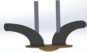
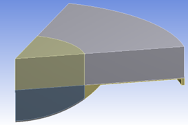
Computational fluid dynamic (CFD) analysis is carried out for six different injection times to study combustion characteristics of diesel engines working with biodiesel fuel. Tables 1 and 2 show the engine specifications and biodiesel fuel characteristics. In this study, a single-cylinder, four-stroke diesel engine with direct injection has been run with biodiesel fuel under engine speed 1500 rpm (Figure 1). Biodiesel fuel extracted from soybean methyl ester was used. For combustion simulations within the engine, the ANSYS FLUENT software has been used. Furthermore, the major governing equations (mass, momentum, energy, and species) were solved using the three dimensions pressure-based implicit unsteady solver. Additionally, the finite volume strategy is employed to compute equation solutions during each time period. In this study, ANSYS FLUENT is based on the pressure correction strategy and employs the PISO algorithm. The momentum, energy, and turbulence equations were solved using a 2nd-order upwind differencing (UD) approach. Also, a model of premixed combustion was utilized to simulate the combustion. The equation of species transport and finite rate chemical reactions were combined with the injection of discrete phase to solve the species. In addition, the upwind scheme has been used for the model equation’s discretization. Concurrently, the RNG k- model was implemented to model turbulence predicated on. The collision model, along with the TAB breakup model, are applied to the spray [18]. Due to the difficulty of the problem, only a 60° sector of the model was defined utilizing 3D software, as shown in Figure 2. The Design Modeler ANSYS tool is used to model the in-cylinder geometry from the closed inlet valve to the open exhaust valve, and grid creation is performed for six different injection times at crank angles of 320,325,330,335,337 and 340 (Figures 2 and 3). Besides that, the flow field for simulation was a chamber of combustion (Figure 2), and the intake valve, exhaust valve, intake port, and exhaust port, were all neglected. 0.0006 kg/s biodiesel fuel was pumped into the end of the compression stroke for ignition.
Table 1. Specification of engine [19]
|
Model |
AV1 (Kirloskar) |
|
Type of engine |
DI diesel |
|
Number of valves |
2 |
|
Cylinders Number |
1 |
|
Stroke (mm) |
110 |
|
Bore (mm) |
80 |
|
Swept volume (litter) |
0.552 |
|
Injector operating pressure (bar) |
220 |
|
Shape of combustion chamber |
bowl in piston |
|
Compression ratio |
16.5 |
Table 2. Characteristics of fuel [20, 21]
|
Biodiesel |
Soybean Methyl Ester |
|
Thermal Conductivity (W/m*K) |
0.158 |
|
Specific Heat (J/kg*K) |
1774 |
|
Density (kg/m3) |
885 |
|
Latent Heat (j/kg) |
229327 |
|
Point of Boiling (K) |
691.69 |
|
Dynamic Viscosity (Pa*s) |
0.006 |
|
Vaporization Temperature (K) |
341 |
|
Stochmetric Air/Fuel Ratio |
12.5 |
|
Critical Temperature (K) |
864.2 |
|
Critical Pressure (Pa) |
1266000 |
|
Binary Diffusivity (m2/s) |
7.42*10E6 |
|
Saturation Vapor Pressure (Pa) |
1329 |
|
Tension of Droplet Surface(n/m) |
0.02715 |
|
Number of Cetane |
51.3 |
|
Critical Specific Volume (m3/kg) |
0.003708 |
2.1 Mechanism of chemical kinetic
The Ansys workbench /FLUENT program is employed to simulate biodiesel combustion. In this study, biodiesel fuel extracted from soybean methyl ester was used. The chemical reaction equation of biodiesel is [22, 23]:
$\begin{gathered}\mathrm{C}_{18.75} \mathrm{H}_{34.55} \mathrm{O}_2+26.3875 \mathrm{O}_2 \rightarrow 18.75 \mathrm{CO}_2+ 17.275 \mathrm{H}_2 \mathrm{O}+\mathrm{Heat}\end{gathered}$ (1)
$\mathrm{H}_2+0.5 \mathrm{O}_2 \leftrightarrow 2 \mathrm{H}_2$ (2)
$\mathrm{CO}+\mathrm{H}_2 \mathrm{O} \leftrightarrow \mathrm{CO}_2+\mathrm{H}_2$ (3)
The emissions of NO are modeled through using extended Zeldovich mechanism. The three chemical formulas that comprise the extended Zeldovich reaction, also called thermal NO, are as follows [24]:
$\mathrm{N}+\mathrm{O}_2 \leftrightarrow \mathrm{O}+\mathrm{NO}$ (4)
$N+O H \leftrightarrow H+N O$ (5)
$N_2+O \leftrightarrow N+N O$ (6)
Figure 1. The engine shape after drawing it with the ANSYS workbench program
Figure 2. A combustion chamber shape with a 60° sector
Figure 3. Combustion chamber meshing domain
2.2 Turbulence model
The turbulent flow was characterized by the variability of velocity field. The well-known RNG k- model was applied to simulate turbulence in this study [25]. The RNG k- model was created using a sophisticated statistical method. The RNG k- model was similar in format to the standard k- model, but it had the benefit of adding the impact of swirl, which was significant for ICE combustion analysis [26]. The transport formulas for the RNG k- Model are as follows:
$\frac{\partial}{\partial t}(\rho k)+\frac{\partial}{\partial x_i}\left(\rho k u_i\right)=\frac{\partial}{\partial x_i}\left[\left(\mu+\frac{\mu_t}{\sigma_k}\right) \frac{\partial k}{\partial x_j}\right]+P_k-p \epsilon$ (7)
$\frac{\partial}{\partial t}(\rho \epsilon)+\frac{\partial}{\partial x_i}\left(\rho \epsilon u_i\right)=\frac{\partial}{\partial x_i}\left[\left(\mu+\frac{\mu_t}{\sigma_\epsilon}\right) \frac{\partial \epsilon}{\partial x_j}\right]+C_{1 \epsilon} \frac{\epsilon}{k} p_\epsilon-C_{2 \epsilon}^* \rho \frac{\epsilon^2}{k}$ (8)
where, $C_{2 \epsilon}^*=C_{2 \epsilon}+\frac{C_\mu \eta^3\left(1-\frac{\eta}{\eta_o}\right)}{1+B \eta^3}$.
2.3 Combustion modeling
This method has been merged with species transports and finite percentage chemistry with streamlined chemistry reactions to predict biodiesel engine combustion characteristics. This method is based on the solving of equations of transport involving the mass fractions of species. The levels of the reactions that appeared as formulas in the species transport equations were also estimated using the Arrhenius rate prevalent expressions [25].
Equation of Arrhenius rate is:
$\dot{\mathrm{R}}_{i, r}=\Gamma\left(\ddot{\mathrm{v}}_{i, r}-\dot{\mathrm{v}}_{i, r}\right)\left(\prod_{i=1}^N\left[C_{i, r}\right]^{\dot{\eta}_{i, r}}-k_{b, r} \prod_{i=1}^N\left[C_{i, r}\right]^{\dot{v}_{i, r}}\right)$ (9)
r denotes the overall impact of third bodies on the reaction rate. This phrase can be written as:
$\Gamma=\sum_i^N \gamma_{i, r} C_i$ (10)
where, γi,r is the efficiency of the third body of j-th species in the r-th reaction.
$k_{i, r}=A_r T^{\beta r} e^{-E_r / R T}$ (11)
where,
Ar is a factor of a pre-exponential (consistent units).
Г is an exponent of temperature (dimensionless).
R is constant of a universal gas (J/kgmol-K).
Er is the reaction's activation energy (J/kgmol).
2.4 Engine ignition modeling
In this research, the method of auto-ignition (model of Harden-burg) was the best option for simulating a direct-injection biodiesel engine. The following formula is the equation of transport for an ignition species Yig [25, 26]:
$\frac{\partial \rho Y_{i g}}{\partial t}+\nabla \cdot\left(\rho \vec{v} Y_{i g}\right)=\nabla \cdot\left(\frac{\mu_t}{S c_t} \nabla Y_{i g}\right)+\rho S_{i g}$ (12)
In which:
Yig is the radical species' mass fraction.
Sctis Schmidt's turbulent number.
$\rho$ is the density of fluid (kg/m3).
Sigis the source expression for the combustion species.
μt is viscosity.
$v$ is the vector of absolute velocity (m/s).
2.5 Spray break up model
The TAB model was employed in this study. The TAB model was built on a comparison between the system of spring-mass and a deforming and oscillating droplet. In the current investigation, the distorting droplet impact was taken into consideration [22, 25]. A damped force oscillator is governed by the following equation:
$F-k x-d \frac{d x}{d t}=m \frac{d^2 x}{d t^2}$ (13)
where, the parameters of this equation and the displacement of the droplet center from its spherical location are determined from Taylor's analogy:
$\frac{F}{m}=C_F \frac{\rho g \mu^2}{\rho \operatorname{ir}}$ (14)
$\frac{\mathrm{k}}{\mathrm{m}}=\mathrm{C}_{\mathrm{k}} \frac{\rho}{\rho \mathrm{ir}^3}$ (15)
$\frac{\mathrm{d}}{\mathrm{m}}=\mathrm{C}_{\mathrm{d}} \frac{\mu_{\mathrm{i}}}{\rho \mathrm{lr}^2}$ (16)
where, ρi and ρa are the densities of discrete and continuous phases, σ is the surface tension of droplets, r is the radius of an undisturbed droplet, μi was the viscosity of the droplet and Vr is the droplet's relative velocity.
2.6 Droplet collision model
Droplet tracking is employed in the model of droplet collision to determine the number of droplet collisions and their findings in an algorithm-accurate way. The model is focused on O'Rourke's strategy, which presumes stochastic collision approximation. When two parcels of droplets collide an algorithm further establishes the type of collision. Only the outcomes of bouncing and coalescence are measured. The prediction of each result was determined using the number of collision Weber and match to the data of experimental. The Weber number was written as follows [25]:
$W_e=\frac{\rho V_r^2 l}{\sigma}$ (17)
where, Vr is the difference in speed between two parcels and l is the two parcels' average geometric diameter.
2.7 Initial and boundary conditions
The simulations initiate at 320 crank angle degrees before TDC and end at 420 crank angle degrees after TDC, covering the stroke of compression and combustion. In addition, the beginning pressure and temperature within the engine should be identified to provide beginning conditions in terms of the governing equations to be solved. Furthermore, the preliminary pressure is 15000000 Pa, while the temperature was 600C. The step of time for each degree of crank angle for the activities was 0.25, implying that four steps of time will be permitted to calculate one degree of crank angle. The small steps of time were chosen to avoid negative densities occurring throughout the computation.
This method has been merged with species transports and finite percentage chemistry with streamlined chemistry reactions to predict biodiesel engine combustion characteristics. This method is based on the solving of equations of transport involving the mass fractions of species. The levels of the reactions that appeared as formulas in the species transport equations were also estimated using the Arrhenius rate prevalent expressions [25].
2.8 Grid generation
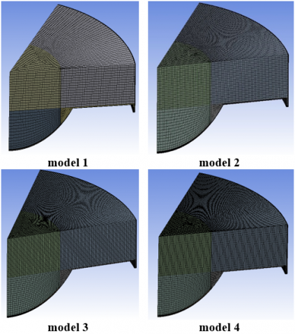
Firstly, the mesh independence evaluation was primed for the AV1 (Kirloskar) diesel engine model. As shown in Figure 4 and Table 3, four various mesh sizes were generated. The simulation was performed for each mesh at a speed of 1500 rpm and the injection time at crank angle 340 to demonstrate the mesh independence test. The calculated cylinder pressure peak inside the chamber of combustion is shown in Figure 5. The results show no discernible difference in the results of pressure peak between the four mesh sizes. Meshing model 3 was selected based on the test of the mesh dependence because it provides extremely accurate findings while minimizing computation time.
Table 3. The mesh-independent test for the engine geometry
|
Cases |
Elements |
Nodes |
|
model 1 |
77870 |
84452 |
|
model 2 |
244612 |
258327 |
|
model 3 |
492928 |
515075 |
|
model 4 |
591763 |
616973 |
Figure 4. The three-size different meshes
Figure 5. Mesh independence verification outcome
2.9 Validation model
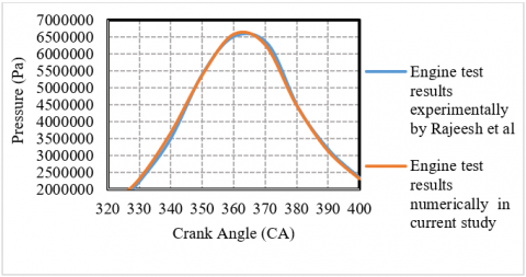
A single-cylinder combustion chamber model was created and simulated for verification. A numerical model of a 3D combustion chamber has been compared with the experimental model of Rajeesh et al. [19]. Comparisons have been made at 1500 rpm speed, a temperature of 300K, and using biodiesel fuel as an alternative to diesel fuel. The cylinder pressure obtained from the numerical analysis has been confirmed by the experimental results of Rajeesh et al. [19]. Figure 6 displays the in-cylinder pressure verification. In overall, simulated results seem to be in good agreement with experimental results at most points Rajeesh et al. [19].
Figure 6. Verification of a single-cylinder combustion chamber model running under biodiesel fuel and at 2000 rpm engine speed
To investigate the impact of injection periods on the engine performance of biodiesel fuel, six different injection times of biodiesel were utilized. The effect of injection periods on biodiesel fuel combustion properties was calculated using ANSYS FLUENT 16. The simulation results on biodiesel engine combustion characteristics are shown below.
3.1 Pressure
Figure 7 demonstrates the relation between the crank angle degree under various fuel injection times and the pressure estimated within the engine. Figure 8 also depicts the engine's highest in-cylinder pressure value at different fuel injection times. As exhibited in Figures 7 and 8, the acceleration of the start of fuel injection raises the peak pressure inside the engine. In addition, the peak pressure would decrease from 17009766Pa to 12906892 Pa, 11823766 Pa, 8744493 Pa, 6766588 Pa and 6603946 Pa for fuel injection times of 40 BTC, 35 BTC, 30 BTC, 25 BTC, 23 BTC, and 20 BTC respectively. This result can be attributed to the fact that the delaying of the start of fuel injection reduces the mixing time between the air and the fuel, consequently decreasing mixture homogeneity. Combustion efficiency, engine performance, and the reduction of the emission of gasses are directly proportional to the degree of mixing homogeneity. In other words, increasing the of mixing homogeneity is directly proportional to the peak cylinder pressure when the biodiesel engine works [27]. Figure 9 depicts the evolution of the Average pressure levels contour within the combustion chamber at different fuel injection times. Figure 9 demonstrates that injecting biodiesel fuel into the engine early improves the distribution of pressure and the placement of its formation inside the cylinder.
3.2 Temperature
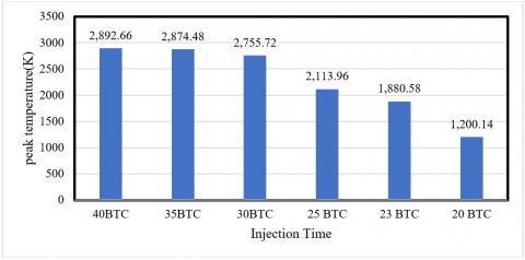
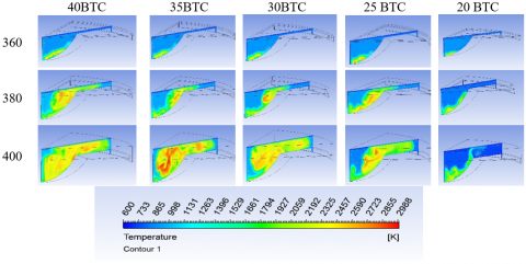
Figure 10 demonstrates the relation between the crank angle degree under various fuel injection times and the temperature estimated within the engine. Figure 11 also illustrates the engine's highest in-cylinder temperature value at different fuel injection times. As shown in Figures 10 and 11, when the start of the fuel injection period is accelerated, the peak temperature inside the chamber of combustion also rises. In addition, the highest temperature in the cylinder would decrease from 2892 K, 2874 K, to 2755 K, 2113 K, 1880 K, 1200 K, and 2790 K for fuel injection times of 40 BTC,35 BTC, 30 BTC, 25 BTC,23 BTC, and 20 BTC respectively. This is due to the fact that accelerating of the start of fuel injection prolongs the blending duration between the air and the fuel, thereby improving mixture homogeneity. Enhancing the combustion process inside the engine is related directly to enhancing the homogeneity of the mixture (air-fuel) inside the engine. Figure 12 reveals the evolution of the Average temperature levels contour within the combustion chamber at different fuel injection times. It exhibits that accelerating at the start of the injection time increases the distribution of temperature and the placement of its creation inside the Biodiesel engine.
Figure 7. Influence of fuel injection times on pressure according to crank angle
Figure 8. Highest pressure within the engine at different fuel injection times
Figure 9. Spatial pattern of pressure
Figure 10. Influence of fuel injection times on temperature according to crank angle
3.3 Nitric oxide emission
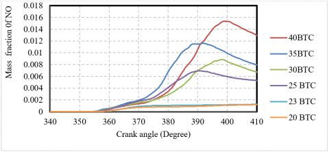
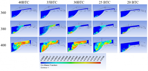
Figure 13 shows the relation between the crank angle degree under various fuel injection times and the nitric oxide emissions estimated within the engine. Figure 14 represents the engine's highest nitric oxide emission value at different fuel injection times. Figures 13 and 14 show that emission levels of nitric oxide rise with acceleration at the beginning of the injection time inside the Biodiesel engine. Additionally, the levels of the nitric oxide mass fraction within the engine decrease from 0.015367293, to 0.011621013,0.008844194, 0.0069317,0.001313656, and 1.13664E-34 for fuel injection times of 40 BTC, 35 BTC, 30 BTC, 25 BTC, 23 BTC, and 20 BTC respectively. This is because the quantity of nitric oxide formed is a function of the cylinder's maximum temperature, retention time, and levels of oxygen. Nitric oxide (NOx) percentage in the chamber of combustion and consequently in the exhaust gas decreases due to the lower combustion temperature [27, 28]. As a consequence, an increase in nitric oxide is deeply linked to the temperature of the engine. Figure 15 displays the NO formation domains under various fuel injection times. As shown in Figure 15, delaying the start of fuel injection has eliminated NO formation.
Figure 11. Highest temperature within the engine at different fuel injection times
Figure 12. Spatial pattern of temperature
Figure 13. Influence of fuel injection times on NO emission rate according to crank angle
Figure 14. Highest NO emission levels within the engine at different fuel injection times
Figure 15. Spatial pattern of NO-emission levels
Figure 16. Influence of fuel injection times on CO emission rate according to crank angle
3.4 CO
Figure 16 shows the relation between the crank angle degree under various fuel injection times and the CO emissions estimated within the engine. Figure 17 represents the engine's highest CO emission value at different fuel injection times. As demonstrated in Figures 16 and 17, CO emissions decrease with delaying of the start of fuel injection timings. Additionally, the levels of the CO mass fraction within the engine drop from 0.133743891 to 0.109591851, 0.109599304, 0.007175804, 0.007094736, and 0.004889395 for fuel injection times of 40 BTC, 35 BTC, 30 BTC, 25 BTC, 23 BTC, and 20 BTC respectively. Delaying the start of fuel injection timings reduced CO emissions slightly. CO emissions are caused by incomplete fuel combustion, which is highly dependent on the air-fuel ratio. Furthermore, engine parameters such as (fuel type, equivalence ratio, engine cylinder design, injection timing, engine speed, and load) impact CO emissions [27, 28].
Figure 18 depicts the evolution of the Average CO levels contour within the combustion chamber at different fuel injection times. Figure 18 also indicates that increasing the retarded fuel injection timings increased CO emission rate within the engine.
Figure 17. Highest CO emission levels within the engine at different fuel injection times
Figure 18. Spatial pattern of CO-emission levels
This study investigates the influence of biodiesel injection timing on combustion process parameters and exhaust gas composition in an AV1 (Kirloskar) diesel engine model operating at 1500 rpm, with biodiesel fuel serving as a substitute for diesel fuel. The engine model was numerically analyzed using ANSYS FLUENT software. The following conclusions were drawn from the findings:
According to the Computational Fluid Dynamics (CFD) results, delaying the onset of the fuel injection period leads to a decrease in both NOx and CO fractions. Specifically, CO levels within the engine dropped from 0.133743891 to 0.109591851, 0.109599304, 0.007175804, 0.007094736, and 0.004889395 for fuel injection timings of 40 BTC, 35 BTC, 30 BTC, 25 BTC, 23 BTC, and 20 BTC, respectively. Similarly, nitric oxide levels within the engine fell from 0.015367293 to 0.011621013, 0.008844194, 0.0069317, 0.001313656, and 1.13664E-34 for the same injection timings.
Moreover, advancing the start of fuel injection enhances the combustion characteristics of the biodiesel engine. The peak pressure decreased from 17009766 Pa to 12906892 Pa, 11823766 Pa, 8744493 Pa, 6766588 Pa, and 6603946 Pa for injection timings of 40BTC, 35BTC, 30BTC, 25BTC, 23BTC, and 20BTC, respectively. In tandem with this, the peak cylinder temperature also decreased from 2892K, 2874K, 2755K, 2113K, 1880K, 1200K, to 2790K for the same range of injection timings.
[1] Bayramoğlu, K., Nuran, M. (2020). Analyzing the effect of fuel injection timing and injection duration on performance and emissions in diesel engines. Journal of ETA Maritime Science, 8(1): 38-52. https://doi.org/10.5505/jems.2020.99705
[2] Mahmood, H.A., Adam, N.M., Sahari, B., Masuri, S. (2018). Development of a particle swarm optimisation model for estimating the homogeneity of a mixture inside a newly designed CNG-H2-AIR mixer for a dual fuel engine: An experimental and theoretic study. Fuel, 217: 131-150. https://doi.org/10.1016/j.fuel.2017.12.066
[3] Nghia, N.T., Khoa, N.X., Cho, W., Lim, O. (2021). A study the effect of biodiesel blends and the injection timing on performance and emissions of common rail diesel engines. Energies, 15(1): 242. https://doi.org/10.3390/en15010242
[4] How, H.G., Masjuki, H.H., Kalam, M., Teoh, Y.H. (2018). Influence of injection timing and split injection strategies on performance, emissions, and combustion characteristics of diesel engine fueled with biodiesel blended fuels. Fuel, 213: 106-114. https://doi.org/10.1016/j.fuel.2017.10.102
[5] Dhahad, H.A., Fayad, M.A., Chaichan, M.T., Jaber, A.A., Megaritis, T. (2021). Influence of fuel injection timing strategies on performance, combustion, emissions and particulate matter characteristics fueled with rapeseed methyl ester in modern diesel engine. Fuel, 306: 121589. https://doi.org/10.1016/j.fuel.2021.121589
[6] Sudarmanta, B., Mahanggi, A.A., Yuvenda, D., Soebagyo, H. (2020). Optimization of injection pressure and injection timing on fuel sprays, engine performances and emissions on a developed DI 20c biodiesel engine prototype. International Journal of Heat and Technology, 38(4): 827-838. https://doi.org/10.18280/ijht.380408
[7] Dharmawan, A.H., Fauzi, A., Putri, E.I., Pacheco, P., Dermawan, A., Nuva, N., Sudaryanti, D.A. (2020). Bioenergy policy: The biodiesel sustainability dilemma in Indonesia. International Journal of Sustainable Development and Planning, 15(4): 537-546. https://doi.org/10.18280/ijsdp.150414
[8] Akhihiero, E.T., Ayodele, B.V., Alsaffar, M.A., Audu, T., Aluyor, E. (2021). Kinetic studies of biodiesel production from jatropha curcas oil. Journal of Engineering, 27(4): 33-45. https://doi.org/10.31026/j.eng.2021.04.03
[9] Salman, S.M., Mohammed, M.M., Mohammed, F.L. (2016). Production of methyl ester (Biodiesel) from used cooking oils via trans-esterification process. Journal of Engineering, 22(5): 74-88. https://doi.org/10.31026/j.eng.2016.05.06
[10] Ahmed, M.J. (2020). Utilization of glycerol for glycerol carbonate synthesis via transesterfication reaction over bio-char catalyst prepared from reed plant. Journal of Engineering, 26(4): 202-211. https://doi.org/10.31026/j.eng.2020.04.14
[11] Banapurmath, N., Tewari, P., Hosmath, R. (2009). Effect of biodiesel derived from Honge oil and its blends with diesel when directly injected at different injection pressures and injection timings in single-cylinder water-cooled compression ignition engine. Proceedings of the Institution of Mechanical Engineers, Part A: Journal of Power and Energy, 223(1): 31-40. https://doi.org/10.1243/09576509JPE673
[12] Tsolakis, A., Megaritis, A., Wyszynski, M., Theinnoi, K. (2007). Engine performance and emissions of a diesel engine operating on diesel-RME (rapeseed methyl ester) blends with EGR (exhaust gas recirculation). Energy, 32(11): 2072-2080. https://doi.org/10.1016/j.energy.2007.05.016
[13] Nwafor, O., Rice, G., Ogbonna, A. (2000). Effect of advanced injection timing on the performance of rapeseed oil in diesel engines. Renewable Energy, 21(3-4): 433-444. https://doi.org/10.1016/S0960-1481(00)00037-9
[14] Jindal, S. (2011). Effect of injection timing on combustion and performance of a direct injection diesel engine running on Jatropha methyl ester. International Journal of Energy and Environment, 2(1): 113-122.
[15] E, J.Q., Pham, M., Deng, Y., Nguyen, T., Duy, V., Le, D., Zuo, W., Pen, Q.G., Zhang, Z.Q. (2018). Effects of injection timing and injection pressure on performance and exhaust emissions of a common rail diesel engine fueled by various concentrations of fish-oil biodiesel blends. Energy, 149: 979-989. https://doi.org/10.1016/j.energy.2018.02.053
[16] Pai, P.S., Rao, B.S. (2011). Artificial neural network based prediction of performance and emission characteristics of a variable compression ratio CI engine using WCO as a biodiesel at different injection timings. Applied Energy, 88(7): 2344-2354. https://doi.org/10.1016/j.apenergy.2010.12.030
[17] Qi, D.H., Leick, M., Liu, Y., Chia-fon, F.L. (2011). Effect of EGR and injection timing on combustion and emission characteristics of split injection strategy DI-diesel engine fueled with biodiesel. Fuel, 90(5): 1884-1891. https://doi.org/10.1016/j.fuel.2011.01.016
[18] Mahmood, H.A., Al-Sulttani, A.O., Mousa, N.A., Attia, O.H. (2022). Impact of lambda value on combustion characteristics and emissions of syngas-diesel dual-fuel engine. International Journal of Technology, 13(1): 179-189. https://doi.org/10.14716/ijtech.v13i1.5060
[19] Rajeesh, S., Methre, J., Godiganur, S. (2021). CFD analysis of combustion characteristics of CI engine run on biodiesel under various compression ratios. Materials Today: Proceedings, 47: 5823-5829. https://doi.org/10.1016/j.matpr.2021.04.193
[20] Nikolić, B.D., Kegl, B., Milanović, S.M., Jovanović, M.M., Spasić, Ž.T. (2018). Effect of biodiesel on diesel engine emissions. Thermal Science, 22(Suppl. 5): 1483-1498. https://doi.org/10.2298/TSCI18S5483N
[21] Al_Dawody, M.F., Bhatti, S. (2014). Experimental and computational investigations for combustion, performance and emission parameters of a diesel engine fueled with soybean biodiesel-diesel blends. Energy Procedia, 52: 421-430. https://doi.org/10.1016/j.egypro.2014.07.094
[22] Ashkezari, A.Z., Divsalar, K., Malmir, R., Abbaspour, I. (2020). Emission and performance analysis of DI diesel engines fueled by biodiesel blends via CFD simulation of spray combustion and different spray breakup models: a numerical study. Journal of Thermal Analysis and Calorimetry, 139(4): 2527-2539. https://doi.org/10.1007/s10973-019-08922-1
[23] Lois, A.L., Al-Lal, A., Canoira, L., Del Campo, M., Lapuerta, M. (2012). PAH occurrence during combustion of biodiesel from various feedstocks. Chemical Engineering Transactions, 29: 1159-1164. https://doi.org/10.3303/CET1229194
[24] Al-Dawody, M., Bhatti, S. (2019). Computational combustion and emission analysis of biodiesel in a variable compression ratio engine. Al-Qadisiyah Journal for Engineering Sciences, 12(3): 184-192. https://www.iasj.net/iasj/article/181704.
[25] Kolhe, A.V., Shelke, R.E., Khandare, S. (2015). Combustion modeling with CFD in direct injection CI engine fuelled with biodiesel. Jordan Journal of Mechanical & Industrial Engineering, 9(1): 61-66.
[26] Mahmood, H.A., Al-Sulttani, A.O., Attia, O.H. (2021). Simulation of syngas addition effect on emissions characteristics, combustion, and performance of the diesel engine working under dual fuel mode and lambda value of 1.6. IOP Conference Series: Earth and Environmental Science, 779(1): 012116. https://doi.org/10.1088/1755-1315/779/1/012116
[27] Reşitoğlu, İ.A., Altinişik, K., Keskin, A. (2015). The pollutant emissions from diesel-engine vehicles and exhaust aftertreatment systems. Clean Technologies and Environmental Policy, 17(1): 15-27. https://doi.org/10.1007/s10098-014-0793-9
[28] Alrazen, H.A., Talib, A.A., Ahmad, K. (2016). A two-component CFD studies of the effects of H2, CNG, and diesel blend on combustion characteristics and emissions of a diesel engine. International Journal of Hydrogen Energy, 41(24): 10483-10495. https://doi.org/10.1016/j.ijhydene.2015.07.097