Abdulkareem Mokif Obais![]()
© 2023 IIETA. This article is published by IIETA and is licensed under the CC BY 4.0 license (http://creativecommons.org/licenses/by/4.0/).
OPEN ACCESS
The Thyristor Controlled Reactor (TCR), an operative reactive power device, is controlled non-linearly in its inductive operational mode, resulting in injection of odd current harmonics. This introduces challenges regarding power quality, which necessitates conditioning of the device. In this study, the development of a continuously and linearly controlled compensating susceptance, constructed from a TCR equipped with harmonic suppression and absorption features, is presented. The series suppression circuitry incorporated within the design consists of a series RLC circuit, resonating at the frequency of the AC source. Simultaneously, the shunt absorption circuitry is specifically designed to eliminate the third and fifth harmonic current components produced by the TCR. This innovative arrangement substantially minimizes the odd harmonics generated by the TCR. In addition, an advanced current controller has been introduced, allowing the reactive current of the proposed susceptance to be linearly controlled in both inductive and capacitive modes. The proposed susceptance was designed and simulated on PSpice, utilizing a 50Hz, 220V AC source. Simulation results demonstrate that the susceptance current reaches its steady-state value within approximately 100ms. Furthermore, the susceptance current in the steady-state region is almost completely devoid of harmonics. Notably, the proposed susceptance displays remarkable linearity during its response to reactive current demands across both inductive and capacitive operational modes. This research provides a significant step forward in addressing the challenges associated with TCR power quality.
harmonic reduction, linear susceptance, power quality, Thyristor Controlled Reactor (TCR), static var compensator
Static Var compensators (SVCs) are commonly utilized to address power quality issues such as poor power factor, harmonic associations, voltage instability, and unbalanced loads. This work provides a comprehensive review of various SVC technologies. Traditional SVCs encompass Thyristor Controlled Reactors (TCRs), thyristor-switched capacitors (TSCs), and Thyristor-Switched Reactors (TSRs). In contrast, power converter-based SVCs include voltage source converter (VSC) based SVCs and Current Source Converter (CSC) based SVCs. Synchronous static compensators, denoted as STATCOMs, are either VSC or CSC based power converters.
A typical shunt SVC was modeled [1] to evaluate its steady-state and step response errors. The results indicated a significant effect of the currents' phase on the steady-state error. A comprehensive overview of various technologies related to the development of devices used in reactive power compensation was introduced [2]. This review discussed different device arrangements spanning from the inception of static Var compensation to 2009.
Prototypes of two FACTS devices composed of a TSR and a TCR were developed and studied within single machine infinite bus and 3-bus systems [3]. The simulation results from [4] demonstrated that the use of a thyristor-controlled series reactor in the transmission network could significantly reduce the flicker levels caused by an arc furnace.
The harmonics associated with TCR operation were mitigated using specific filtering circuits and an efficient current controller [5]. The developed SVC was proposed for load current balancing purposes. Specialized circuits were developed [6] for testing thyristors in FACTS devices. The results revealed that the developed circuits, with suitable protection and control strategies, are capable of successfully testing thyristors used in FACTS.
A harmonic-free TCR configuration was proposed [7] for energy conservation. In this SVC, the TCR was designed to provide continuous and linearly controlled behavior as a purely inductive device. A hybrid passive filter, combining a shunt passive filter with a series passive one, was suggested to overcome the limitations of traditional shunt passive filters [8].
A TCR equipped with a new adaptive current controller and specific filtering circuits was proposed to automatically correct the power factor of an inductive load, eliminating harmonic injection on the AC source side [9]. The optimal design of new topologies of TSRs was suggested [10] to achieve uniformly distributed Var control in power system networks. Protection methods for common static Var compensators were reviewed [11], with event analysis conducted for TCR, TSC, and Harmonic filters, to validate the strengths and weaknesses of typical protection methods.
A novel topology of a TCR power circuit, featuring a delta-connected set of TCRs and a delta-connected set of back-to-back thyristors with a balanced set of reactors, was proposed [12]. An Artificial Neural Network (ANN) was introduced [13] to decrease the total harmonic values resulting from dynamic voltage supply, with the reduction controlled by adjusting the TCR/TSC firing angles. A new TCR topology was proposed, where the harmonics produced by the TCR were minimized through the use of an active power filter [14].
Two TCR topologies were proposed [15] for smooth Var compensation in a low-voltage grid. The first topology was based on a single-core, 3-phase TCR, and the second topology incorporated a separate reactor for each phase. The characteristics of TCR, TSR, and TCS were obtained through the construction of Simulink models for both single and hybrid systems [16]. It was demonstrated that Var compensators constructed from these devices can enhance power quality and power stability in power system networks.
The thyristor-controlled series capacitor (TCSC) was considered in the frequency domain as a harmonic admittance matrix using the Fourier transform of the switching function and terminal voltage [17]. A fast decoupled method was employed [18] to ascertain the voltage on each bus in a power system, with the observed parameters being the power factor (PF), Var, voltage, and the active power. Efficient algorithms based on the Newton-Raphson method were proposed [19] for estimating the firing angle of the FC-TCR Var compensators. A TSC and a TCR were utilized [20] to address power quality issues in Rwanda, with synchronous and PV generators. The study focused on the delays of communication signals and methods to address and identify the failure of the communication system in the grid context.
Sinusoidal pulse width modulation was proposed for controlling a voltage source converter, aiming to avoid the use of additional filters and achieve better harmonic reduction for different types of loads [21]. A voltage-controlled adaptive DC-link was suggested for a thyristor-controlled LC-coupling hybrid active power filter (TCLC-HAPF) to decrease switching noise and loss while improving compensating performance [22]. It was confirmed that the proposed DC-link for TCLC-HAPF resulted in satisfactory compensation performance. It was verified that the STATCOM provides better support than a static Var compensator under faulted conditions due to its ability to provide dynamic compensation to the transmission system [23]. A complete system for Var compensation in high DC power industries or railways was proposed to offer a reliable and technically adaptive solution at a significantly reduced cost [24]. Intelligent methods were proposed to control traditional compensation equipment in distribution grids, ensuring local harmonic and Var compensations in case of low voltage problems in the utility grid [25].
A crucial power quality issue, unbalanced loads, necessitates the use of static compensators comprising linear compensating susceptances controllable in both capacitive and inductive operational modes. This paper proposes a compensating susceptance that is linearly and continuously controlled for load balancing purposes. It is designed to operate in both inductive and capacitive modes without harmonic association, and consists of a TCR equipped with a novel current controller and two harmonic reduction circuits.
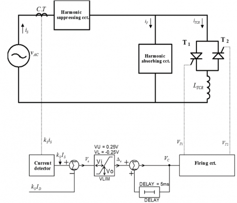
The proposed system scheme is shown in Figure 1. In this figure, the TCR is shunted by a harmonic absorbing circuitry and the resulted parallel configuration is connected in series to a harmonic suppressing circuitry. The harmonic suppressing circuitry is a simple series RLC circuit designed to offer an easy path with negligible impedance to the current fundamental of AC supply. The harmonic absorbing circuit is designed such that it offers easy paths to the most significant odd harmonics released by the TCR. In this design, the third and the fifth harmonics are considered as the most significant odd harmonics. Therefore, the harmonic absorbing circuitry will be built of two series passive harmonic filters connected in parallel. If the supply angular frequency is denoted by ω, then the series third and fifth harmonic filters will resonate at 3ω and 5ω, respectively.
Figure 1. The proposed susceptance scheme
Figure 2 shows the power circuit of the proposed susceptance. The harmonic suppressing circuit is designed such that it resonates at the AC supply frequency angular frequency ω, thus it can be written:
$\omega {{L}_{1}}=\frac{1}{\omega {{C}_{1}}}=\sqrt{\frac{{{L}_{1}}}{{{C}_{1}}}}$ (1)
where, L1 and C1 are the self-inductance and capacitance of the reactor and capacitor forming the harmonic suppressing circuitry. R1 in the harmonic suppressing circuit represents the self-resistance of its reactor.
Figure 2. The power circuit of the proposed susceptance
Since the series third and fifth harmonic filters are designed to resonate at 3ω and 5ω, respectively, then it can be written:
$3\omega {{L}_{3}}=\frac{1}{3\omega {{C}_{3}}}=\sqrt{\frac{{{L}_{3}}}{9{{C}_{3}}}}$ (2)
$5\omega {{L}_{5}}=\frac{1}{5\omega {{C}_{5}}}=\sqrt{\frac{{{L}_{5}}}{25{{C}_{5}}}}$ (3)
where, L3 and C3 are the self-inductance and capacitance of the reactor and capacitor forming the third harmonic filter. L5 and C5 are the self-inductance and capacitance of the reactor and capacitor forming the fifth harmonic filter. R3 and R5 are the self-resistances of the reactors in the third and fifth harmonic filters. The instantaneous currents of the AC source, TCR, and the harmonic absorbing circuit are denoted by iS, iTCR, and iF, respectively. The parameters vAC, LTCR, RTCR are the instantaneous voltage of the AC source, the self-inductance, and the self-resistance of TCR reactor, respectively.
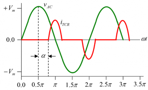
Figure 3a shows a TCR supplied directly from an AC voltage vAC and fired at an angle α as shown in Figure 3b. According to this firing angle, the TCR fundamental current component I1 can be given by [6-9]:
${{I}_{1}}=\frac{{{V}_{m}}}{\pi \omega {{L}_{TCR}}}\left( \pi -2\alpha -\sin \left( 2\alpha \right) \right)$ (4)
where, Vm is the amplitude of vAC and ω=2πf is its angular frequency. I1 can be controlled as follows:
$0\le {{I}_{1}}\le \frac{{{V}_{m}}}{\omega {{L}_{TCR}}} \;\;\;, \text{ for }\frac{\pi }{2}\ge \alpha \ge 0$ (5)
The maximum value of I1 is I1max, which corresponds to zero firing angle (α=0) and can be defined by:
${{I}_{1\max }}=\frac{{{V}_{m}}}{\omega {{L}_{TCR}}}, \;\;\; \text{ }\alpha =0$ (6)
(a) TCR circuit
(b) voltage and current waveforms
Figure 3. The TCR and its associated waveforms
At the fundamental frequency, the circuit of Figure 2 can be closely modeled in frequency domain as shown in Figure 4. In this model, the TCR is replaced by α dependent reactance and the harmonic suppressing circuit is replaced by a short circuit. Note that the all-reactor’s self-resistances are not included in the model due to their negligible effects on the circuit analysis. The peak current IF of the harmonic absorbing circuit at the fundamental frequency and zero firing angle can be computed as follows:
${{I}_{F}}=j{{V}_{m}}\left( \frac{\omega {{C}_{3}}}{1-{{\omega }^{2}}{{L}_{3}}{{C}_{3}}}+\frac{\omega {{C}_{5}}}{1-{{\omega }^{2}}{{L}_{5}}{{C}_{5}}} \right),\text{ }\alpha =0$ (7)
Figure 4. Modeling the proposed susceptance at the fundamental frequency
If L3 and L5 are chosen as identical reactors, then it can be written:
$\omega {{L}_{3}}=\omega {{L}_{5}}=X$ (8)
Solving for ωL3 and ωL5 in Eqs. (2) and (3) results in:
$\omega {{C}_{3}}=\frac{1}{9X}$ (9)
$\omega {{C}_{5}}=\frac{1}{25X}$ (10)
Substituting for Eqs. (8), (9), and (10) into Eq. (7) yields.
${{I}_{F}}=j{{V}_{m}}\left( \frac{1}{8X}+\frac{1}{24X} \right)=j\frac{{{V}_{m}}}{6X},\text{ }\alpha =0$ (11)
Since the proposed susceptance is required to be controlled in capacitive and inductive modes of operation, then the TCR peak current rating should be twice that of the harmonic absorbing circuit at zero firing angle or in other words it can be written:
${{I}_{1\max }}=\frac{{{V}_{m}}}{\omega {{L}_{TCR}}}=2{{I}_{F}}=2\frac{{{V}_{m}}}{6X},\text{ }\alpha =0$ (12)
Or
${{L}_{TCR}}=3{{L}_{3}}=3{{L}_{5}}$ (13)
The harmonic suppressing reactor can be chosen such that:
${{L}_{1}}=0.5{{L}_{TCR}}$ (14)
The kth harmonic current Ik of the actual TCR current is given by [6-9]:
${{I}_{k}}=\frac{{{V}_{m}}}{\omega L}\frac{4}{\pi }\left( \frac{\sin \left( \alpha \right)\cos \left( 2\alpha \right)-k\cos \left( \alpha \right)\sin \left( k\alpha \right)}{k\left( {{k}^{2}}-1 \right)} \;\;\;\; \right)$ (15)
where, k is a positive odd integer greater than unity.
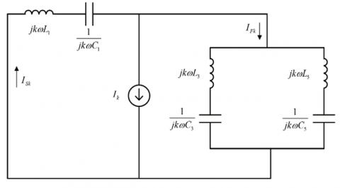
Considering the kth harmonic current defined in Eq. (15), the equivalent circuit of proposed susceptance can be reduced to the circuit shown in Figure 5. In this figure, the TCR is modeled by a current source Ik and the AC voltage supply is replaced by a short circuit. The current ISk represents kth harmonic current component flowing through the AC source side of the proposed susceptance, whereas IFk represents the harmonic current component flowing in the harmonic absorbing circuit. In this equivalent circuit, all reactor’s self-resistances are not included because they are very small and have negligible effects on the circuit analysis.
Figure 5. The kth harmonic equivalent circuit
The impedances of the harmonic absorbing circuitry ZFk and harmonic suppressing circuitry Z1k at the kth harmonic frequency can be determined by:
${{Z}_{Fk}}=\frac{1}{\frac{1}{jk\omega {{L}_{3}}+\frac{1}{jk\omega C{}_{3}}}+\frac{1}{jk\omega {{L}_{5}}+\frac{1}{jk\omega {{C}_{5}}}}}$ (16)
${{Z}_{1k}}=jk\omega {{L}_{1}}+\frac{1}{jk\omega {{C}_{1}}}$ (17)
Substituting for Eqs. (1), (8), (9), (10), (13), and (14) into Eqs. (17) and (18) gives:
${{Z}_{Fk}}=j\frac{X({{k}^{2}}-9)({{k}^{2}}-25)}{2k({{k}^{2}}-17)}$ (18)
${{Z}_{1k}}=j\frac{3X}{2k}\left( {{k}^{2}}-1 \right)$ (19)
It is obvious that the harmonic absorbing circuitry offers zero impedance to both third and fifth current harmonics and inductive impedances to those odd current harmonics beyond the fifth harmonic. Also, the harmonic suppressing circuitry offers very high inductive impedances to all odd current harmonics and almost zero impedance at the fundamental frequency. The kth harmonic current components ISk flowing in the AC source side and IFk flowing in the harmonic absorbing circuitry can be determined by:
${{I}_{Sk}}={{I}_{k}}\frac{{{Z}_{Fk}}}{{{Z}_{1k}}+{{Z}_{Fk}}}\text{ }$ (20)
${{I}_{Fk}}={{I}_{k}}\frac{{{Z}_{1k}}}{{{Z}_{1k}}+{{Z}_{Fk}}}\text{ }$ (21)
Substituting for Eqs. (18) and (19) into Eqs. (20) and (21) gives:
${{I}_{Sk}}={{I}_{k}}\frac{({{k}^{2}}-9)({{k}^{2}}-25)}{3({{k}^{2}}-1)({{k}^{2}}-17)+({{k}^{2}}-9)({{k}^{2}}-25)}\text{ }$ (22)
${{I}_{Fk}}={{I}_{k}}\frac{3({{k}^{2}}-1)({{k}^{2}}-17)}{3({{k}^{2}}-1)({{k}^{2}}-17)+({{k}^{2}}-9)({{k}^{2}}-25)}\text{ }$ (23)
2.1 The TCR current controller
Figure 6 shows the schematic design of the proposed controlling scheme. The susceptance instantaneous current iS is detected by the current transformer (C.T) as kSiS, which is an analog voltage proportional to iS. kS is the proportionality factor of the C.T circuitry. The current detector is a circuit, which detects the instantaneous amplitude IS and polarity of the susceptance current. The output of the current detector is the analog voltage kSIS, which is determined by sampling kSiS at ωt=0. Negative values of kSIS refer to pure inductive currents, whilst positive values refer to pure capacitive currents.
Figure 6. The susceptance controlling scheme
kSIS is compared with kSID, which is a DC analog voltage proportional to the reactive current demand ID. The difference between the instantaneous kSIS and kSID represents the error voltage Ve which is defined by:
${{V}_{e}}={{k}_{S}}\left( {{I}_{D}}-{{I}_{S}} \right)$ (24)
The error voltage Ve is limited by a voltage limiter VLIM to Δe, which is given by:
${{\Delta }_{e}}=0.25{{V}_{e}}$ (25)
This current controller is designed on the basis of delta-modulator principles, where the controlling voltage VC will be built up as long as Δe is positive and starts to decay to zero when Δe is negative. The circuit is designed such that:
$0\le {{V}_{C}}\le +5V$ (26)
The controlling voltage VC governs the TCR firing angle as shown in Figure 7. In this figure, VTRI is a triangular voltage waveform running at the AC supply frequency and synchronized with it. VTRI is compared with VC to produce VT1 which represents the triggering signal of the thyristor T1, while ₋VC is compared with VTRI to produce VT2 for triggering T2. Zero firing angle (α=0) corresponds to VC=0, whereas a firing angle of π/2 (α=π/2) corresponds to VC=5V. The condition of zero firing angle corresponds to maximum inductive current of–IS, while maximum capacitive current of+IS corresponds to α=π/2. The controller forces the susceptance to linearly produce the desired reactive current demand between –IS and +IS.
Figure 7. The TCR triggering mechanism
2.2 Circuit design of the proposed susceptance
The filters of the harmonic absorbing circuitry are designed with high quality factors at their operating frequencies in order that they offer easy paths for their corresponding harmonic current components. A quality factor Q of 30 is a satisfactory choice for both filters. Applying this choice results in:
${{Q}_{3}}=\frac{3\omega {{L}_{3}}}{{{R}_{3}}}=30$ (27)
${{Q}_{5}}=\frac{5\omega {{L}_{3}}}{{{R}_{5}}}=30$ (28)
In this work, a compensating susceptance having a reactive current rating of ±100A (peak value) will be designed to operate on VAC of 50Hz, 220V (rms value). The amplitude Vm of VAC is 311V. The minus sign refers to inductive reactive current, whereas positive sign stands for capacitive current. According to this current rating, the fundamental current IF of the harmonic absorbing circuit is 100A (peak value) and the maximum fundamental I1max of the TCR is -200A (peak value). According to (12)-(14), the following design values are calculated: L3=L5=1.65mH, LTCR=4.95mH, and L1=2.5mH. Using (1)-(3), C1, C3, and C5 are computed as 4050µF, 681.75µF, and 245.43µF, respectively. Using (27) and (28), R3, and R5 are computed as 0.052Ω and 0.0864Ω, respectively. For better and more satisfactory performance, the TCR self-inductance is chosen to have value a bit smaller than the theoretical value to count for its self-resistance. Consequently, the TCR self-inductance and self-resistance are suggested to have the values of 4.5mH and 0.045Ω (R/L=10Ω/H), respectively. Since the reactor L1 holds half the TCR current rating, its self-resistance is proportionally computed as 0.05Ω. The proposed system is designed and tested on PSpice. Figure 8 shows the PSpice design of this compensating susceptance. In this circuit, a current transformer of a current ratio of 1:100 is used. The TCR thyristors T1 and T2 are chosen such that they satisfy its specified current rating. T1 and T2 are of the type SCR 1.2KV, 235A. This thyristor is characterized by the following important voltage and current ratings: Voltage-Off State=1.2kV, Current-On State (It (AV)) (Max)=150A, and Current-On State (It (RMS)) (Max)=235A. The DC voltage source VkSID is proportional to the reactive current demanded from the proposed susceptance. If this source is adjusted to have a value of +5V, this means that a capacitive current of 100A (peak value) is demanded from the susceptance, whilst ₋5V of VkSID means an inductive current of 100A (peak value) is demanded. Zero volts of VkSID corresponds to Zero reactive current demand.
Figure 8. The circuit diagram of the proposed compensating susceptance
First of all, Eqs. (4) and (15) are simulated to show the variations of the normalized TCR fundamental current I1/I1max and the kth harmonic current component Ik/I1max with the TCR firing angle α. Figure 9 shows the normalized TCR fundamental against α, whereas Figure 10 shows the normalized TCR kth harmonic current against α. The most significant odd harmonic currents are I3 and I5, which are intended to be completely cancelled in the AC source side.
The impacts of harmonic suppressing and absorbing circuitries are reflected by the simulations of Eqs. (22) and (23). Figure 11 shows the normalized AC source harmonic current ISk/Ik and the harmonic absorbing current IFk/Ik.
Figure 9. TCR normalized current fundamental against the firing angle α
Figure 10. TCR normalized current harmonics against its firing angle α
Figure 11. The normalized current harmonics flowing in the AC source side and the harmonic absorbing circuitry
Both currents in Figure 11 are normalized to the TCR harmonic current component Ik. In this figure the third and fifth harmonic current components are completely absorbed by the harmonic absorbing circuitry and thus, they disappeared in the AC source side. The harmonic current components beyond the fifth harmonic are significantly reduced in the AC source side.
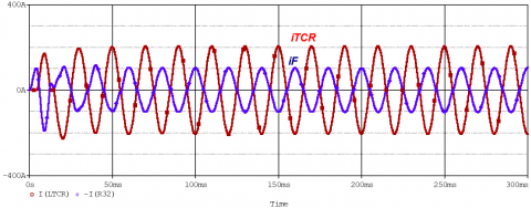
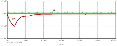
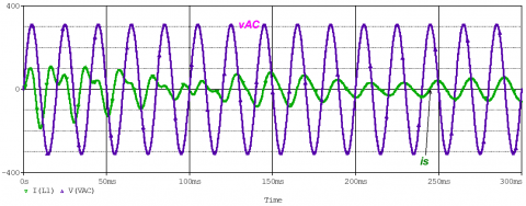
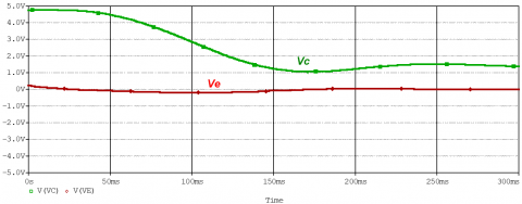
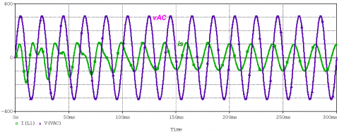
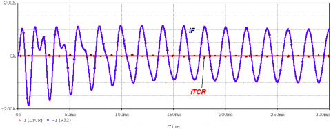
The circuit of Figure 8 was tested on PSpice to show its performance during responding to reactive current demand. The parameters measured in transient and steady states are the AC source instantaneous voltage vAC, the susceptance instantaneous current or the AC source current iS, the error signal Ve, the controlling voltage VC, the instantaneous current iF of the harmonic absorbing circuitry, and the instantaneous TCR current iTCR. The measured parameters in steady states only are the frequency spectrums of the susceptance current IS(f), the TCR current ITCR(f), the harmonic absorbing current IF(f). Firstly, the proposed susceptance was tested during responding to an inductive current demand of -100A (peak value). The minus sign refers to inductive nature of reactive current. The results of this test are shown in Figure 12. Figure 12a reveals the susceptance current iS lagging the AC voltage vAC by an angle of π/2, which verifies that the current is pure inductive as required. Figure 12b states that the TCR is fired at zero angle, thus its current iTCR and the current of the harmonic absorbing circuit iF seem pure sinusoids. Figure 12c shows that the error signal Ve and the controlling voltage VC reach their steady state values within a time of 100msec.
(a) AC source voltage vac and susceptance current iS
(b) TCR current iTCR and harmonic absorbing current iF
(c) Controlling voltage VC and error voltage Ve
Figure 12. The susceptance response to an inductive current demand of -100A (peak value)
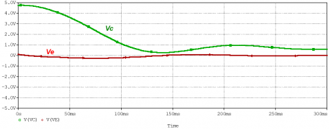
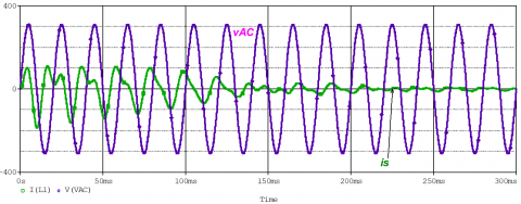
Figures 13-16 show the susceptance responses to peak values of reactive current demands of -50A (inductive), zero, +50A (capacitive), and +100 (capacitive), respectively.
(a) AC source voltage vac and susceptance current iS
(b) TCR current iTCR and harmonic absorbing current iF
(c) controlling voltage VC and error voltage Ve
Figure 13. The susceptance response to an inductive current demand of -50A (peak value)
(a) AC source voltage vac and susceptance current iS
(b) TCR current iTCR and harmonic absorbing current iF
(c) controlling voltage VC and error voltage Ve
Figure 14. The susceptance response to zero current demand
(a) AC source voltage vac and susceptance current iS
(b) TCR current iTCR and harmonic absorbing current iF
(c) controlling voltage VC and error voltage Ve
Figure 15. The susceptance response to a capacitive current demand of +50A (peak value)
(a) AC source voltage vac and susceptance current iS
(b) TCR current iTCR and harmonic absorbing current iF
(c) Controlling voltage VC and error voltage Ve
Figure 16. The susceptance response to a capacitive current demand of +100A (peak value)
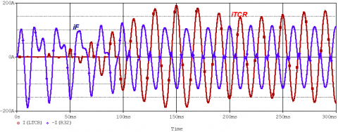
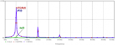
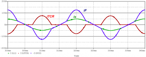
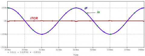
In the above figures, the susceptance current starts approaching its steady-state value within a time of about 100ms. Figures 17-21 show the instantaneous steady-state currents iS, iTCR, and iF during the susceptance responses to peak reactive demands of -100A, -50A, zero, +50A, +100A, respectively. The targeted parameters are the frequency spectrum of the susceptance current IS(f), the frequency spectrum of the TCR current ITCR(f), and the frequency spectrum of the current IF(f), which flows in the harmonic absorbing circuitry. The frequency spectrums of the susceptance current IS(f) in Figures 17-21 certify its pure sinusoidal nature with negligible harmonic association. Therefore, the proposed susceptance has been verified as a harmonic free pure reactive device. It obvious that the susceptance draws almost zero current during responding to zero reactive current demand. Therefore, it can be concluded that the proposed susceptance has zero operational losses and it can be controlled equally in capacitive and inductive operational modes.
(a) The steady-state currents iS, iTCR, and iF
(b) The frequency spectrums of the currents iS, iTCR, and iF
Figure 17. Steady-state response to an inductive current demand of -100A (peak value)
(a) The steady-state currents iS, iTCR, and iF
(b) The frequency spectrums of the currents iS, iTCR, and iF
Figure 18. The susceptance steady-state response to an inductive current demand of -50A (peak value)
(a) The steady-state currents iS, iTCR, and iF
(b) The frequency spectrums of the currents iS, iTCR, and iF
Figure 19. Steady-state response to zero current demand
(a) The steady-state currents iS, iTCR, and iF
(b) The frequency spectrums of the currents iS, iTCR, and iF
Figure 20. The susceptance steady-state response to a capacitive current demand of +50A (peak value)
(a) The steady-state currents iS, iTCR, and iF
(b) The frequency spectrums of the currents iS, iTCR, and iF
Figure 21. The susceptance steady-state response to a capacitive current demand of +100A (peak value)
The linearity of this susceptance is shown in Figure 22, which is plotted using the steady-state responses to reactive current demand in the range of -100A (peak value) to+100A (peak value).
Figure 22. Susceptance steady-state current versus reactive current demand
In this paper, a continuously and linearly controlled susceptance is proposed. This susceptance is designed and tested on PSpice. The simulation results have revealed continuous and linear control in both capacitive and inductive operational modes. The frequency spectrum of the susceptance or AC source current certifies the absence of harmonic current contents in the AC source side. The susceptance current approaches its steady-state value within a time of about 100ms. This promotes the proposed susceptance to be suitable for treating abrupt changes in reactive current demand. Such a proposed susceptance can be exploited in power quality application like load current balancing. The simulation results ensure almost zero no-load operating losses.
[1] Best, R.A., Zelaya-De La Parra, H. (1996). Transient response of a static var shunt compensator. In IEEE Transactions on Power Electronics, 11(3): 489-494. https://doi.org/10.1109/63.491643
[2] Tyll, H.K., Schettle, F. (2009). Historical overview on dynamic reactive power compensation solutions from the begin of AC power transmission towards present applications. In 2009 IEEE/PES Power Systems Conference and Exposition, IEEE, 1-7. https://doi.org/10.1109/PSCE.2009.4840208
[3] Gelen, A., Yalçinöz, T. (2010). Experimental studies of a scaled-down TSR-based SVC and TCR-based SVC prototype for voltage regulation and compensation. Turkish Journal of Electrical Engineering and Computer Sciences, 18(2): 147-158. https://doi.org/10.3906/elk-0907-138
[4] Spasojević, L., Blažič, B., Papič, I. (2011). Application of a thyristor-controlled series reactor to reduce arc furnace flicker. Elektrotehniški Vestnik, 78(3): 112-117.
[5] Obais, A.M., Pasupuleti, J. (2011). Design of a continuously controlled linear static var compensator for load balancing and power factor correction purposes. International Review on Modelling and Simulations, 4(2): 803-812.
[6] Tang, G.F., Zha, K.P., He, Z.Y., Wang, H.T. (2013). Study on operational tests for FACTS thyristor valves. In IEEE Transactions on Power Delivery, 28(3): 1525-1532. https://doi.org/10.1109/TPWRD.2013.2252370
[7] Obais, A.M., Pasupuleti J. (2014). Design of an almost harmonic-free TCR. Research Journal of Applied Sciences, Engineering and Technology, 7(2): 388-395. http://doi.org/10.19026/rjaset.7.266
[8] Zobaa, A.F., Aleem, S.H.E.A. (2014). A new approach for harmonic distortion minimization in power systems supplying nonlinear loads. In IEEE Transactions on Industrial Informatics, 10(2): 1401-1412. http://doi.org/10.1109/TII.2014.2307196
[9] Obais, A.M., Pasupuleti, J. (2014). Automatic power factor correction using a harmonic-suppressed TCR equipped with a new adaptive current controller. Journal of Power Electronics, 14(4): 742-753. http://doi.org/10.6113/JPE.2014.14.4.742
[10] Panfilov, D.I., ElGebaly, A.E., Astashev, M.G. (2017). Design and optimization of new thyristors controlled reactors with zero harmonic content. In 2017 18th International Conference of Young Specialists on Micro/Nanotechnologies and Electron Devices (EDM), IEEE, 491-496. http://doi.org/10.1109/EDM.2017.7981803
[11] Findley, A., Hoffman, M., Sullivan, D., Paramalingam, J. (2017). Lessons learned in static var compensator protection. In 2017 70th Annual Conference for Protective Relay Engineers (CPRE), IEEE, 1-8. http://doi.org/ 10.1109/CPRE.2017.8090035
[12] Maiti, D., Mukhopadhyay, S., Biswas, S.K. (2019). Three‐phase Thyristor Controlled Reactor using two sets of delta connected switches with low current harmonics. IET Power Electronics, 12(15): 4016-4022. https://doi.org/10.1049/iet-pel.2018.5020
[13] Shukla, S., Khan, I., Ali, M.A. (2020). Smart ANN controller for TCR/TSC devices used in power system applications. International Journal of Emerging Trends in Engineering Research, 8(7): 3534-3537. https://doi.org/10.30534/ijeter/2020/106872020
[14] Yan, X.H., Wang, F., Hassan, M.U., Humayun, M. (2020). Harmonic reduction of SVC with system integrated APF. Turkish Journal of Electrical Engineering and Computer Sciences, 28(4): 1916-1931. https://doi.org/10.3906/elk-1909-115
[15] Šapurov M., Bleizgys V., Baskys A., Dervinis A., Bielskis E., Paulikas S., Paulauskas N., Macaitis V. (2020). Asymmetric compensation of reactive power using thyristor-controlled reactors. Symmetry, 12(6): 880. https://doi.org/10.3390/sym12060880
[16] Irokwe N.V., Okoro C.K., Oborkhale L.I., Kanu D. (2021). Comparative analysis of single phase TCR, TSC and TSR static var compensators. Journal of Electrical and Electronics Engineering, 16(4): 59-68.
[17] Kraimia, M.N., Boudour, M. (2021). Harmonic analysis of thyristor controlled series capacitor in polluted Algerian network. International Journal of Energy Technology and Policy, 17(1): 86-97. https://doi.org/10.1504/IJETP.2021.111922
[18] Hardi, S., Rahmat, M., Sinulingga, E.P. (2021). Improved quality of using voltage static var compensator and capacitor bank on the transmission line. In Journal of Physics: Conference Series, IOP Publishing, 1811(1): 012066. https://doi.org/10.1088/1742-6596/1811/1/012066
[19] Terriche, Y., Su, C.L., Lashab, A., Mutarraf, M.U., Mehrzadi, M., Guerrero, J.M., Vasquez, J.C. (2021). Effective controls of fixed capacitor-Thyristor Controlled Reactors for power quality improvement in shipboard microgrids. In IEEE Transactions on Industry Applications, 57(3): 2838-2849. https://doi.org/10.1109/TIA.2021.3058595
[20] Muyizere, D., Letting, L.K., Munyazikwiye, B.B. (2022). Decreasing the negative impact of time delays on electricity due to performance improvement in the Rwanda National grid. Electronics, 11(19): 3114. https://doi.org/10.3390/electronics11193114
[21] Narasimhulu, V., Kumar, D.A., Babu, C.S. (2016). Simulation analysis of switch controlled power filters for harmonic reduction. International Journal of Applied Engineering Research, 11: 7597-7602. https://doi.org/10.37622/IJAER/11.12.2016.7597-7602
[22] Lam, C.S., Wang, L., Ho, S.I., Wong, M.C. (2016). Adaptive thyristor-controlled LC-hybrid active power filter for reactive power and current harmonics compensation with switching loss reduction. In IEEE Transactions on Power Electronics, 32(10): 7577-7590. https://doi.org/10.1109/TPEL.2016.2640304
[23] Barrios-Martínez, E., Ángeles-Camacho, C. (2017). Technical comparison of FACTS controllers in parallel connection. Journal of Applied Research and Technology, 15(1): 36-44. https://doi.org/10.1016/j.jart.2017.01.001
[24] Nikum, K., Wagh, A. (2020). Hardware implementation of step-switched SVCs to correct power factor and mitigate harmonics for large DC variable loads. Journal of the Institution of Engineers (India): Series B, Electrical, Electronics & Telecommunication and Computer Engineering, 101: 777-789. https://doi.org/10.1007/s40031-020-00476-3
[25] Stanelyte, D., Radziukynas, V. (2019). Review of voltage and reactive power control algorithms in electrical distribution networks. Energies, 13(1): 58. https://doi.org/10.3390/en13010058