Hussein Kareem Sultan*![]() | Basim Jabbar Abbas
| Basim Jabbar Abbas![]() | Hussain M. Ashour Al Khuzaie
| Hussain M. Ashour Al Khuzaie![]() | Talib K. Q. Alsheakayree
| Talib K. Q. Alsheakayree![]()
© 2023 IIETA. This article is published by IIETA and is licensed under the CC BY 4.0 license (http://creativecommons.org/licenses/by/4.0/).
OPEN ACCESS
This paper presents a novel design cost optimization approach for reinforced high-strength concrete (HSC) grade T-beams, incorporating the costs of steel, HSC, and formwork within the objective function of the model. Constraint functions are meticulously defined to comply with the ACI 318-08 Code design criteria for structural concrete. Mathematical applications are employed to develop the cost optimization procedure. The utility and effectiveness of the proposed design model and solution strategy are demonstrated through an illustrative problem. The findings from this study suggest that the present strategy, which yields substantial cost savings in utilized building material (concrete and reinforcement steel), offers significant economic advantages over conventional design methodologies. Furthermore, this approach can be extended to other sectors with minimal modifications, thereby enhancing its practical applicability.
high strength concrete (HSC) T-beams, ACI 318-08 code, cost optimum design, nonlinear programming
In the realm of industrial construction, the employment of structural components with T-shaped sections is prevalent, particularly in large-scale and repetitive structures. The preference for these sections stems from their cost-efficiency when optimized design methodologies are implemented, providing substantial advantages to designers and engineers. Notably, the design of T-beam sections often negates the necessity for compression reinforcement, leading to a reduction in the volume of steel required for reinforcement, a major benefit of employing T-beam sections [1, 2].
The advent of modern material technology has facilitated the use of high-strength concrete (HSC), primarily due to its efficiency and economic advantages. The reduction in the volume of building materials precipitates a decrease in weight and foundation costs, thereby making HSC a preferred choice for the construction of concrete foundations [3-7].
Characterized by a high compressive strength ranging from 50 to 100 MPa, HSC offers a multitude of benefits including reductions in story height, member size, concrete volume, and formwork area. A significant disparity is evident in the volume of steel reinforcement when comparing structures built with regular strength concrete to those constructed with HSC [8-18].
The optimization of design processes has been greatly augmented by the evolution of numerical optimization techniques, the availability of robust processing hardware, and the advent of computer-based numerical tools for structural analysis and design. The present research project employs MATLAB application to solve nonlinear programming tasks, converting inequality constraints into equality constraints through the addition of slack variables, thereby constituting a reliable and robust algorithm [19-24].
Despite the growing use of structural optimization of HSC sections across various applications and the inherent uncertainties, the optimal cost design of HSC T-beams remains inadequately explored, and the processes involved are not fully comprehended. This research addresses this gap by employing mathematical applications via the MATLAB program to ascertain the optimal design of HSC T-beams, using a representative problem as an example.
This study introduces a model for determining the optimum cost design of reinforced HSC T-beams under ultimate limit state (ULS) conditions. The objective function includes the costs of steel, HSC, and formwork, which are minimized subject to constraints and strength criteria. The constraint functions are designed to satisfy the design specifications stipulated in the ACI 318-08 design code [25]. The cost optimization technique is developed within the realm of a condensed set of design parameters using a nonlinear program.
The proposed design model and solution approach's applicability is demonstrated by considering a typical two-example problem. The optimized results are compared with conventional design solutions obtained using traditional design methodologies to assess the developed cost model's effectiveness. This work demonstrates that significant reductions in the volume of building materials can be achieved by employing the current methodology to attain optimal solutions. Moreover, compared with traditional design methods used by designers and engineers, the proposed method is practical, reliable, and computationally efficient. It could also be extended to deal with other components without significant modifications.
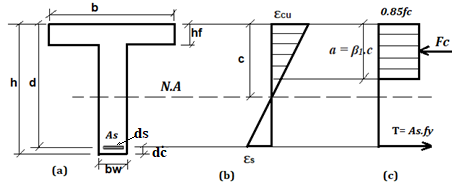
Figures 1-b and 1-c show, respectively, the assumptions employed in the ULS for the stress and strain distributions in the standard reinforced high strength concrete with T-section of beam depicted in Figure 1-a, in accordance with ACI 318-08 code [25].
Figure 1. (a) Typical cross-section of T-beam; (b) strains at the ultimate limit state and (c) stresses at the ultimate limit state
Designers are generally able to determine the optimal design for the structure under consideration thanks to optimization techniques. When it comes to this specific design, the main goal is to reduce the overall cost of the building while still meeting all ACI 318 - 08 regulations. The final structure should not only be inexpensive but also meet all strength and serviceability standards for a specific applied load level. In terms of the design parameters, objective function, and constraint functions, a typical structure optimization problem can be represented mathematically as a nonlinear programming issue.
3.1 Objectives
The objective of optimization problems is to decrease the structure's cost, weight, or volume under specific specified behavior restrictions. In terms of the design variables, objective function, and constraint functions, a typical structure optimization problem can be mathematically formulated as a nonlinear programming problem.
3.2 Optimization of reinforced T-beam
An optimization problem generally takes the form illustrated below:
1) Constant variables are given.
2) Locate the design parameters.
3) Reduce the objective function.
4) Comply with the design restriction.
The following are the constant variables for RC beam design:
3.2.1 Constant parameters (variables)
In this study, reinforced high strength concrete T-beams with several material combinations of concrete grades M55, M75, and M85 and steel grades Fy 420 and Fy 240 were designed optimally. The grade of concrete was chosen as an example (55, 75, and 85 MPa) based on the grade range of high strength concrete in the different codes, which is more than 50 MPa and reach to 100 MPa. Also, the yield stress of the reinforcing steel was also chosen as an example based on the reinforcement steel available in the local markets for longitudinal reinforcing steel bars 420 MPa and 240 MPa for stirrups. Also, because most designers use 420 as yield stress for longitudinal reinforcing steel bars and 240 for stirrups.
According to the most recent market rates, the costs of reinforcement, including rebar work, concrete, and formwork, as well as cost coefficients for 1 m of beam length, were calculated. The costs of concrete in US dollars per m3 and reinforcing steel in US dollars per ton was used in the applications of designing the optimal cost of high-strength reinforced concrete beams with a T-section based on the prices of construction materials in the Iraqi local markets. The cost coefficient values for concrete, steel of different grades, and formwork are: concrete cost (Cc) 135, 138, and 142 \$ /m3 for M55, M75 and M85, respectively, steel cost (Cs) 800 and 750 \$ /ton for for Fy 420 and Fy 240, respectively, formwork cost (Cf) 30 \$/m2.
Constant variables are 4, 6, and 8m span of beam (L), 1.5 m width of flange of beam (b), 0.25 m web width (bw), 2.5, 5, 7.5, 10, 12.5, and 15.0 kN/m live load (ll),10, 20 kN/m dead load (dl), 40 mm effective cover (dc), 2.5 t/m3 specific gravity of concrete ($\gamma$c), 7.85 t/m3 specific gravity of steel ($\gamma$s).
The constant variables (length of beam span (L), live and dead load) in this study were assumed as follows: 4 m was used as the length of the beam with short span and light loads, and the length of 6 and 8 m was chosen as the length of the beam with long span and heavy loads. The live load was used based on its value in the codes and according to the different uses of the buildings. The dead load was chosen approximately based on the thickness of the slab and the loads of the finishing.
3.2.2 Objective function for beam (cost minimization)
The optimization's goal is to reduce the beam's total cost, which includes the cost of both materials and construction. The following equation (objective function) is used to determine the total cost of the T-section of beam per meter of length.
$C_t=C_s\left(A s_1+A s_2\right)+C_c\left(b_w \cdot h+\left(b-b_w\right) h_f\right)+C_f(2 h+b)$ (1)
where, Ct is the cost per meter of length of the beam, Cs, Cc, Cf are constant coefficients that can be defined by the user, $A s_1$ is the longitudinal reinforcement steel area, and $A s_2$ is the transverse reinforcement steel area.
3.2.3 Design variables of beam
The dimensions (height of the beam, h, effective depth of the beam, d) of the T-beam, relative depth of the compressive concrete zone, $\alpha$, the optimal reinforcement ratio, $\rho$, the reinforcement area (tensile, compressive, and shear reinforcement, i.e., area of the longitudinal reinforcement, $A s_1$ and area of the transverse reinforcement, $A s_2$), as well as their placement, are typically related to the design variables in the optimization of reinforced concrete beams. Although they are not frequently used, the material characteristics (such as the steel yield stress ($f y$) and the concrete compressive strength ($f^{\prime} c$)) can also be thought of as variables [26].
Boundaries for design variables. As was mentioned earlier, a few or all of the parameters have boundaries, which result from various factors like the requirements of the code being considered, the aesthetics of the structural members in the constructing, the accessibility of specific sizes of substance at the market place, and the practical considerations. The boundaries taken into account at this research project are listed below.
$d_{\min }=h_{\min }-\frac{d b}{2}-d s-d c, d_{\max }=h_{\max }-\frac{d b}{2}-d s-d c$ (2)
$b_{\min } \leq b \leq b_{\max }$ (3)
$d b_{\min } \leq d b \leq d b_{\max }$ (4)
where, bmin and bmax are selected based on practical and architectural factors, dbmin and dbmax are selected based on the variety of reinforcement readily available on the market, $h_{\min }=\frac{L}{16}$ (is a minimum thickness of beam of ACI – 08 Code), hmax is selected taking into account architectural factors, dc is concrete cover, and ds is diameter of stirrups.
3.2.4 Design constraints of beam
In accordance with the ACI 318-08 design code standards, the following restrictions for the HSC T-beams are established:
Constraints for the ultimate bending strength are as follows:
$M u \leq \phi M n$ (5)
$M u=\frac{W u \cdot L^2}{8}$ (5a)
$M n=A s f y\left(d-\frac{A s f y}{1.7 f c . b}\right)$ (5b)
where, $\phi$ is strength reduction factor (see Figure 2), Mu is factored bending moment, Wu is total distributed load factored=1.2 (Wd + Wsd) +1.6Wl. L is the beam's span, Mn is nominal moment strength in (kN).
Figure 2. Strength reduction factor for shear and bending moment (ACI 318-08) [24]
Minimum and maximum bending reinforcement constraints. The minimal amount of bending reinforcement is determined by the relationship shown in section 10.5.1 of the ACI 318-08 code:
$A s, \min =\frac{0.25 \sqrt{f^{\prime} c}}{f y} \times b w \times d\left(\mathrm{~cm}^2\right)$ (6)
And not less than: $A s \min =\frac{1.4}{f y} \times b w \times d$ (7)
Additionally, the maximum reinforcement ration is stated in Section 10.3.5 of the Code as follows:
$u_{\max }=0.273 \times \frac{f c}{f y} \times\left(\frac{0.003}{0.003+0.004 f y}\quad\right)$ (8)
Constraint on the minimum and maximum shear reinforcement spacing. Following are the maximum and minimum distances between shear reinforcement:
$S v \geq 2.5(\mathrm{~cm}), 0.75 d(\mathrm{~cm})$ (9)
The factored shear force. According to ACI 318-08 building code section 11.1.3.1, the factor shear force is computed at a position of d from face of the supports using the following relationship. Assuming the support's breadth is z (m).
$V u=\frac{\mathrm{Wu} \times\left(L-\frac{\mathrm{z}}{2}-d\right)}{2} \quad(k N)$ (10)
where, Vu is overall shear force generated by the factored loads at a specific portion of the beam, Wu is total distributed load factored, d is the beam's depth, L is the beam's span, and z is the support's width.
The design shear force. Designing beam for shear must be done in accordance with ACI Code 11.1.1, which states that.
$V u \leq \phi V n$ (11)
$V u \leq \phi V c+\phi V s \quad(k N)$ (12)
$V c=0.17 \times \sqrt{f c} \times b \times d$ (13)
$Vn$, a nominal shear strength is equivalent to the combined contribution of the web steel and the concrete ($V n=V C+V s$). Accordingly, for vertical stirrups. $\phi$ is the strength reduction factor=0.75 for shear.
Minimum web reinforcement. The concrete's nominal shear strength contribution is, in accordance with ACI code,
$A v$, min $=0.062 \times \sqrt{f c} \times \frac{b \times s}{f y} \geq 0.35 \times \frac{b \times s}{f y} \quad\left(\mathrm{~cm}^2\right)$ (14)
where, $Av$ is overall web steel cross - section area over a range of distances, $fy$ is web steel's yield strength (MPa), and $S$ is web reinforcement's longitudinal spacing.
Design for shear reinforcement. Shear reinforcement must be provided in cases when $Vu$ is greater than $Vc$, and it must be calculated. ACI section (11.4.7.2) states that the shear reinforcement's strength is given perpendicular to the axis of the RC beam as:
$V_s=\frac{A v \times f y x d}{s} \times 10^{-3} \leq 0.66 \times \sqrt{f c} b d$ (15)
where, $Av$ is transverse reinforcement area in mm2, $S$ is distance between the center-to-center shear reinforcing ties in mm, $Vs$ is given by shear reinforcement is nominal strength in kN.
Deflection control.
$M d \leq 3 M c r, M s \leq 3 M c r$ (16)
The relation of deflection control of beam of ACI - 08 Code are:
$\left[\left(\Delta_i\right) l\right]$ and $\left[2\left(\Delta_i\right)_{d+l}+\left(\Delta_i\right) l\right] \leq$ Limit by ACI 318 – code, where, Md is under service, bending moment only with dead loads, Mcr is bending moment of cracking, Ms is under service, bending moment both dead and living loads $\left(\Delta_i\right)_l=$Deflection immediately caused only by a live load $2\left(\Delta_i\right)_{d+l}=$Long-term deflection brought on by service live and dead loads.
Concrete and steel material costs as well as labor costs (shuttering, pouring of concrete and laying of steel) are included in the cost functions in beam problems. These functions were created using current prices and accepted building industry practices.
The minimum and maximum width and depth, as well as the minimal quantity of longitudinal and shear reinforcements, are the constraints in the beam problem. Other requirements include ductility, deflection, and strength in bending and shear.
The design specifications are mostly based on the ACI 318-08 code. The objective and constraint functions have been created in a way that is appropriate for use with the MATLAB program.
Thus, the mathematical formula, Eq. (1), can be used to determine the reinforced HSC T-beams with the lowest cost.
Find the design variables specified in section (3.4) that minimize the cost function specified in Eq. (1) while taking the design restrictions specified in Eq. (1) through equation 16 into consideration for the provided material attributes, loading data, and constant parameters.
Examples 1 and 2 are a predesigned, HSC T-section of beam that is simply supported at both ends and complies with the requirements of ACI 318-08 design code. They are a part of a bridge deck. Assuming that fy, f’c, ll, dl, b, and bw are constant parameters, then, d, As, and ρ are design parameters.
The following definitions apply to the relevant preassigned parameters of examples: L=4, 6, and 8 m; bf =1.5 m, b=0.25 m, hf =0.1 m, ll=2.5, 5, 7.5, 10, 12.5, 15 kN/m, dc=0.04 m.
Input information for high strength concrete properties: fc=55, 75, and 85 Mpa, γc=1.5, yc=25 kN /m3, Ec =14000 MPa
Input information for steel properties: fy=240 and 420 Mpa, γs=1.15, ys=78.5 kN /m3, Es=210000 Mpa.
Data input for construction material unit costs: Cc=135, 138, and 142$, Cs1=800$, Cs2=750$, Cf=30$.
Example 1: when dead load (dl) =10 kN/m and example 2: when dead load (dl) =20 kN/m.
Descriptions of the origin, formation processes, and application areas of an example are added in the appendix A.
The reinforced high strength concrete beam with T-section is designed using the minimal cost design technique to demonstrate the applicability of the optimal design derived using the present formulation. The detailed design solution for this beam was based on the ACI 318-08 design code. The previously mentioned section contains the predetermined parameters and restrictions. Equation number one is then used to determine the beam's associated total material cost per unit of length.
Tables and graphs are used to display the results of the minimal cost design applications. The outcomes are based on the typical market costs for labor and materials in Iraq in 2020 and 2021.
In actuality, the level of non - linearity of the resultant optimisation issue increases due to the necessity of updating the geometrical dimensions of the segment with the current self of the optimised T-beam, necessitating an iterative procedure to reach the final optimal solution [27].
The ultimate feasible solution vector is achieved in the examples shown only after numerous iterations. The beam width has been set to equal 0.25 m, though, due to practical considerations. This problem can be solved by conducting a one-dimensional search in the d-dimensional space.
Tables 1-3 display the results of utilizing the standard design process to resolve examples 1 and 2. The fy, f’c, ll, dl, b, and bw are constant parameters. And the d, As, and ρ are design variables. The ranges under consideration range between the lowest and maximum ratios of reinforcement steel, allow for changes in the steel reinforcing area (As), effective depth (d), and overall material cost (Ct).
This study examined the effects of live load, concrete grade, dead load, and beam length on the high strength concrete T-section beam's optimum cost. Results of optimum costs and optimum dimensions for the high strength concrete T-section of beam are displayed in Tables 1-3.
The outcomes from the several cases used have demonstrated that the best solutions are not influenced by shifts in the shear stress limitations that can be removed from the issue formulation.
These findings led to the following observations regarding the ideal cost and design variables.
6.1 Effect of live and dead load on optimum cost of HSC T-beam
Tables 1-3 and Figures 3-5 include details of the optimum designs for HSC T- beams carrying dead loads of 10 and 20 kN/m and live loads of 2.5, 5, 7.5, 10, 12.5, and 15 kN/m.
According to Tables 1-3's findings, increasing the live load while maintaining the same beam length and concrete grade has a minimal impact on the optimum cost, optimum reinforcement steel ratio (ρ), and optimum effective depth (d).
The highest optimal cost, corresponded with a 15 kN/m live loads. However, this impact increases when the concrete grade is raised while maintaining the same live load value.
The results showed that maximum cost by mathematically applications on beams, were observed at the concrete grade of 75 and 85 MPa respectively.
The findings in tables also show that raising the dead load significantly affects the outcomes. For the same beam length, concrete grade, and live load, the optimal cost, reinforcing steel ratio (ρ), and effective depth (d) of HSC T-beam all increased as the dead load increased. The highest optimal cost of 4, 6, and 8 m beam length was observed at the 20 kN/m dead load. The effect of dead load on optimal results of beam length 4, 6, and 8 m are presented in Figures 3, 4, and 5 respectively. In general, these results are consistent with those of Ferhat [1] and Fedghouche [18].
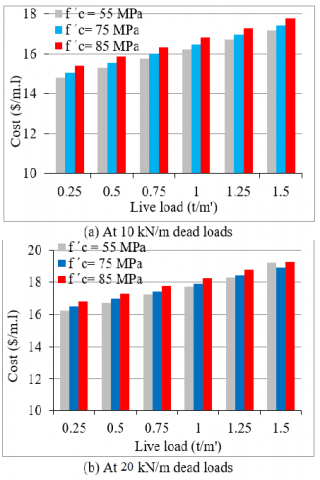
The optimal cost of an HSC T-beam at a dead load of 10 kN/m and a length of 4 m was 14.793, 15.048, and 15.388 at 1.5 kN/m live load and 17.189, 17.436, and 17.766 at 15 kN/m live load when the concrete grade was 55, 75, and 85 MPa, respectively. When the concrete grade is 55, 75, and 85 MPa, respectively, the optimal cost at 20 kN/m rose by about 9.83, 9.61, and 9.33% at 1.5 kN/m live load and by approximately 11.68, 8.44, and 8.29% at 15 kN/m live load.
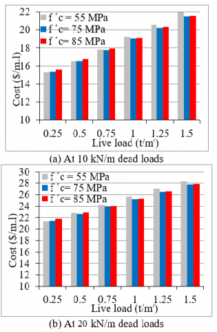
For 1.5 kN/m live load and when dead load increased from 10 to 20 kN/m, the optimum cost of HSC T- beam increased by about 41.15, 40.54, and 40.39%, respectively, at 6 m length of beam and grades of concrete are 55, 75, and 85 MPa. However, at 15 kN/m live load, this optimum cost increased by about 29.15, 29.49, and 29.2%.
The optimal cost of an HSC T- beam increased by about 30.78, 28.79, and 28.5% for 1.5 kN/m live load and when the dead load increased from 10 to 20 kN/m, but by approximately 18.71, 18.63, and 18.09% for 15 kN/m live load at 8 m length of beam and grades of concrete are 55, 75, and 85 MPa.
6.2 Effect of concrete grade on optimum cost of HSC T-beam
When 4 m length of beam, 55 MPa concrete grade, and 10 kN/m dead load, the optimum cost of HSC T-beam is 14.791 \$/m at 1.5 kN/m live load, these costs increased by about 1.72 and 4.02% when the grade of concrete increased to 75 MPa and 85 MPa respectively. But the optimum cost reached 17.189 \$/m at 15 kN/m live load and it increased by about 1.44 and 3.36% when the grade of concrete increased to 75 MPa and 85 MPa respectively. At 20 kN/m dead load, the optimum cost of HSC T-beam reached 16.242 \$/m at 1.5 kN/m live load, these costs increased by about 1.52 and 3.55% when the grade of concrete increased to 75 MPa and 85 MPa respectively. But the optimum cost reached 19.196 \$/m at 15 kN/m live load and increased by about 0.001 and 0.22% when the grade of concrete increased to 75 MPa and 85 MPa respectively. Also, optimal costs increased for the 6 and 8 m beam length when the grade of concrete increased from 55 to 75 MPa and to 85 MPa as seen in Tables 1-3 and Figures 3-5. In general, these results are consistent with those of Ferhat [1] and Fedghouche [18].
6.3 Effect of length of beam on optimum cost of HSC T-beam
At 10 kN/m dead load, when increased the HSC T- beam length from 4 to 6 m, increased the optimal cost of a beam at 15 kN/m live load by approximately 27.69, 23.29, and 21.29% when the concrete grade was 55, 75, and 85 MPa, respectively. However, at 1.5 kN/m live load, no increase in optimal cost was seen. When the length increase from 6 to 8 m, the optimal cost of a beam at 1.5 kN/m live load increased by approximately 42.64, 42.42, and 42.23% when the concrete grade was 55, 75, and 85 MPa, respectively. While, at 15 kN/m live load, the optimal cost increased by approximately 44.69, 45.48, and 46.15%. Also, when the length increase from 4 to 8 m, the optimal cost of a beam at 1.5 kN/m live load increased by approximately 42.55, 41.79, and 40.81% when the concrete grade was 55, 75, and 85 MPa, respectively. While, at 15 kN/m live load, the optimal cost increased by approximately 84.75, 79.36, and 77.27%.
For 20 kN/m dead load, when increased the HSC T- beam length from 4 to 6 m led to increase the optimum cost of beam by about 28.43, 27.65, and 27.13% when the grade of concrete is 55, 75, and 85 MPa, respectively at 1.5 kN/m live load. While, at 15 kN/m live load the optimal cost increased by about 47.66, 47.23, and 44.72%. But, when increased the HSC rectangular beam length from 6 to 8 m led to increase the optimum cost of beam by about 32.16, 30.52, and 30.17% when the grade of concrete is 55, 75, and 85 MPa, respectively at 1.5 kN/m live load. While, at 15 kN/m live load the optimal cost increased by about 32.99, 33.28, and 33.58%. But, when increased the HSC rectangular beam length from 4 to 8 m led to increase the optimum cost of beam by about 69.74, 66.6, and 65.5% when the grade of concrete is 55, 75, and 85 MPa, respectively at 1.5 kN/m live load. While, at 15 kN/m live load the optimal cost increased by about 96.38%, 96.22%, and 93.32%. In general, these results are consistent with those of Ferhat [1] and Fedghouche [18].
Figure 3. Optimum outcomes for the 4 m span beam with a live load
Figure 4. Optimum outcomes for the 6 m span beam with a live load
Figure 5. Optimum outcomes for the 8 m span beam with a live load
Table 1. Results of reinforced HSC T-beams 4 m span length with optimal design of examples 1 and 2
|
(a) f ´c is 55 MPa |
||||||
|
Live Load (t/m') |
10 kN/m Dead Load |
20 kN/m Dead Load |
||||
|
d (cm) |
ρ % |
Cost $/m |
d (cm) |
ρ % |
Cost $/m |
|
|
0.25 |
30 |
0.53 |
14.834 |
30 |
0.83 |
16.247 |
|
0.5 |
30 |
0.63 |
15.305 |
30 |
0.93 |
16.718 |
|
0.75 |
30 |
0.73 |
15.776 |
30.1 |
1.03 |
17.241 |
|
1.0 |
30 |
0.83 |
16.247 |
30.1 |
1.13 |
17.714 |
|
1.25 |
30 |
0.93 |
16.718 |
30.1 |
1.23 |
18.294 |
|
1.5 |
30 |
1.03 |
17.189 |
31.3 |
1.23 |
19.196 |
|
(b) f ´c is 75 MPa |
||||||
|
Live Load (t/m') |
10 kN/m Dead Load |
20 kN/m Dead Load |
||||
|
d (cm) |
ρ % |
Cost $/m |
d (cm) |
ρ % |
Cost $/m |
|
|
0.25 |
30 |
0.53 |
15.081 |
30 |
0.83 |
16.494 |
|
0.5 |
30 |
0.63 |
15.552 |
30 |
0.93 |
16.965 |
|
0.75 |
30 |
0.73 |
16.023 |
30 |
1.03 |
17.436 |
|
1.0 |
30 |
0.83 |
16.494 |
30 |
1.13 |
17.907 |
|
1.25 |
30 |
0.93 |
16.965 |
30.1 |
1.23 |
18.435 |
|
1.5 |
30 |
1.03 |
17.436 |
30.1 |
1.33 |
18.907 |
|
(c) f ´c is 85 MPa |
||||||
|
Live Load (t/m') |
10 kN/m Dead Load |
20 kN/m Dead Load |
||||
|
d (cm) |
ρ % |
Cost $/m |
d (cm) |
ρ % |
Cost $/m |
|
|
0.25 |
30 |
0.53 |
15.411 |
30 |
0.83 |
16.824 |
|
0.5 |
30 |
0.63 |
15.882 |
30 |
0.93 |
17.295 |
|
0.75 |
30 |
0.73 |
16.353 |
30 |
1.03 |
17.766 |
|
1.0 |
30 |
0.83 |
16.824 |
30 |
1.13 |
18.237 |
|
1.25 |
30 |
0.93 |
17.295 |
30.1 |
1.23 |
18.766 |
|
1.5 |
30 |
1.03 |
17.766 |
30.1 |
1.33 |
19.238 |
Table 2. Results of reinforced HSC T-beams 6 m span length with optimal design of examples 1 and 2 when
|
(a) f ´c is 55 MPa |
||||||
|
Live Load (t/m') |
10 kN/m Dead Load |
20 kN/m Dead Load |
||||
|
d (cm) |
ρ % |
Cost $/m |
d (cm) |
ρ % |
Cost $/m |
|
|
0.25 |
30.3 |
1.43 |
15.30 |
31.4 |
1.73 |
21.374 |
|
0.5 |
30.5 |
1.73 |
16.544 |
35.4 |
1.53 |
22.799 |
|
0.75 |
32.2 |
1.83 |
17.811 |
37.3 |
1.53 |
24.238 |
|
1.0 |
37.6 |
1.53 |
19.202 |
40.5 |
1.43 |
25.652 |
|
1.25 |
41.3 |
1.43 |
20.583 |
42.3 |
1.43 |
27.027 |
|
1.5 |
43.6 |
1.43 |
21.948 |
44 |
1.43 |
28.345 |
|
(b) f ´c is 75 MPa |
||||||
|
Live Load (t/m') |
10 kN/m Dead Load |
20 kN/m Dead Load |
||||
|
d (cm) |
ρ % |
Cost $/m |
d (cm) |
ρ % |
Cost $/m |
|
|
0.25 |
30 |
1.43 |
15.358 |
30.4 |
1.83 |
21.467 |
|
0.5 |
30.1 |
1.73 |
16.539 |
30.6 |
2.03 |
22.611 |
|
0.75 |
31 |
1.93 |
17.78 |
34.0 |
1.83 |
23.914 |
|
1.0 |
33.3 |
1.93 |
19.019 |
37.9 |
1.63 |
25.235 |
|
1.25 |
37.3 |
1.73 |
20.236 |
40.8 |
1.53 |
26.515 |
|
1.5 |
41.8 |
1.53 |
21.497 |
44 |
1.43 |
27.836 |
|
(c) f ´c is 85 MPa |
||||||
|
Live Load (t/m') |
10 kN/m Dead Load |
20 kN/m Dead Load |
||||
|
d (cm) |
ρ % |
Cost $/m |
d (cm) |
ρ % |
Cost $/m |
|
|
0.25 |
30 |
1.43 |
15.622 |
30.4 |
1.83 |
21.801 |
|
0.5 |
30 |
1.73 |
16.752 |
30.6 |
2.03 |
22.896 |
|
0.75 |
30.1 |
2.03 |
17.938 |
32.2 |
2.03 |
24.014 |
|
1.0 |
31.5 |
2.13 |
19.117 |
35.7 |
1.83 |
25.339 |
|
1.25 |
34.3 |
2.03 |
20.342 |
38.3 |
1.73 |
26.573 |
|
1.5 |
39.2 |
1.73 |
21.549 |
41.1 |
1.63 |
27.841 |
Table 3. Results of reinforced HSC T-beams 8 m span length with optimal design of examples 1 and 2 when f ´c is
|
(a) f ´c is 55 MPa |
||||||
|
Live Load (t/m') |
10 kN/m Dead Load |
20 kN/m Dead Load |
||||
|
d (cm) |
ρ % |
Cost $/m |
d (cm) |
ρ % |
Cost $/m |
|
|
0.25 |
30.7 |
1.93 |
21.894 |
42.4 |
1.73 |
28.394 |
|
0.5 |
30 |
2.43 |
23.783 |
46.3 |
1.63 |
30.371 |
|
0.75 |
35.7 |
2.03 |
25.783 |
50.4 |
1.53 |
32.302 |
|
1.0 |
40.4 |
1.83 |
27.813 |
52.8 |
1.53 |
34.157 |
|
1.25 |
45.6 |
1.63 |
29.807 |
55.1 |
1.53 |
35.951 |
|
1.5 |
49.7 |
1.53 |
31.756 |
57.3 |
1.53 |
37.697 |
|
(b) f ´c is 75 MPa |
||||||
|
Live Load (t/m') |
10 kN/m Dead Load |
20 kN/m Dead Load |
||||
|
d (cm) |
ρ % |
Cost $/m |
d (cm) |
ρ % |
Cost $/m |
|
|
0.25 |
30 |
2.03 |
22.146 |
37.1 |
2.23 |
28.241 |
|
0.5 |
30.6 |
2.33 |
24.001 |
42.4 |
1.93 |
30.023 |
|
0.75 |
31.8 |
2.53 |
25.883 |
47.2 |
1.73 |
31.772 |
|
1.0 |
36.4 |
2.23 |
27.698 |
51 |
1.63 |
33.565 |
|
1.25 |
40.6 |
2.03 |
29.483 |
55 |
1.53 |
35.326 |
|
1.5 |
45.2 |
1.83 |
31.273 |
55.4 |
1.63 |
37.099 |
|
(c) f ´c is 85 MPa |
||||||
|
Live Load (t/m') |
10 kN/m Dead Load |
20 kN/m Dead Load |
||||
|
d (cm) |
ρ % |
Cost $/m |
d (cm) |
ρ % |
Cost $/m |
|
|
0.25 |
30 |
2.03 |
22.476 |
36.2 |
2.33 |
28.515 |
|
0.5 |
30.6 |
2.33 |
24.337 |
40.2 |
2.13 |
30.236 |
|
0.75 |
31.8 |
2.53 |
26.231 |
44.6 |
1.93 |
31.98 |
|
1.0 |
34.8 |
2.43 |
28.016 |
49.5 |
1.73 |
33.773 |
|
1.25 |
38.7 |
2.23 |
29.772 |
53.2 |
1.63 |
35.451 |
|
1.5 |
42.8 |
2.03 |
31.494 |
57.2 |
1.53 |
37.191 |
This study focused on the creation of T-section beams made of reinforced HSC at the lowest possible cost. The issue was approached analytically using a set of limitations that adhere to the criteria of the ACI code and a least cost design criteria. The fy, f’c, ll, dl, b, and bw are constant parameters. And the d, As, and ρ are design variables. The maximum reinforcement steel ratio is typically used in the conventional design approach to produce the beam cross-section. The study described in this paper comes to the following conclusion:
1) This study suggests a user-friendly way for creating reinforced high strength concrete T-beams that are optimally designed. The MATLAB® computational environment was used throughout the entire computational implementation process.
2) The computer programs and formulas proposed in this work performed satisfactorily in dealing with the challenges of beam design at the lowest possible cost.
3) The actual program is fairly simple to operate, and the results can be understood without the aid of tables or an abacus.
4) The relative costs of concrete, steel, and formwork material, which vary from region to region and over time, have a significant impact on the actual results.
5) With this modeling, the equality and inequality criteria are completely satisfied at the local minimum.
6) The actual outcomes are greatly dependent on the starting setup and the chosen material costs.
7) The optimum cost, optimum reinforcing steel ratio, and optimum effective depth are not significantly affected by raising the live load while keeping the beam length and concrete grade constant. However, as the concrete grade is raised while keeping the live load value constant, this impact increases.
8) Increasing the dead load has a big impact on the results. The optimal cost, reinforcing steel ratio, and effective depth of a high strength concrete T-beam all increased as the dead load increased for the same beam length, concrete grade, and live load.
9) In comparison to other segments that are produced by utilizing the conventional design process, the optimal segment is relatively affordable.
(1) Study optimal design of other types of structural members for reinforced concrete (as a rectangular beam, columns, foundations, and slabs) and structural steel; (2) Optimum design for whole structures.
[1] Ferhat, F. (2018). Design Optimization of Reinforced Ordinary and High Strength Concrete Beams with Eurocode2 (EC-2). Chapter 7 in book Optimum Composite Structures Edited by K.Y. Maalawi, pp. 121- 140. https://doi.org/10.5772/intechopen.78734
[2] Zinkaah, O.H., Sultan, H.K., Al-Rifaie, A., Alridha, Z. (2022). Influence of strut geometry on the size effect of FRP reinforced simply supported deep beams: A theoretical analysis. Mathematical Modelling of Engineering Problems, 9(2): 411-417. https://doi.org/10.18280/mmep.090215
[3] Moreno, J. (1998). High performance concrete: economic considerations. Concrete International, 20(3): 68-70.
[4] Sultan, H.K., Alyaseri, I. (2020). Effects of elevated temperatures on mechanical properties of reactive powder concrete elements. Construction and Building Materials, 261: 120555. https://doi.org/10.1016/j.conbuildmat.2020.120555
[5] Yahy AL-Radi, H.H., Dejian, S., Sultan, H.K. (2021). Performance of fiber self compacting concrete at high temperatures. Civil Engineering Journal, 7(12): 2083-2098. http://dx.doi.org/10.28991/cej-2021-03091779
[6] Assi, L.N., Alsalman, A., Al-Hamadani, Y.A.J., Kareem, R., Al.Khuzaie, H.M.A. (2020). Observations of supplementary cementitious materials effects on the performance of concrete foundation. Earth and Environmental Science, 856(1): 1-11. https://doi.org/10.1088/1755-1315/856/1/012020
[7] Aziz, H.Y., Sultan, H.K., Abbas, B.J. (2021). Simulation and style design of bridge stability supported on large diameter piles. Mathematical Modelling of Engineering Problems, 8(6): 961-966. https://doi.org/10.18280/mmep.080616
[8] Mendis, P., French, C. (2000). Bond strength of reinforcement in high strength concrete. Advances in Structural Engineering, 3(3): 245-253. https://doi.org/10.1260/1369433001502175
[9] Kwan, A.K.H., Au, F.T.K. (2004). Flexural strength ductility performance of flanged beam sections cast of high-strength concrete. The Structural Design of Tall and Special Buildings, 13: 29-43. https://doi.org/10.1002/tal.231
[10] Rashid, M.A., Mansur, M.A. (2005). Reinforced high strength concrete beams in flexure. ACI Structural Journal, 102(3): 462-471. https://doi.org/10.14359/14418
[11] Ozbay, E., Oztas, A., Baykasoglu, A. (2010). Cost optimization of high strength concretes by soft computing techniques. Computers and Concrete, 7(3): 221-237. https://doi.org/10.12989/cac.2010.7.3.221
[12] Barros, M.H.F.M., Martins, R.A.F., Barros, A.F.M. (2005). Cost optimization of singly and doubly reinforced beams with EC2-2001. Structural and Multidisciplinary Optimization, 30: 236-242. https://doi.org/10.1007/s00158-005-0516-2
[13] Ferreira, C.C., Barros, M.H.F.M., Barros, A.F.M. (2003). Optimal design of reinforced concrete T-sections in bending. Engineering Structures, 25(7): 951-964. https://doi.org/10.1016/S0141-0296(03)00039-7
[14] Ceranic, B., Fryer, C. (2000). Sensitivity analysis and optimum design curves for the minimum cost design of singly and doubly reinforced concrete beams. Structural and Multidisciplinary Optimization, 20: 260-268. https://doi.org/10.1007/s001580050156
[15] Kravanja, S., Silih, S. (2003). Optimization based comparison between composite I beams and composite trusses. Journal of Constructional Steel Research, 59(5): 609-625. https://doi.org/10.1016/S0143-974X(02)00045-7
[16] Sultan, H.K., Zinkaah, O.H., Rasheed, A.A., Alridha, Z., Alhawat, M. (2022). Producing sustainable modified reactive powder concrete using locally available materials. Innovative Infrastructure Solutions, 7: 342. https://doi.org/10.1007/s41062-022-00948-z
[17] Sultan, H.K., Al-Husainy, A.S., Anshari, B. (2022). Comparative investigations on reactive powder concrete with and without coarse aggregate. Advances in Engineering Research, Proceedings of the First Mandalika International Multi-Conference on Science and Engineering 2022, 215: 41–54. https://doi.org/10.2991/978-94-6463-088-6_6
[18] Fedghouche, F. (2017). Cost optimum design of doubly reinforced high strength concrete T-beams. Scientia Iranica, 24(2): 476-486. https://doi.org/10.24200/SCI.2017.2411
[19] Schittkowski, K., Zillober, C, Zotemantel, R. (1994). Numerical comparison of nonlinear programming algorithms for structural optimization. Structural Optimization, 7: 1-19. https://doi.org/10.1007/BF01742498
[20] Yeniay, O.A. (2005). A comparative study on optimization methods for the constrained nonlinear programming problems. Mathematical Problems in Engineering, 2005: 181483. https://doi.org/10.1155/MPE.2005.165
[21] Govindraj, V., Ramasamy, J.V. (2005). Optimum detailed design of reinforced concrete continuous beams using genetic algorithm. Computers and Structures, 84(1-2): 34-48. https://doi.org/10.1016/j.compstruc.2005.09.001
[22] Senouci, A.B., Al-Ansari, M.S. (2009). Cost optimization of composite beams using genetic algorithms. Advances in Engineering Software, 40(11): 1112-1118. https://doi.org/10.1016/j.advengsoft.2009.06.001
[23] Kaveh, A., Shakouri, M.A. (2010). Cost optimization of a composite floor system using an improved harmony search algorithm. Journal of Constructional Steel Research, 66(5): 664-669. https://doi.org/10.1016/j.jcsr.2010.01.009
[24] Kaveh, A., Behnam, A.F. (2012). Cost optimization of a composite floor system, one-way waffle slab and concrete slab formwork using a charged system search algorithm. Scientia Iranica Transactions A: Civil Engineering, 19(3): 410-416. https://doi.org/10.1016/j.scient.2012.04.001
[25] ACI Committee. (2008). Building code requirements for structural concrete. ACI 318-08, American Concrete Institute, ACI Committee 318. Farmington Hills, Mich.
[26] Goble, G.G., Moses, F. (1975). Practical applications of structural optimization Journal of the Structural Division, 101(4): 635-648. https://doi.org/10.1061/JSDEAG.0004024
[27] Tiliouine, B., Fedghouche, F. (2010). Optimal design of concrete T-beams under ultimate loads. 2nd International Conference on Engineering Optimization, Lisbon, Portugal, pp. 1-8.