Abbas Allawi Abbas*![]() | Maher Ali Hussein
| Maher Ali Hussein![]() | Tawfeeq N. Hussein
| Tawfeeq N. Hussein![]()
© 2023 IIETA. This article is published by IIETA and is licensed under the CC BY 4.0 license (http://creativecommons.org/licenses/by/4.0/).
OPEN ACCESS
The drilling process using a twist drill tool has high interest in industry, especially in plate metal work. Consequently, during the first penetration through the metal, the sudden stop of the tool at the cutting end or the pulling of the tool from the work piece in the finish can cause crystal nodes to form. This generates torsional torque between the tool and the work piece, which causes torsional shear stress and strain to be translated to the tool root, potentially leading to failure or a dislocated catch region, resulting in hole deformation. So, this paper focuses on how to deal with the increasing stress and strain caused by a sudden stop by using a lubricant liquid that directs flow when a strain gauge attached to the cutting tool detects increasing tool strain. The experimental strain readings in dry conditions and with lubricant liquid are recorded. The Timoshenko equations are used to improve the translation of stress and strain to the tool root and to simulate a torsional case in a cutting tool subjected to torsional torque with the same experimental value (576, 220, 130, 95 N.m.). The results are approximately convergence with a R2 correction factor of 0.9.
experimental study, twist drill, torsional shear stress, sudden stop, lubricant
In the PCFR composite, the polymer with carbon fiber is used to form large holes 15 mm in diameter and 15 mm in thickness. In present research, the material is considered non-homogenous and anisotropic. This material is widely used in the industrial field as assembly parts. Matrix grids, thermal damage, spallation, surface limitation, reducing material, or drawing material out create these holes. Among the deformations that have a negative impact on PCFR composites are the main goal of the present work is to compare holes in twist drills, helical milling, and the technique of pilot hole machining according to the work in one direction for PCFR composites. When compared to other methods, the experimental work shows that the hole made by a twist drill is of lower quality, with the possibility of tool damage at the inlet and outlet. This research resulted in the selection of the best method for repairing holes in the aircraft and automobile industries [1-3].
In the drilling process, two different metals are used as one layer; this technique is widely used in the aerospace industry, and the convergence is very important, especially in different metals due to their differences in properties [4]. The appropriate tool drill for the experimental work is created, and the thrust force is a variable produced on the CFRP or Al 7075 plate hole. The ANOVA method is used to determine the best thrust force value for CFRP/Al 7075, where feed rate is affected by the maximum thrust force analysis. This value led to hole deformation, roughness on the hole surface, and chip formation [5]. The best settings for the drilling tool are 30° for the helix angle, 6° for the initial clearance, 130° for the point angle, 30° for the knife edge angle, 2600 rpm for the rotation speed, and 0.05 mm/rev for the feed rate [6].
The twist drill process is widely used in industry for plate machining. During machining, cutting forces increase with hole diameter, reducing accuracy. When drilling plate material, an axial cutting force is established, resulting in composite convergence and quality reduction [7, 8]. The important thing is to calculate or predict the cutting force value; thus, this paper proposes a method for calculating the cutting force during homogeneous aluminum drilling. When cutting isotropic 6061-T6 alloy, the smoothed particle hydrodynamic is used. The comparison is done between theoretical and experimental results and with another research [9, 10]. The present research is predicting of force cutting according to torsional vibration equation in case firstly mention, this in case of reducing torsional vibration will lead to increase tool life.
The solid carbide tool is used in the drilling process, while the work piece is Al 7075 in experimental cutting. The study deals with important parameters such as cutting speed, federate, and diameter of the cutting tool and investigates the effect of these parameters on thrust force Fz and cutting torque Mz. The response surface methodology is used to show the effect of previous parameters on Fz and Mz, and the ability to increase values during cutting. The applied mathematical model provides positive results and accuracy for 3.5% Fz and 4.8% Mz. The analysis of difference is used to improve the convergence of results. The diameter of the tool and feed rate are important parameters, and they have an effect on the Fz and Mz values, while the speed has a low effect on them in experimental work [11-13].
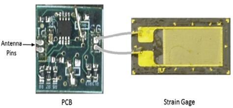
To measure stress wave propagation during percussive drilling, a Whetstone bridge is used to relays the strain gage voltage to the amplifier, which transmits it as analog signal to the ADC. The strain sensor is a uniaxial general-purpose foil resistance strain gage (Omega SGD-13/1000-LY11) with 1000 X resistance, gage factor (GF) of 2.0 and active gage length of 0.5 in. (12.7 mm). This high resistance strain gage is selected to reduce power consumption [14].
The research aims to improve the sudden stop for any reason of a twist drill tool during the cutting process. In other words, the focus of this paper is on treating the increasing stress and strain caused by a sudden stop by using lubricant liquid that directs flow when a strain gauge attached to the cutting tool detects increasing tool strain.
In Experimental work, the work piece may be vibrated or moved during drilling process due to produce low quality hole, or some time the drilling tool faces burl in work piece metal lead to vibrate of cutting tool. In this case can be perform reamer or countersinking process to get high quality hole. The using of good lubricant oil is used to avoid drilling tool for any wear at initial penetrate or process end Depending on torsional vibration equation can be specified important variables effect on dynamic cutting force such as; modulus of rigidity, material density, static shear strain, length of twist drill tool, all these variables, they are changing with position in cross section tool and tool penetration time in metal of work piece.
The drilling process by twist drill is regarded as an important industrial process in mechanical production and in all mechanical parts, as well as maintenance work done on mechanical elements. According to the cutting process on the work piece metal, the stresses and strains will be increased during the increasing of twist drill penetration through the metal work piece, and the temperature will also increase, which can lead to strain hardening occurring in the work piece metal as the temperature rises above the normal limit, particularly during cutting. The stopping of a twist drill occurs on the cross section of the drilling tool due to strain hardening caused by torsional vibration, and this translates to the root of the drilling tool and can lead to tool failure or dislocation of the tool caught region, which leads to hole deformation in a continuous state of cutting. Timoshenko Eqs. (1) and (2) show the dynamic shear strain to static strain ratio, respectively. In these two equations, the mechanical properties and liner velocity can be regarded as practical variables for torsional vibration during the cutting process. The basic of Timoshenko equation according to longitudinal vibration in beam moving liner motion by using second Newton's law and Hooks law. This case can be applied in torsional vibration in initial move or sudden stop as occur in twist drill tool.
$\tau(x, t)=4\left(G \gamma_o\right) \sum_{i=1,3,5}^{\infty} \cos \left(\frac{i \pi x}{2 l}\right) \cdot \frac{1}{i \pi}\left[(-1)^{\frac{i-1}{2}} \cos \cos \left(\frac{i \pi a}{2 l}\right) t+\frac{w}{\gamma_o \cdot a} \sin \sin \left(\frac{i \pi a}{2 l}\right) t\right]$ (1)
$\begin{gathered}\mathrmɣ(x, t)=4 \mathrmɣ_o \sum_{i=1,3,5}^{\infty} \cos \left(\frac{i \pi x}{2 l}\right) \cdot \frac{1}{i \pi}\left[(-1)^{\frac{i-1}{2}}\right. \left.\cos \cos \left(\frac{i \pi a}{2 l}\right)+\frac{w}{\mathrmɣ_o a} \sin \sin \left(\frac{i \pi a}{2 l}\right) t\right]\end{gathered}$ (2)
3.1 Experimental work
The twist drill tool is used, which is made from high-speed steel (HSS) metal from the mechanical industries general company in Babel City. The metal of the twist drill is tested by light spark equipment and its elements, as shown in Table 1. The solid drilling machine BM 20T is used in experimental work it has multi-rotation speeds (25, 65, 110, and 150 rpm). The rectangular strain gauges (type EA-06-120 LZ-120/E) with Antenna as shown in Figure 1 is used to a transmit wireless signal to receiver data connected with interface device of strain reading and connected with a laptop computer to keep the strain readings which transmit from strain gauge (horizontally type), which have frequency (120 Hz) to can be give maximum strain readings. Figures 2 and 3 show the experimental setup of drilling process.
Table 1. The elements percentage of a punch material (HSS)
|
W% |
V% |
Mg% |
Cr% |
C% |
|
6.5 |
1.95 |
4.8 |
3.9 |
0.85 |
Figure 1. The PCB and strain gage [14]
Figure 2. Strain gauge and reading system functional diagram
Figure 3. Experimental mechanical system of twist drill
3.2 Simulation work
The auto desk inventor programme is used to simulate drilling processes by twisting drill tools based on experimental torque values, where the drilling tool experiences sudden stopping due to increasing strain hardening in the work piece metal or crystalline burls in the metal of the drilling tool during the penetration process, and then torsional shear stress occurs in the drilling tool metal and translates to the drilling tool root, which may result in failure. The auto desk inventor improves accuracy according to different velocities of the twist drill tool.
Figures 4, 5, 6, and 7 show the results obtained when using lubricant cutting in the same previous cases The case of lubricant that helps to reduce the cutting force and cooling the cutting area well and improve the condition of cutting by the lubricant fluid as shown its elements in Table 2. In the first of the previously mentioned dry cutting at different speeds, these are simple cases of a sudden stop of the twist drill and then recording the shearing strains due to torsion by emotion of the strain gage, which gives a signal to the receiver via translator and is then saved in a computer programmed on the laptop. In previous figures can be show in 17 second, the intersection is occurred because of strain hardening in drilling tool metal due to increasing of tool penetration in sheet metal.
Table 2. Details of the oil lubricant percentage [15]
|
Stuff |
Office |
Contact: (%Volume/Volume of Fixed Oil) |
|
Fixed oil Washing soap Carbolic acid Sculpture |
Base oil Emulsifier Germicide Extreme |
80% 10% 5% 5% |
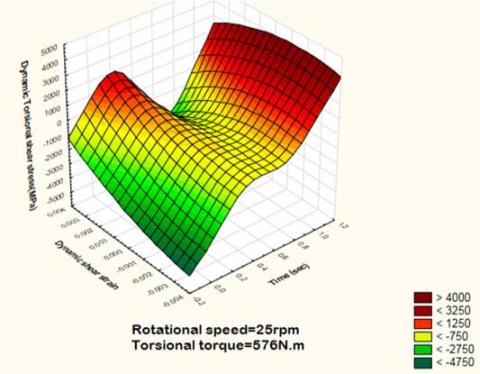
Figure 4. Practical torsional shear strain of twist drill tool at 25rpm and 576N.m
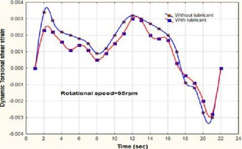
Figure 5. Practical torsional shear strain of twist drill tool at 65rpm and 220N.m
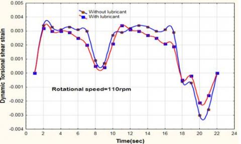
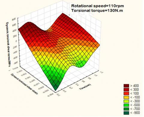
Figure 6. Practical torsional shear strain of twist drill tool at 110rpm and 130N.m
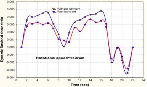
Figure 7. Practical torsional shear strain of twist drill tool at 150rpm and 95N.m
A Visual Fortran programmed can be used to obtain theoretical stress and strain results in order to verify that the torsional stress and strain occur at the root of the tool and draw these results in Figures 8, 9, 10, and 11.
Figure 8. One resonance vibration cycle for twist drill tool to measure (τd & γd) at 576N.m
Figure 9. One resonance vibration cycle for twist drill tool to measure (τd & γd) at 220N.m
Figure 10. One resonance vibration cycle for twist drill tool to measure (τd & γd) at 130N.m
Figure 11. One resonance vibration cycle for twist drill tool to measure (τd & γd) at 95N.m
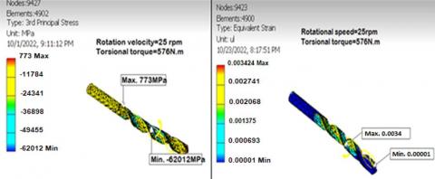
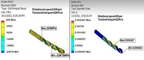
The auto desk inventor programme was used in this study to simulate the drilling process using a twist drill tool based on experimental torque values. The auto desk inventor improved accuracy results as shown in Figures 12, 13, 14, and 15 based on different twist drill tool velocities. to simulate the drilling process using a twist drill tool based on experimental torque values. The auto desk inventor improved accuracy results as shown in Figures 12, 13, 14, and 15 based on different twist drill tool velocities.
Due to the obsolescence of cutting metal, the twist drill drilling process is widely used in industrial production processes, and it will produce strain hardening and crystalline arches in the microstructure of metal, which can have an effect on the tool during the cutting process as torsional stress is inversely proportional to the rotational process of the cutting tool and may then translate this stress to the tool root, leading to failure or causing dislocation.
In experimental work, the first case of dry runs at different speeds will produce strains in the twist drill tool because of torsional torque. In the second state, lubricant liquid is used in the cutting process, resulting in a dabbed reduction in strains and chip slipping facilities due to cutting, as shown in Figures 4, 5, 6, and 7, where the value of experimental strains in dry cutting is 0.0036, 0.0032, 0.0034, and 0.0046, respectively, according to speed sequences of 25 rpm, 65 rpm, 110 rpm, and 150 rpm, and where the maximum strain is as previously stated, the lubricant process is critical when cutting metal with a large thickness.
The lubricant discharge is very important in cutting process, where increasing of discharge in reasonable limit lead to good results to decreasing tool dynamic strain during penetration, can be deal with changing of lubricant discharge and lubricant direction way as variables in feature research.
In the theoretical case, we were applying the Timoshenko Eqs. (1) and (2) in a Visual Fortran programmed and showing the important variables and invariables to get the dynamic stress and strain with different rotational speeds at the same value in experimental work, as illustrated in Figures 8, 9, 10, and 11. The theoretical results of maximum rotational shear strain values (0.0036, 0.0036, 0.0036, 0.0047) and comparison with experimental strains, where the correction factor is (R2=0.9) as shown in Table 3, where this refer to high accuracy between the results. Figures 12, 13, 14, and 15 show auto desk inventor simulation results with the same different speeds, with strain values of (0.0034, 0.002487, 0.003483, and 0.004476) respectively.
Figure 12. Torsional shear stress, torsional shear strain for cutting edge of twist drill at 576N.m
Figure 13. Torsional shear stress, torsional shear strain for cutting edge of twist drill at 220N.m
Figure 14. Torsional shear stress, torsional shear strain for cutting edge of twist drill at 130N.m
Figure 15. Torsional shear stress, torsional shear strain for cutting edge of twist drill at 95N.m
Table 3. The theoretical, experimental and simulation results of shear strain (g) during stroke cutting
|
N (rpm) |
Torque (N.m) |
$\gamma$max. Theoretical |
$\gamma$max. Without Lubricant Experimental |
$\gamma$max. With Lubricant Experimental |
$\gamma$max. Simulation |
|
25 65 110 150 |
576 220 130 95 |
0.0036 0.0036 0.0036 0.0047 |
0.0038 0.0038 0.0038 0.0048 |
0.0029 0.0031 0.0035 0.0038 |
0.0034 0.002487 0.003483 0.004476 |
|
Correction factor (R2) for all results=0.9 |
|||||
Based on the current investigation, some conclusions can be drawn, as shown below:
|
$\tau$ (x, t) |
Dynamic shear stress (MN/m2) |
|
|
G |
Modulus of rigidity (GN/m2) |
|
|
w |
Angular velocity (rad/sec) |
|
|
x |
Position of stress or strain |
|
|
t |
time (sec) |
|
|
a |
Stress speed= $\sqrt{\frac{G}{\rho}}$ |
|
|
Greek symbols |
||
|
$\gamma_o$ |
Static shear |
|
|
$\gamma(\mathrm{x}, \mathrm{t})$ |
Dynamic |
|
[1] Haruna, A.Y., Wang, G.D. (2021). An experimental comparative analysis of twist drilling, helical milling and pilot hole machining for large diameters in CFRPs. Open Access Library Journal, 8(3): 1-19. https://doi.org/10.4236/oalib.1107205
[2] Wang, G.D., Melly, S.K., Li, N., Peng, T., Li, Y.C. (2018). Research on milling strategies to reduce delamination damage during machining of holes in CFRP/Ti stack. Composite Structures, 200: 679-688. https://doi.org/10.1016/j.compstruct.2018.06.011
[3] Balasubramanian, K., Sultan, M.T.H., Rajeswari, N. (2018). Manufacturing techniques of composites for aerospace applications. In Sustainable Composites for Aerospace Applications, Woodhead Publishing, 55-67. https://doi.org/10.1016/B978-0-08-102131-6.00004-9
[4] Hassan, M.H., Abdullah, J., Franz, G., Shen, C.Y., Mahmoodian, R. (2021). Effect of twist drill geometry and drilling parameters on hole quality in single-shot drilling of CFRP/Al7075-T6 composite stack. Journal of Composites Science, 5(7): 189. https://doi.org/10.3390/jcs5070189
[5] Yarar, E., Karabay, S. (2020). Investigation of the effects of ultrasonic assisted drilling on tool wear and optimization of drilling parameters. CIRP Journal of Manufacturing Science and Technology, 31: 265-280. https://doi.org/10.1016/j.cirpj.2020.06.002
[6] Pardo, A., Majeed, M., Heinemann, R. (2020). Process signals characterisation to enable adaptive drilling of aerospace stacks. Procedia CIRP, 88: 479-484. https://doi.org/10.1016/j.procir.2020.05.083
[7] Hussein, M.A., Abbas, A.A., Abdul-Nabe, R.A. (2018). Enhancement the mechanical properties of the deep drawing products through intelligence design and finite element analysis. Journal of Adv Research in Dynamical & Control Systems, 10(13): 2156-2169.
[8] Boldyrev, I.S., Topolov, D.I. (2020). Twist drilling SPH simulation for thrust force and torque prediction. In IOP Conference Series: Materials Science and Engineering, IOP Publishing, 971(2): 022044. https://doi.org/10.1088/1757-899X/971/2/022044
[9] Gaikhe, V., Gaikhe, Y.S., Patil, J.P. (2018). Prediction of thrust force and torque in drilling of glass fiber reinforced plastic using mechanistic force model approach. Procedia CIRP, 77: 187-190. https://doi.org/10.1016/j.procir.2018.08.282
[10] Girinon, M., Valiorgue, F., Karaouni, H., Feulvarch, É. (2018). 3D numerical simulation of drilling residual stresses. Comptes Rendus Mécanique, 346(8): 701-711. https://doi.org/10.1016/j.crme.2018.06.003
[11] Kyratsis, P., Markopoulos, A.P., Efkolidis, N., Maliagkas, V., Kakoulis, K. (2018). Prediction of thrust force and cutting torque in drilling based on the response surface methodology. Machines, 6(2): 24. https://doi.org/10.3390/machines6020024
[12] Kumar, V., Singh, H. (2018). Machining optimization in rotary ultrasonic drilling of BK-7 through response surface methodology using desirability approach. Journal of the Brazilian Society of Mechanical Sciences and Engineering, 40: 1-14. https://doi.org/10.1007/s40430-017-0953-z
[13] Balaji, M., Rao, K.V., Rao, N.M., Murthy, B.S.N. (2018). Optimization of drilling parameters for drilling of TI-6Al-4V based on surface roughness, flank wear and drill vibration. Measurement, 114: 332-339. https://doi.org/10.1016/j.measurement.2017.09.051
[14] Gasco, F., Feraboli, P., Braun, J., Smith, J., Stickler, P., DeOto, L. (2011). Wireless strain measurement for structural testing and health monitoring of carbon fiber composites. Composites Part A: Applied Science and Manufacturing, 42(9): 1263-1274. https://doi.org/10.1016/j.compositesa.2011.05.008
[15] Hussein, M.A., Abbas, A.A., Muslim, N.H. (2022). Experimental and numerical study of different methods' effects on lubricant flow on temperatures and strains of turning cutting tool (HSS). Instrumentation Mesure Metrologie, 21(4): 133-138. https://doi.org/10.18280/i2m.210402