
Ahmed H. Ali*![]() | Abdullah Al-Hussein
| Abdullah Al-Hussein![]() | Fareed H. Majeed
| Fareed H. Majeed![]()
© 2023 IIETA. This article is published by IIETA and is licensed under the CC BY 4.0 license (http://creativecommons.org/licenses/by/4.0/).
OPEN ACCESS
Many global structures, not initially designed to endure seismic forces, necessitate seismic strengthening. Existing research has explored diverse strengthening methodologies and assessed the seismic performance of these solutions. In the present study, a comparative analysis of a structure's seismic behavior before and after strengthening the building's columns was conducted using nonlinear time-history analysis. Two reinforcing techniques, Textile Reinforced Mortar (TRM) and Carbon Fiber Reinforced Polymer (CFRP) jacketing, were applied to a reinforced concrete building. Both techniques aimed to achieve full composite action (full bond) between the jacketing material and the existing concrete columns. The SAP2000 software was employed, strictly adhering to the Federal Emergency Management Agency (FEMA) 356 specifications for beams and column hinges. The analysis treated beam and column elements as nonlinear frame components, defining plastic hinges at their respective ends to simulate their behavior. Specifically, the beams were modeled to only possess moment (M3) fiber hinges, while columns were designed to accommodate axial load and biaxial moment (PMM) fiber hinges. The numerical findings indicated an average increase of 8% and 5% in base shear for buildings strengthened with CFRP and TRM jackets, respectively, when compared to non-strengthened buildings. Maximum story displacement increased by 9% and 4% correspondingly when the building was enhanced with CFRP and TRM jackets, compared to the original structure. It is noteworthy that both methods required a similar number of columns to be strengthened, yet the total cost of CFRP was found to be approximately 35% higher than that of TRM.
strengthening, Textile Reinforced Mortar jacketing, Fiber Reinforced Polymer wrapping, seismic, SAP2000
It has been observed that numerous old buildings, constructed according to previous design code standards, are prone to seismic damage. This fact becomes increasingly evident with each occurrence of a major earthquake, as similar patterns of damage repeat themselves. Previous earthquakes have revealed that many substandard structures do not manage to withstand significant seismic events, indicating that vulnerability is not limited to a few specific building types. Factors such as building design, size, local ground conditions, and construction quality have all been proposed as potential explanations. Unlike conventional structural design that primarily considers gravity loads, seismic design takes into account the possibility of building damage following a substantial earthquake. Building codes mandate that structures possess sufficient strength to withstand both strong earthquakes and minor seismic activities without collapsing [1]. The structural design must combine fundamental lateral-force resistance strength with suitable structural details and sufficient ductile connections between the structural elements to achieve this purpose [1]. Many personal homeowners, and significant industries, including government organizations, have chosen to rehab existing buildings rather than construct new ones due to the high cost of new construction and the historical significance of old structures. Governmental organizations have responded by adopting a law that requires seismic strengthening. There is a need for specific evaluation and strengthening standards for existing buildings. As evidenced by the designers' awareness of potential damage and according to their knowledge and experience, there is a high possibility of damage in older, non-code-compliant buildings, which sometimes perform not so well in significant earthquakes. As a result, it has become important to strengthen buildings in numerous ways. Using Carbon Fiber polymer in different forms is one of the simplest, quickest, and most cost-effective ways to do this. In a study conducted by Youm et al. [2] in 2007, it was observed that the utilization of Glass Fiber Reinforced Polymer (GFRP) wrapping significantly improves the ductility, capacity, and energy dissipation of reinforced concrete (RC) columns. Additionally, the seismic performance of RC columns with insufficient lap splices was enhanced through the application of GFRP wrapping. The study presented by Pantelides et al. [3] in 2008 showed that it is possible to improve the seismic behavior of beam-column joints of insufficient seismic features using CFRP jacketing. This solution demonstrated that improving joint shear strength and inelastic rotation capacity leads to enhanced structural performance in seismic events. On the other hand, it was observed that GFRP exhibited greater ductility compared to CFRP. In a study conducted by Bournas et al. [4] in 2009, it was found that Textile Reinforcement Mortar (TRM) jacketing is highly effective in enhancing the cyclic deformation ability and dissipation of energy for old type reinforced concrete columns with inadequate detail. The study also indicated that TRM jacketing is comparable to its Fiber Reinforced Polymer (FRP) counterpart in terms of its effectiveness in improving the performance of these columns. According to a study by Ronagh and Eslami [5] in 2013, both composite materials, CFRP and GFRP, showed enhancements in terms of their lateral carrying capacity. However, CFRP demonstrated twice as much improvement as GFRP. Ismail [6] 2014 showed that the columns can be jacketed with CFRP sheets to achieve significant lateral displacement and slightly higher lateral strength. Steel jackets were able to achieve more lateral strength and displacement. The lateral stiffness, strength, and lateral displacement capacity were all improved by the reinforced concrete jacketing. Khlef et al. [7] 2022 conducted a numerical study to show the effectiveness of Ferro cement jacket, CFRP jacket, and steel jacket strengthening techniques. The findings of the study showed that each strengthening method is capable of withstanding earthquake loads. The previous studies focused on the practical implementation of the strengthening method and mainly focused on symmetrical buildings while none of these studies discussed the cost of retrofitting the structure. As there were a few theoretical simulations of the strengthening of buildings under seismic load and the majority of these studies used nonlinear static analysis. In addition, only a few researches have investigated and compared the general behavior of strengthened RC structures with TRM and CFRP. This paper deals with the seismic behavior of buildings that are strengthened with two different techniques (TRM and CFRP) jackets. The analysis is conducted using the nonlinear time-history method. The building considered in this study is vertically unsymmetric.
One successful strategy for improving a structure's overall performance, particularly when faced with severe lateral forces such as ground movement, is to increase the deformational capacity of the structural components. To attain this goal, the following measures can be implemented [8]:
Seismic analysis, which is a subgroup of structural analysis, refers to the estimation of structural response to earthquakes. It plays a vital role in the structural design, earthquake engineering, and evaluation of structures in areas prone to seismic activity. This analysis can be categorized into various types [9], based on the nature of external forces and the resulting structural behaviors: linear and nonlinear static and dynamic analysis. In the case of regular structures with a finite height, one can employ linear static analysis (or an equivalent static approach) to evaluate their behavior. Linear dynamic analysis, on the other hand, can be conducted using the response spectrum approach. The intensity and the distribution of the forces over the structure height are the key distinctions between linear static analysis and linear dynamic analysis. The most efficient and logical approach for determining the dynamical response of structures subjected to earthquakes is a nonlinear dynamic analysis, sometimes referred to as a nonlinear time-history analysis [9].
2.1 Nonlinear dynamic analysis
This technique has proven to be very useful in structural seismic analysis, particularly when evaluating nonlinear structural responses. It is necessary to have a representative earthquake time history in order to assess the structure in this study. During a time history analysis, a structure is examined step-by-step to determine its dynamic response to specific loading [9]. For each time interval, the displacement, plastic deformation, and internal forces that occurred in the system are computed, and their highest values must be noted during an earthquake. The dynamic system's equilibrium equation is provided by:
$\mathrm{K} u(\mathrm{t})+\mathrm{C} \dot{u}(\mathrm{t})+\mathrm{M} \ddot{u}(\mathrm{t})=\mathrm{r}(\mathrm{t})$ (1)
where,
C: viscous damping matrix, which represents the energy dissipation in the real structure.
K: stiffness matrix of the whole structural system.
u(t), $\dot{u}(\mathrm{t})$ and $\ddot{u}(\mathrm{t})$: the absolute displacement, velocity, and acceleration vectors, respectively.
r(t): earthquake load vector.
Either modal integration or direct integration can be used to solve Eq. (1) [9]. Due to the direct application of seismic loads to the structure, time history analysis is preferred for assessing structural behavior.
The technique is based on direct numerical integration of differential equations of motion and takes into account the elastic-plastic deformation of a structural member [9].
2.2 Nonlinear direct integration method
The most popular approach for the dynamic analysis of structural systems is the direct-integration method, which solves the dynamic equilibrium equations step-by-step at equal time intervals (Δt, 2Δt, 3Δt, etc.) [10]. This method determines the dynamic response of the structure to the ground motion of an earthquake by applying a time-dependent force function. Two different kinds of nonlinearity are considered by the nonlinear analysis [10]:
1-Material nonlinearity, in which the stress-strain relation takes the form of a nonlinear complicated function.
2-Geometric nonlinearity (P-delta effect), where the equilibrium equations account for the deformed configuration of the structure.
The Hilber-Hughes-Taylor method and the Newmark time integration approach are two of the methods for solving nonlinear dynamic equations that are available in the SAP2000 program. To approximate the Newmark approach, the Hilber-Hughes-Taylor method uses a finite difference in the time interval (t). It follows that:
$\left\{\dot{u}_{\mathrm{t}+\Delta t}\right\}=\left\{\dot{u}_t\right\}+\left[(1-\gamma)\left\{\ddot{u}_t\right\}+\gamma\left\{\ddot{u}_{\mathrm{t}+\Delta t}+\Delta t\right\}\right] \Delta t$ (2)
$\begin{gathered}\left\{u_{t+\Delta t}\right\}=\left\{u_t\right\}+\left\{\dot{u}_t\right\} \Delta t+\left[(1 / 2-\beta) \left\{\ddot{u}_t\right\}+\beta\left\{\ddot{u}_{t+\Delta t}\right\}\right]\Delta t^2\end{gathered}$ (3)
∆: time interval.
{$u_t$}, {$\dot{u}(\mathrm{t})$} and {$\ddot{u}(\mathrm{t})$}: vectors of nodal displacement, velocity and acceleration, respectively at time t.
{$u_{t+\Delta t}$} and {$\dot{u}_{t+\Delta t}$}: vectors of nodal displacement and velocity at time ($\mathrm{t}+\Delta \mathrm{t}$).
The numerical damping could be included in the equation of motion without impacting accuracy as follows:
$[M]\left\{\ddot{u}_t\right\}+(1+\alpha)[C]\left\{\dot{u}_{t+\Delta t}\right\}+(1+\alpha)[K]\left\{u_{t+\Delta t}\right\}=(1+\alpha) F_{t+\Delta t}-\alpha F_{t+\Delta t}+[C]\left\{\dot{u}_t\right\}+\alpha[K]\left\{u_t\right\}$ (4)
For (α = 0), the method is reduced to the Newmark method. Therefore, the dynamic Eq. (1) at a time ($\mathrm{t}+\Delta \mathrm{t}$) is evaluated as:
$[M]\left\{\ddot{u}_{t+\Delta t}\right\}+[C]\left\{\dot{u}_{t+\Delta t}\right\}+[K]\left\{u_{t+\Delta t}\right\}=-[M]\left\{a_{t+\Delta t}\right\}$ (5)
The displacement solution at time (t+∆t) is determined by first rewriting Eqs. (2) and (5) such that:
$\left\{\ddot{u}_{t+\Delta t}\right\}=a_0\left[\left\{u_{t+\Delta t}\right\} -\left\{u_t\right\}\right]-a_2\left\{\dot{u}_t\right\} -a_3\left\{\ddot{u}_t\right\}$ (6)
where:
$\begin{gathered}a_0 =\frac{1}{\beta \Delta t} \\ a_1 =\frac{\gamma}{\beta \Delta t} \\ a_2 =\frac{1}{\beta \Delta t} \\ a_3= 1 / 2 \beta-1 \\ a_4=\gamma / \beta-1 \\ a_5=\frac{\Delta t}{2 \left(\frac{\gamma}{\beta}-2\right)}\end{gathered}$
Noting that Eq. (5) which expressed {$\ddot{u}_{t+\Delta t}$} can be substituted into Eq. (4). Eqs. (2)-(3) can be rewritten in term of the unknown displacement {$u_{t+\Delta t}$} and combined with Eq. (6) to configure the following equation:
$\begin{gathered}\left([M]+ a_1[C]+[M]\left\{u_{t+\Delta t}\right\}=-[M]\left\{a_{t+\Delta t}\right\}+\right. {[M]\left(a_0\left\{\mathrm{u}_t\right\}+a_3\left\{\ddot{\mathrm{u}}_t\right\}\right)+\left[C]\left(a_1\left\{u_t\right\}+ a_4\left\{\dot{\mathrm{u}}_t\right\} +\right.\right.} \left.a_5\left\{\ddot{\mathrm{u}}_t\right\}\right)\end{gathered}$ (7)
Eqs. (1) and (5) are used to estimate velocities and accelerations once a solution for displacement {$u_{t+\Delta t}$} has been found. The Hilber-Hughes-Taylor technique employs the following fixed value for ($\gamma$ and $\beta$):
$\gamma=\frac{1}{2}-2 \alpha, \beta=\frac{1}{4}(1-\alpha )^2$ (8)
For (α=0), the values of ($\gamma$ and $\beta$) are equal to (0.5) and (0.25), respectively, which are equivalent to the constant acceleration method [11].
The building under discussion in this work is a 6-story RC building with plan dimensions of 15 m×20 m and a story height of 3.5 m as illustrated in Figures 1 and 2. This type of building is a typical building structure that is built for commercial use in Iraq under normal structural loading and is typically not designed for seismic effect. The average thickness of the slabs is 150mm. The typical dimensions of beams are 0.3m×0.5m with a length of 5m. The longitudinal reinforcement used at the top and bottom of the beams is 4Ø16mm and 3Ø16mm, respectively. The dimensions of the columns are 0.45m×0.45m with the longitudinal reinforcement 8Ø25mm and ties Ø10mm@300mm. The longitudinal and transverse reinforcement of all the sections are sufficient for gravity loadings; however, they may not be sufficient for seismic loading. The longitudinal and transversal reinforcements in the columns are considered to be constant along the height of the building. The reinforcement at the top and bottom of the slabs is 10mm@100mm. The assumed damping ratio is 5%. A dead load includes selfweight and uniform distributed load of (2 kN) and a live load is (4 kN) on each story. Furthermore, the El Centro earthquake is considered in this study. The earthquake was with a moment magnitude of 6.9 and was classified as an X (Extreme) on the Mercalli intensity scale. It was significant because a strong-motion seismograph was able to record an earthquake near a fault rupture for the first time. The earthquake was considered a moderate-sized event with a complex energy release signature and was the strongest earthquake on record to hit the Imperial Valley. The building subjected to seismic loadings in either the X-direction or the Y-direction is analyzed using the nonlinear time history approach with the help of SAP2000.
As SAP2000 software has high modeling capabilities, it is powerful general software for analyzing and designing various types of structures. A variety of structures can be analyzed using this software, including buildings, bridges, tanks, trusses, and many others. Static and dynamic analysis of a structure can be performed with this software. SAP2000 is able to generate and apply seismic loads automatically based on various domestic and international codes.
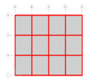
Figure 1. Plan view of the building

Figure 2. 3-D view of the building
4.1 Fiber Reinforced Polymer
A polymer matrix reinforced with fibers makes up the composite material known as fiber-reinforced polymer (FRP). Typically, the fibers are made of carbon FRP (CFRP), glass FRP (GFRP), or in very rare cases, basalt. Due to their high tensile strength and low weight in comparison to traditional steel, FRP materials are frequently used as external reinforcement on existing RC elements to increase their flexural and shear strength [12]. It should be highlighted that strengthening structural members with FRPs does not modify their stiffness or the distribution of stiffness over the entire structure, despite the fact that it significantly enhances their strength [12].
4.2 Textile Reinforced Mortar
TRM mixes an inorganic matrix, most commonly a cement or lime-based mortar, with high-strength textiles arranged in the form of open meshes. TRM may be placed on a wet surface or at low temperatures, and it is inexpensive, safe for manual workers, resistant to high temperatures, and compatible with masonry and concrete materials. Due to all these factors, using TRM instead of the more popular FRP is becoming increasingly acceptable for strengthening structures [13]. Considering the limitations of FRP systems, it could be difficult for the composite and the masonry to work together. They are also distinguished by a lack of ductility, properties, installation problems associated with the thermosetting adhesive's moisture and temperature dependence, the resin's toxicity, and the need for skilled workers. It appears that strengthening typical or historic masonry structures with TRM holds a lot of potential. The initial uses of TRM systems were in concrete elements. Typically, a textile mesh material is a reinforcement for TRM composite material and it is composed of fiber rovings arranged in multiple directions [10]. To form a mesh, the fiber rovings are separated from one another. The fiber roving's holes enable the reinforcement and matrix to mechanically connect. When non-metallic textiles are coated with polymers, both the stability and mechanical interaction are improved. As a composite material, the mortar composition utilized in the TRM system plays an important role in its performance, since fiber impregnation is important to achieve good bonding between the fibers and the matrix. Because cement-based mortar has the necessary fine granules, plastic uniformity, good workability, low viscosity, and suitable shear strength, it is frequently utilized as a matrix in TRM. The flexural strength and the bond between materials are two examples of the mechanical properties of mortar. Polymers can be added to considerably enhance the matrix and fiber rovings [11].
4.3 Material properties
The properties of concrete, reinforcing steel and strengthening materials considered in this study are listed in Table 1.
Table 1. Material properties
|
Compressive strength of concrete, f′c |
35 MPa |
|
Yield strength of steel, f y |
420 MPa |
|
Compressive strength for mortar |
52 MPa |
|
CFRP composite system (Tyfo SCH-41S) |
Unidirectional CFRP sheet |
|
Modulus of elasticity of CFRP in primary fibers direction |
77.3 GPa |
|
Modulus of elasticity of CFRP 90° to primary fibers |
4,060 MPa |
|
Fracture strain |
1.1% |
|
Ultimate tensile strength |
846 MPa |
|
Thickness of one layer, tf |
1.0 mm |
|
Textile fiber |
Carbon Fiber |
|
Modulus of elasticity of one textile |
82.33 GPa |
|
Fracture strain |
0.95% |
|
Ultimate tensile strength of one textile |
777 MPa |
|
Thickness of one textile, tf |
0.4 mm |
|
Width of one textile |
3.93 mm |
A level of performance defines a state of minimizing the damage that can be deemed acceptable for a particular building and ground motion, the limiting state characterized by the structure's actual damage, the builder's life-safety risk developed by the damage, and also the structure's post- earthquake reliability. The performance level of the structure can be determined from the pushout curve at different levels. Building performance levels are represented as a function of base shear and roof displacement as shown in Figure 3.

Figure 3. Performance levels of plastic hinges
The range of AB is elastic, the limit of immediate occupancy (IO) to life safety (LS) is the range of life safety, and the limit of LS to collapse prevention (CP) is the range of collapse prevention. When the force-displacement curve of a hinge reaches point C, the hinge must start dropping the load. The structure is also said to be safe when all hinges are within the CP limit. If the hinges are formed beyond the CP limit, on the opposite, the structure is considered to be collapsed [14].
In this study, the building is assumed to be exposed to two horizontal El-Centro earthquakes in X and Y directions, as shown in Figures 4 and 5, respectively. This study investigates the optimal number and location of columns that would need to be strengthened. The required strengthened columns can be determined using the trial and error method. Regarding the CFRP strengthening technique, the strengthening is carried out on all failed columns using one layer of 1mm thickness of a relatively strong CFRP wrap. Two types of material properties were input into SAP 2000. Concrete material properties were used for the first part, and FRP composite mechanical properties were used based on the manufacturer's data for the second part. Figure 6 shows the modeling of a column strengthened with CFRP jacketing.
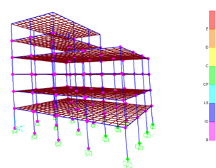
Figure 4. Performance level of plastic hinges for non-strengthened building under earthquake in X-direction
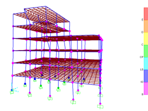
Figure 5. Performance level of plastic hinges for non-strengthened building under earthquake in Y-direction
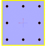
Figure 6. Jacketed column section with CFRP
After some trials, all the plastic hinges developed in the strengthened building satisfied the required Life Safety (LS) performance level. The required columns to be strengthened with CFRP jacketing were 29. The strengthened columns are shown with light blue color in Figure 7. Figures 8 and 9 show the satisfied strengthened building exposed to earthquakes in X- and Y-direction, respectively.
Regarding the TRM strengthening technique, the properties of TRM presented in Table 1 are utilized to represent the section in SAP 2000 software. The TRM jacket was 10 mm thick and had two layers of Carbon Fiber reinforcement.
The thickness per textile is 0.4 mm, and the width is 3.93 mm. The section of the strengthened column using TRM is shown in Figure 10.
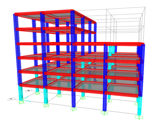
Figure 7. CFRP strengthening scheme
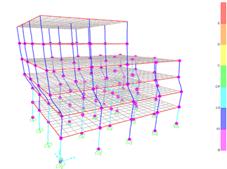
Figure 8. CFRP strengthening scheme with the earthquake in X-direction
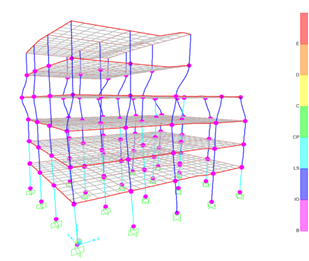
Figure 9. CFRP strengthening scheme with the earthquake in Y-direction
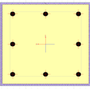
Figure 10. Modeling of TRM jacket (mortar and textile reinforcement) for a column
After some trials, all the plastic hinges developed in the strengthened building satisfied the required Life Safety performance level. The required columns to be strengthened with TRM jacketing were 30. The strengthened columns are shown in green color in Figure 11. Figures 12 and 13 show the satisfied strengthened building exposed to earthquakes in X- and Y-direction, respectively.

Figure 11. TRM strengthening scheme
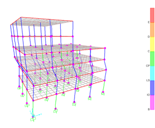
Figure 12. TRM strengthening scheme with earthquake in X-direction
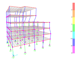
Figure 13. TRM strengthening scheme with earthquake in Y-direction
For the purpose of comparison, the non-strengthened building and strengthened building with CFRP and TRM are plotted together. Figures 14 and 15 illustrate the maximum roof displacement for non-strengthened and strengthened buildings. The strengthened building with the CFRP jacket has a slightly higher value of the maximum displacement (105.03 and 134.35) mm in the X and Y directions, respectively. It is worth noting that the max displacement increased in strengthened buildings with CFRP and TRM jackets with an average ratio of 9% and 4% respectively compared to the original building. From Figures 16 and 17, it can be seen that the displacement values of the first two stories are very close in both strengthened buildings. They are relatively less than those of the non-strengthened building because most of the strengthened columns are at the first two stories. However, the displacement values above the first two stories of the strengthened buildings are higher than those of the non-strengthened buildings. The maximum story drift ratio for all the models, shown in Figures 18 and 19, is at 4.8 seconds in the X and 4.4 seconds in Y- direction for the original and strengthened buildings with the two strengthening techniques. The ground floor is where the largest story drift ratio occurs, and for the two strengthening approaches, this ratio is higher at this level than that of the original building. According to Figures 20 and 21, the base shear of buildings strengthened with CFRP and TRM jackets increases by an average of 8% and 5%, respectively, compared to the non-strengthened building. It is worth noting that the results presented in this study are based on the theoretical simulation of the structure and not on an actual building. In addition, the characteristics of the strengthening technique are selected so that the yield strength is the same for both strengthening techniques. This is conducted by applying these techniques to a single column. However, the behavior of a single column may not be necessarily similar to the behavior of the entire structure.
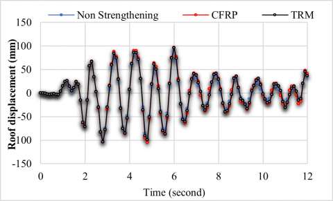
Figure 14. Roof displacement in X-direction
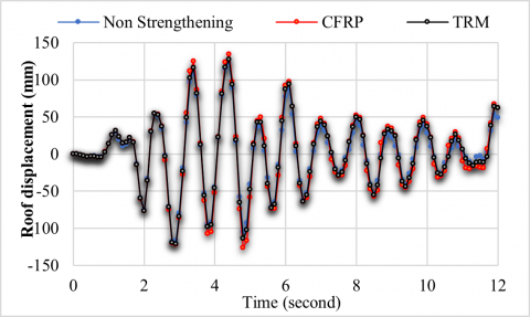
Figure 15. Roof displacement in Y-direction
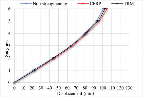
Figure 16. Max story displacement along X-direction

Figure 17. Max story displacement along Y-direction
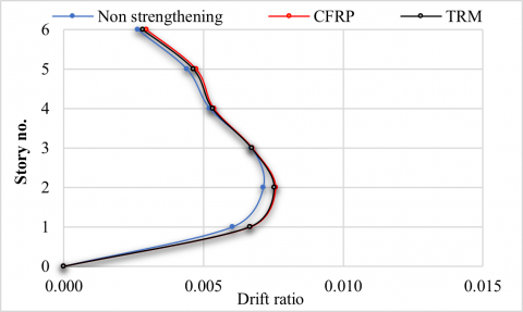
Figure 18. Max story drift ratio along X-direction
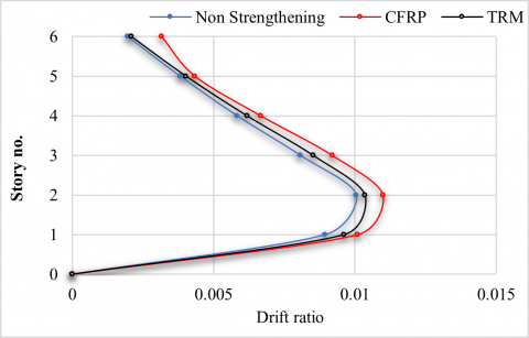
Figure 19. Max story drift ratio along Y-direction
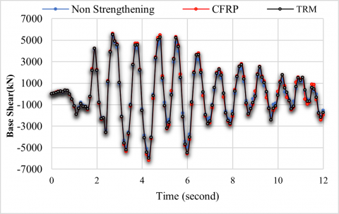
Figure 20. Base shear time history response in X-direction
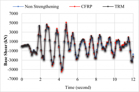
Figure 21. Base shear time history response in Y-direction
To study the cost-effectiveness of the strengthening techniques, the total cost of each technique is estimated. The total cost includes the costs of storing materials, pre-curing, strengthening materials and site cleaning. Tables 2 and 3 summarize the total local costs of the two strengthening techniques; CFRP and TRM, respectively. It was found that the total cost of strengthening a column with CFRP is higher than that with TRM by about 35%. It is important to note that the required number of columns to be strengthened in the building using CFRP and TRM was approximately the same. Therefore, using CFRP to strengthen all failed columns is more expensive than using TRM.
Table 2. Cost of strengthening one column by CFRP
|
No. |
Description |
Units |
Quantity |
Unit Cost ($) |
Total Cost ($) |
|
1 |
Storing materials |
Lump sum |
|
|
60 |
|
2 |
Pre-Curing |
m2 |
6.3 |
30 |
189 |
|
3 |
Adhesive (epoxy) |
m2 |
6.3 |
12 |
76 |
|
4 |
Strengthening material |
m2 |
6.3 |
100 |
630 |
|
5 |
Site cleaning |
Lump sum |
|
|
150 |
|
Total cost of strengthening one column |
1105 |
||||
Table 3. Cost of strengthening one column by TRM
|
No. |
Description |
Units |
Quantity |
Unit Cost ($) |
Total Cost ($) |
|
1 |
Storing material |
Lump sum |
|
|
200 |
|
2 |
Pre-Curing |
m2 |
6.3 |
35 |
221 |
|
3 |
Strengthening material |
m2 |
6.3 |
15 |
95 |
|
4 |
Site cleaning |
Lump sum |
|
|
300 |
|
Total cost of strengthening one column |
816 |
||||
These conclusions are drawn after analyzing RC building before and after strengthening it.
It is evident from the results of the study that the seismic strengthening of an existing structure could be useful in withstanding earthquake loads. Thus, if a building is suspected to undergo future seismic loads, the results of this study could be followed to strengthen the building rather than demolish it.
The present study could be further extended to study horizontally non-symmetrical structures. The characteristics of the strengthening techniques to obtain the same yield strength for them could be selected based on experimental study instead of theoretical study. Further studies will also be needed to be made for different strengthening techniques and different earthquakes.
[1] Realfonzo, R., Prota, A., Manfredi, G., Pecce, M. (2002). Flexural strength of FRP confined RC columns. Proc. 1st fib Congress, October, Osaka, Japan, pp. 41-50.
[2] Youm, K.S., Lee, Y.H., Choi, Y.M., Hwang, Y.K., Kwon, T.G. (2007). Seismic performance of lap-spliced columns with glass FRP. Magazine of Concrete Research, 59(3): 189-198. https://doi.org/10.1680/macr.2007.59.3.189
[3] Pantelides, C.P., Okahashi, Y., Reaveley, L.D. (2008). Seismic rehabilitation of reinforced concrete frame interior beam-column joints with FRP composites. Journal of Composites for Construction, 12(4): 435-445. https://doi.org/10.1061/(ASCE)1090-0268(2008)12:4(435)
[4] Bournas, D.A., Triantafillou, T.C., Zygouris, K., Stavropoulos, F. (2009). Textile-reinforced mortar versus FRP jacketing in seismic retrofitting of RC columns with continuous or lap-spliced deformed bars. Journal of Composites for Construction, 13(5): 360-371. https://doi.org/10.1061/(ASCE)CC.1943-5614.0000028
[5] Ronagh, H.R., Eslami, A. (2013). Flexural retrofitting of RC buildings using GFRP/CFRP–A comparative study. Composites Part B: Engineering, 46: 188-196. https://doi.org/10.1016/j.compositesb.2012.09.072
[6] Ismail, A. (2014). Non linear static analysis of a retrofitted reinforced concrete building. HBRC Journal, 10(1): 100-107. https://doi.org/10.1016/j.hbrcj.2013.07.002
[7] Khlef, K.A., Majeed, F.H., Al-Hussein, A. (2021). Seismic evaluation and strengthening of reinforced concrete buildings. Periodicals of Engineering and Natural Sciences, 10(1): 88-99. http://dx.doi.org/10.21533/pen.v10i1.2587
[8] Sithanandam, K. (2021). Seismic assessment and strengthening of an existing multi-storied RC building – A case study. Politecnico di Milano. https://www.politesi.polimi.it/bitstream/10589/177691/1/2021_07_SITHANANDAM.pdf.
[9] Ahmed, H.A. (2020). Progressive collapse analysis of reinforced concrete buildings subjected to earthquake loads. MSc Thesis, University of Basrah.
[10] Van Den Einde, L., Zhao, L., Seible, F. (2003). Use of FRP composites in civil structural applications. Construction and Building Materials, 17(6-7): 389-403. https://doi.org/10.1016/S0950-0618(03)00040-0
[11] Awani, O., El-Maaddawy, T., Ismail, N. (2017). Fabric-reinforced cementitious matrix: A promising strengthening technique for concrete structures. Construction and Building Materials, 132: 94-111. https://doi.org/10.1016/j.conbuildmat.2016.11.125
[12] ACI 440.2R-02. Guide for the design and construction of externally bonded FRP systems for strengthening concrete structures. ACI Committee 440, American Concrete Institute. Farmington Mills. https://quakewrap.com/frp%20papers/GuideforDesignofExternallyBondedFRP-1.pdf.
[13] D'Antino, T., Papanicolaou, C. (2017). Mechanical characterization of Textile Reinforced inorganic-matrix composites. Composites Part B: Engineering, 127: 78-91. https://doi.org/10.1016/j.compositesb.2017.02.034
[14] Kalibhat, M.G., Kumar, A.Y., Kamath, K., Prasad, S.K., Shetty, S. (2014). Seismic performance of RC frames with vertical stiffness irregularity from pushover analysis. IOSR Journal of Mechanical and Civil Engineering, 2: 61-66.