Maher Ali Hussein*![]() | Abbas Allawi Abbas
| Abbas Allawi Abbas![]() | Mohand Mosa Mohammad
| Mohand Mosa Mohammad![]()
© 2023 IIETA. This article is published by IIETA and is licensed under the CC BY 4.0 license (http://creativecommons.org/licenses/by/4.0/).
OPEN ACCESS
Sheet metal is widely used in industry and in different production processes. The present work aims to reduce the bending force in the air-die bending process. Different mild steel sheet thicknesses (0.5, 0.75, 1, and 1.25 mm) were considered, and two techniques were proposed. The first technique involves an annealing process, while the second one considers cutting a rectangular hole along the bending line. The bending stress was calculated using Autodesk inventor software. The results revealed that the annealing process can provide significant ductility improvement and hence bending force reduction, and that annealing time is an important factor that influences ductility development. Moreover, cutting a hole along the bending line could reduce the bending stress and consequently the bending force. The study also reported that increasing the thickness beyond a specific value could result in a reduction in bending force instead of an increase, which is attributed to a temperature increase in the sheet and bending tool.
sheet metal, air bending die, annealing process, bending force
Sheet metal bending is a very common process in engineering applications; however, it has several practical issues, such as the need for a high load and the spring-back effect. Several studies have considered these issues in low-carbon steel sheet metal with different thicknesses and other parameters considered in the study included the addition of a die angle, a die width, and a punch diameter for a V-bending die.
The sheet metal has kinematic bending will allow to manufacture parts with high elasticity which concerning the geometry Hoffmann et al. [1] and Singh [2]. The applied axis force on sheet metal to produce asymmetric cross section which used kinematic bending process to resist spring back and warping. The partial heating of cross section to reduce geometric deflection which lead to reduce flow stress locally.
Farsi and Arezoo [3] developed an equation to predict the bending force required in a V-bending die. Kabir et al. [4] investigated the aluminum-glass fiber sandwich panel to evaluate its behavior in bending and to enhance the mechanical properties of the light-weight composites. Besides, Leu [5] conducted a set of tests on an air-bending die. The tests comprised stress-strain, stress-displacement, load-displacement, stress-time, strain-time, load-time, and displacement-time by using AIMIL-UTM. The study concluded that the sandwich panel (aluminum composite material) has better mechanical properties than monolithic aluminum.
Radius of the die and punch is an influencing parameter in the sheet steel V bending die. It has been considered comprehensively in many studies in recent years. Leu [5] and Guo and Tang [6] presented an experimental investigation that involved observation of the spring back behavior when different diameter dies and punches were used. The experimental design used the full factorial and analysis of variance methods to specify the radius effect and predict the spring back behavior. At level 0.05, the statistical analysis revealed that die and punch radiuses were a significant factor in limiting the spring-back effect. Also, the results showed that to reduce the spring-back effect, the die and punch diameters must be reduced. Anudeep and Ramesha [7] and Rachik et al. [8] discussed the design and the analysis procedure to develop a bending press tool for anchor bracket component production. Press tool manufacturing is an emerging trend in production lines, especially in the aircraft and automobile industries, due to the high dimensional accuracy of the produced components. The anchor bracket is a part of automobiles’ brake assemblies; the operation sequence was initially deliberated before the design and analysis of the press tool were performed. The purpose of conducting the analysis is to avoid expensive trials and optimize production rate and quality.
Due to the significant impact of the spring-back phenomenon in sheet metal forming processes, Chikalthankar et al. [9] presented a review that considered a wide range of influencing parameters that affect the spring-back behavior. The investigated parameters included the punch angle and radius, sheet thickness and die radius to sheet thickness ratio, sheet grain direction, punch height, die opening, coining force, etc. According to Chikalthankar et al. [9] and Kazan et al. [10], the reason behind the spring-back effect is the internal stress redistribution posterior to the release of deforming stress. It is very important to use techniques for spring-back effect compensation if you want the geometry of sheet metal parts to be exact. Rady et al. [11] and Hussein et al. [12] discussed the effect of heat treatment on improving tensile strength and hardness.
In this study, two approaches have been proposed to reduce the bending force required for mild steel sheet bending in the air die bending process. In the first approach, an annealing process with different annealing times was proposed to reduce the steel's UTS and improve its ductility. The second way to reduce the bending stress is to cut a square hole along the line where the sheet bends.
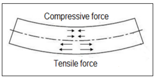
The sheet metal bending process involves metal straining relative to a straight line. The internal part of the metal is subjected to compression while the external part undergoes stretching, as shown in Figure 1. There are three different types of bending die in metal forming process: air die bending, V die bending, and wipe die bending. The air die bending, which is used in the current study only, is a flexible die where the bending angle changes while the punch travels until the sheet metal angle becomes the same as that of the punch, as illustrated in Figure 2 [13-16].
Figure 1. Straining of sheet metal during bending
Figure 2. Air bending process
The process of air bending begins with the maximum bending force (Fmax), as shown in Eq. (1), and gradually decreases throughout the process [17, 18].
$F \max =\frac{K[(U T S) . L s .(T s) 2]}{W d}$ (1)
where, K is a constant, UTS is the Ultimate Tensile Strength, Ls is length of bending line, T is the metal sheet thickness, and Wd is the width of air bending die.
The bending stress, based on the maximum bending forces, required to perform sheet metal bending for different mild steel sheet thickness (0.5, 0.75, 1, 1.25 mm) is calculated using Eq. (2).
Stress bending $=\frac{M \cdot C}{I}$ (2)
Here, M is the bending moment in (N. m), C is the translate stress distance from min. to max. which depend on cross section of sheet metal, and I is the moment of inertia also depend on cross section of sheet metal, therefore the unit of max. Bending stress is (Mpa).
The previous studies specified that the auto desk inventor software is effective in simulating the sheet metal bending process and can be used to reproduce the theoretical results given in the above equations. Therefore, it will be employed in the current study.
3.1 Specimens preparation
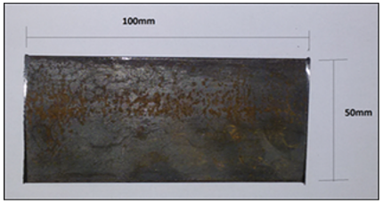
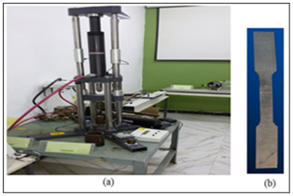
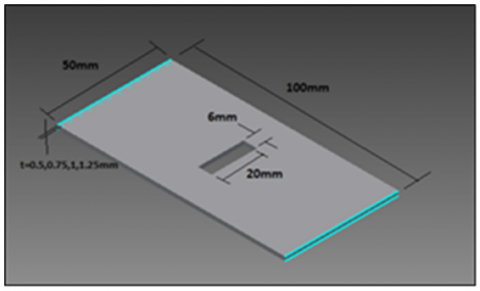
In the current study, mild steel sheets with different thicknesses (0.5, 0.75, 1, and 1.25 mm) were used to prepare the test specimens; the chemical composition of the sheets is given in Table 1 below. Eight specimens with dimensions of 100 mm 50 mm (L×W) and different thicknesses were cut out of the steel sheet, as shown in Figure 3. Four of them were subjected to the annealing process while rectangular holes were cut along the bending lines of the other four specimens. Figure 4 displays the tensile test equipment employed in the current study as well as the test sample of sheet metal tensile.
Table 1. The chemical components of sheet mild steel
|
Fe% |
P% |
Mn% |
Si% |
C% |
|
98.7 |
0.16 |
0.54 |
0.2 |
0.17 |
Figure 3. Mild steel specimen used in the experimental work
Figure 4. (a) The tensile test equipment; and (b) Sheet metal tensile test sample
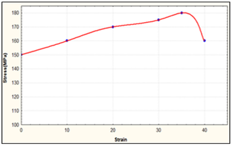
A tensile test was firstly performed to evaluate the mild steel stress-strain relation; the result of the test is shown in Figure 5 below. The tensile equipment and sample are shown in Figure 4. Then, the specimens were divided into two groups: in the first group, specimens were subjected to an annealing process for different intervals to reduce the ultimate tensile strength (UTS) and improve the ductility. In the second group, a rectangular hole was cut in the middle of the bending line to reduce the specimens’ bending line length.
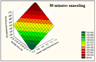
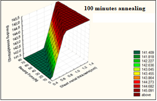
The annealing process was performed by heating the specimens in a furnace at 723℃ for two different periods (80 minutes and 100 minutes), before they were cooled to enhance the ductility and tensile strength. The mild steel construction has a carbon ratio less than 77% or above eutectoid between 723 and 1,100℃ for the interval time (80 to 100 minutes) and then cooling in the furnace to obtain steel with high ductility and suitable tensile stress. A tensile test was performed for each annealing period; the results revealed that the strengths were 168 MN/m2 and 145 MN/m2 for 80 minutes and 100 minutes, respectively. The results presented in Figure 6 show the required bending force for different sheet thicknesses. Figure 7 show the relation between the bending stress and the sheet thickness at 80 and 100 minutes annealing periods, respectively.
Figure 5. Tensile test result for mild steel sheet specimens
Figure 6. Simulation of (0.5, 0.75, 1, 1.25mm) sheet mild steel thickness under bending load of air bending die
(a)
(b)
Figure 7. Bending stress and force for different steel sheet thickness, (a) after 80 minutes annealing; (b) after 100 minutes annealing
The other technique for reducing the required bending force is by reducing the length of the bending load line (Ls), as shown in Figure 8. According to Eq. (1), this may result in a reduction in the reaction stress subjected to a bending punch, which is due to the reduced area that is subjected to the bending.
Figure 8. Mild steel sheet which is cut rectangular hole in middle of bending load
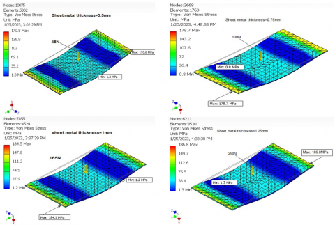
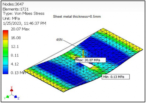
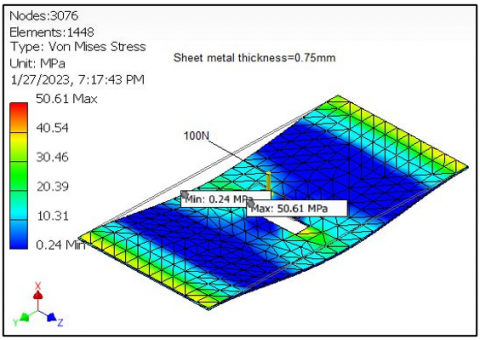
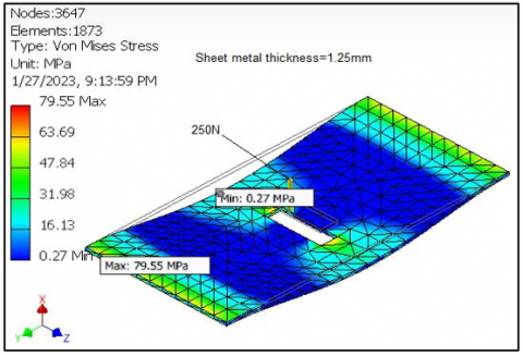
The subjected bending force in Figures 9, 10, 11, and 12 has the same value as the bending force in Figure 6.
Figure 9. Bending load 45N on sheet with rectangular hole on bending load
Figure 10. Bending load 100N on sheet with rectangular hole on bending load
Figure 11. Bending load 170N on sheet with rectangular hole on bending load
Figure 12. Bending load 260N on sheet with rectangular hole on bending load
Eq. (1) says that the amount of force needed to bend a sheet is proportional to the material's ultimate strength, the length of the bending line, and the square of the sheet's thickness. On the other hand, it is inversely proportional to the width of the die aperture. All these parameters were measured experimentally and implemented in Eq. (1), and the following outcomes were determined: It was found that as the sheet thickness increases, the required bending force and the spring back effect on the bending tool increase, as shown in Figure 13.
Figure 13. The effect of metal thickness on the forces and stresses bending
Table 2. The results of producing stress in every case
|
Thickness mm |
$\sigma$ bending simulation without any treatment (MPa) |
$\sigma$ bending in annealing at 80min. (MPa) |
$\sigma$ bending in annealing at 100min. (MPa) |
$\sigma$ bending simulation with rectangular hole (MPa) |
|
0.5 |
170 |
155 |
141 |
20 |
|
0.75 |
178.2 |
156 |
142 |
50.6 |
|
1 |
184.5 |
158 |
143 |
68.16 |
|
1.25 |
186.8 |
161 |
143.5 |
79.55 |
The results revealed that at 0.75 mm sheet thickness, the developed stress was 180.6 MPa, which represents the maximum stress. Further, at 0.5 mm thickness, the stress was 176 MPa, which signifies the minimum developed stress. However, at higher thickness (1.25 mm), the stress was 179.8 MPa, which is below the maximum stress. This is attributed to the increase in bending tool temperature during the punch's movement along its path from point to point. This helps reduce the stress required for the bending process.
Besides, Figures 6 shows the results of the stress analysis for the bending process using the force calculated in Eq. (1). The results show that the maximum stresses were at 1 mm and 1.25 mm thickness, this confirms the above-mentioned observation with an 85% correlation factor.
The annealing process is usually used to improve the ductility of mild steel before conducting the forming process. It is done in a furnace where the steel is heated to a certain temperature for a certain amount of time. This lowers the UTS and makes the steel easier to bend.
Figures 7 illustrate the required bending force and the produce stress when the steel sheets are annealed for 80 min and 100 min respectively. For 80 min, the required bending force was 39-240N, and for 100 min the required force was 24-225N. This indicates that the annealing process and the annealing time have significant role in reducing the bending force and the stress subjected of the sheet and the bending tool.
Figure 8 shows the mild steel sheet with a rectangular hole in the middle of the bending force line. The sheet was subjected to the same bending force given in Figure 9, Figure 10, Figure 11, and Figure 12. The results show a significant reduction in maximum stress in the bending area to 20, 50.6, 68.16, and 79.55 MPa for sheet thicknesses of 0.5, 0.75, 1, and 1.25mm, respectively. This indicates that cutting a hole along the bending line may reduce the bending stress by up to 80%. The technique is applicable when the cut hole doesn't affect the final sheet's performance and utilization. The results Can be listed in Table 2, The table shows the producing stresses for every case and the annealing effect is low for comparison with normal case, and when the heating increased then the producing stress is low, while in sheet metals have rectangular hole will get good results, where the producing stress is low in sheet metal and in inverse direction bending tool.
Due to the variety of engineering industries and production processes that use sheet metal bending, this study was proposed to investigate the potentiality of reducing the bending force required to bend mild steel sheet in an air die bending process. Different steel sheet thicknesses (0.5, 0.75, 1, and 1.25 mm) were considered in the study, and two techniques were adopted to minimize the bending force. The first is by using the annealing process, and the second is by cutting a rectangular hole along the bending line. The study has concluded with some interesting findings.
Normally, increasing the thickness of the steel sheet increases the bending force; however, this is only true up to a certain point. Increasing the sheet thickness beyond this limit was found to reduce the required bending force, and this was attributed to the increase in temperature while the punch travels in its stroke in the bending process. The auto desk inventor software has been shown to produce acceptable results that correlate well with experimental data. Accordingly, the use of this software has been verified as a powerful technique in the production process. According to Eq. (1), the annealing process proved to provide a good reduction in bending force due to the reduction in the ultimate tensile stress and the ductility improvement.
Moreover, the annealing time was reported to be an important factor that influences ductility development. Another technique to reduce the bending stress is to cut a rectangular or elliptical hole along the bending line. The hole contributes to reducing the required bending force; however, this method is controlled by the end product's design and utilization.
|
UTS |
Ultimate Tensile Strength (Mpa) |
|
Ls |
Length of bending line (mm) |
|
T Wd |
The metal sheet thickness (mm) Width of air bending die (mm) |
|
M |
Bending moment (N.M) |
|
C |
The translate stress distance from min. to max |
|
I |
Moment of inertia (Kg.m2) |
|
Greek symbols |
|
|
$\sigma$ |
Bending Stress (Mpa) |
[1] Hoffmann, E., Meya, R., Tekkaya, A.E. (2021). Reduction of warping in kinematic l-profile bending using local heating. Metals, 11(7): 1146. https://doi.org/10.3390/met11071146
[2] Singh, D.K. (2021). Strength of Materials. 4th ed. Springer International Publishing: New York, NY, USA.
[3] Farsi, M.A., Arezoo, B. (2011). Bending force and spring-back in v-die-bending of perforated sheet-metal components. Journal of the Brazilian Society of Mechanical Sciences and Engineering, 33(1): 45-51. https://doi.org/10.1590/S1678-58782011000100007
[4] Kabir, K., Vodenitcharova, T., Hoffman, M. (2014). Response of aluminium foam-cored sandwich panels to bending load. Composites Part B: Engineering, 64: 24-32. https://doi.org/10.1016/j.compositesb.2014.04.003
[5] Leu, D.K. (2015). Position deviation and springback in V-die bending process with asymmetric dies. The International Journal of Advanced Manufacturing Technology, 79: 1095-1108. https://doi.org/10.1007/s00170-014-6532-x
[6] Guo, Z., Tang, W. (2017). Bending angle prediction model based on BPNN-spline in air bending springback process. Mathematical Problems in Engineering, 2017: 7834621. http://dx.doi.org/10.1155/2017/7834621
[7] Anudeep, S., Ramesha, N. (2015). Design and analysis of blanking and bending press tool to produce anchor bracket component. International Journal of Engineering Research & Technology (IJERT), 4: 1035-1039.
[8] Rachik, M., Roelandt, J.M., Maillard, A. (2002). Some phenomenological and computational aspects of sheet metal blanking simulation. Journal of Materials Processing Technology, 128(1-3): 256-265. https://doi.org/10.1016/S0924-0136(02)00460-0
[9] Chikalthankar, S.B., Belurkar, G.D., Nandedkar, V.M. (2014). Factors affecting on springback in sheet metal bending: A review. International Journal of Engineering and Advanced Technology, 3(4): 247-251.
[10] Kazan, R., Fırat, M., Tiryaki, A.E. (2009). Prediction of springback in wipe-bending process of sheet metal using neural network. Materials & Design, 30(2): 418-423. https://doi.org/10.1016/j.matdes.2008.05.033
[11] Rady, M.H., Mustapa, M. S., Wagiman, A., Al-Alimi, S., Shamsudin, S., Lajis, M.A., Harimon, M.A. (2020). Effect of the heat treatment on mechanical and physical properties of direct recycled aluminium alloy (AA6061). International Journal of Integrated Engineering, 12(3): 82-89.
[12] Hussein, M.A., Abbas, A.A., Abdul-Nabe, R.A. (2018). Enhancement the mechanical properties of the deep drawing products through intelligence design and finite element analysis. Jour of Adv Research in Dynamical & Control Systems, 10(13): 2156-2169.
[13] Hussein, M.A., Abbas, A.A., Muslim, N.H. (2022). Experimental and numerical study of different methods' effects on lubricant flow on temperatures and strains of turning cutting tool (HSS). Instrumentation Mesure Métrologie, 21(4): 133-138. https://doi.org/10.18280/i2m.210402
[14] Ikumapayi, O.M., Akinlabi, E.T., Madushele, N., Fatoba, S.O. (2020). A brief overview of bending operation in sheet metal forming. In: Emamian, S.S., Awang, M., Yusof, F. (eds) Advances in Manufacturing Engineering. Lecture Notes in Mechanical Engineering. Springer, Singapore. https://doi.org/10.1007/978-981-15-5753-8_14
[15] Hattalli, V.L., Srivatsa, S.R. (2018). Sheet metal forming processes–recent technological advances. Materials Today: Proceedings, 5(1): 2564-2574. https://doi.org/10.1016/j.matpr.2017.11.040
[16] Abdair, D.A., Abbas, A.M., Hussain, H.K. (2022). Punching shear behavior of flat slab strengthen with Y-type perfobond shear. Mathematical Modelling of Engineering Problems, 9(4): 1095-1106. https://doi.org/10.18280/mmep.090428
[17] Shi, X., Zhang, J., Xiao, Q., Liu, T. (2016). Crack initiation and early propagation plane orientation of 2A12-T4 aluminum alloy under tension-torsion fatigue loading including mean tensile stress. Frattura ed Integrità Strutturale, 10(35): 441-448. https://doi.org/10.3221/IGF-ESIS.35.50
[18] Trzepiecinski, T., Lemu, H.G. (2017). Prediction of springback in V-die air bending process by using finite element method. In MATEC Web of Conferences, 121: 03023. https://doi.org/10.1051/matecconf/201712103023