Ali Samir![]() | Karrar A. Hammoodi*
| Karrar A. Hammoodi*![]() | Ihab Omar
| Ihab Omar![]() | Ali Basem
| Ali Basem![]() | Mujtaba A. Flayyih
| Mujtaba A. Flayyih
© 2023 IIETA. This article is published by IIETA and is licensed under the CC BY 4.0 license (http://creativecommons.org/licenses/by/4.0/).
OPEN ACCESS
The hybrid combustor is represented by combined between premixed and diffusion flame. The premixed flame implemented by cylindrical burner which it gives swirling flow by two nozzles in opposite direction. The diffusion flame investigated by co-axial jet of fuel and annulled by air. The hybrid flame was experimentally and numerically investigated to get high level of flame stability and low emissions level of pollutant. This research used working fuel of liquid petroleum gas which it has 40% propane and 60% butane. Two types of flame were examined, diffusion flame combustion DFC and hybrid flame combustion HFC. In HFC, the influences of fuel nozzle geometry on air/fuel mixing were achieved in terms of stability of flame and level of pollutant emissions. An extremely stability of flame can be given in HFC by the swirling premixed which utilized it as a flame holder because it created over all inner surface of burner. The results showed that the burner design gave high vortex flow by evaluating swirl number for hybrid flame in term of heat input and overall equivalent ratio. The results of flame temperature for three types of combustion premixed flame combustion PFC, DFC and HFC with lean, rich and stoichiometric of equivalence ratio. Numerically studded temperature distribution of diffusion flame combustion by simulate cyclone burner which using in experimental work. Fluent Ansys 16.1 used for 2D simulate turbulent modeling (Standard k-ε model). Three cases of mixture investigated numerically lean, rich and stoichiometric and compared it with experimental rustles. The temperature observed numerically is more than which observed experimentally because the enhancement in heat transfer through test rig burner and low mixing efficiency between air and fuel.
hybrid burner, flame temperature, stability of flam
The diffusion and Premixed combustion types classified according to the provide way of air and fuel inside the burner, have collision advantages in terms of emissions of pollutant and stability of flame. The advantage of diffusion flame is higher stability, while the second type (premixed flame) is minimum emissions its means clean combustion as compared with another types. Due to the flame stability in practical combustor represents significant industrial design factor. Recently, to meet the increasingly emission controls, The recently toward to the premixed combustion so its application has been gradually enhancement with numerous advantages like shorter flame length burner, higher thermal efficiency, likewise low emissions level as compared with the type of diffusion flame [1]. Even so, the stability of flame (flash-back and lifting-limits) is limited in the premixed combustion type. There are many strategies to enhance the stability of the premixed flame by creating swirl flow, cyclone configuration and pilot flames. The cyclone configuration grants a flow in a swirl shape due to air/fuel ratio tangential at inlet consequently develops the mixing of air-fuel and the stability level of flame by increasing chemical species recirculation [2, 3]. Otherwise, the combustor of cyclone configuration has a simpler burner design and the intensity of swirl is high as compared to a traditional swirl burner (complicated swirl design) [4, 5]. Ishizuka et al. [6] and Shimokuri et al. [7] investigated the premixed flame type in tube experimentally which was created by using tangentially slots through the tube.
They discovered thermally stable of tubular flame due to the structure symmetrically of chemical surroundings, and the aerodynamically stable due to suitable heat relief and pressure distributions for break the instabilities of combustion. Even so, slit width or slit length for tubular combustion type are additional improvements to complete gases burn at high velocities (50 meter/sec) because the little combustion residence time. Onuma et al. [8] improved a cyclone configuration burner to meet the high level of stability of premixed& diffusion flame and minimum pollution. The fuel of premixed flame provided into tangentially slots of the burner to utilize that technique to holder of flame which its work to stabilize the type of diffusion flame. The emission could be closely degreased of non-diffusion combustion by enhance the mixing rate. The hybrid flame combustion type using the premixed and diffusion combustion types together, its supply the two benefits in terms of pollutant emissions and stability of flame. Hwang et al. [9] and Noda et al. [10] achieved experimentally the high level of flame stability and low pollutant emissions at the cyclone hybrid burner. By means of developing the configuration design of the fuel injection for the diffusion flame, it noted that an enhancement in mixing rate of reactions by using a multi slots fuel injection to grants a stability of flame approximately double as wide as that of the fuel injection when using a single slot. Also, an optimized burner investigating by hybrid flame combustion type yielded NOx combustor for clean burning and effective [11].
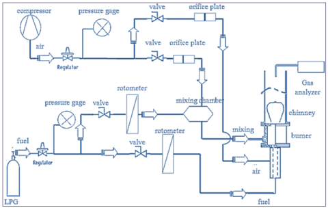
Figure 1 shows the schematic diagram of the experimental test rig.
Figure 1. Schematic diagram of the experimental apparatus
The burner is designed and implemented from:
a. Cylindrical combustion chamber constricted from stainless steel with inner diameter of (40 mm), thickness (2 mm) and length (35 mm). The combustion chamber is provided with upper opening (25 mm) diameter and lower opening (20 mm) diameter.
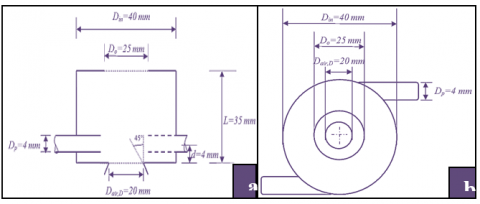
b. Air – fuel mixture supplier: The combustion chamber is connected tangentially to welding two slots (4 mm) diameter, placed at (4 mm) distance from the bottom of combustion chamber to provide fuel/air mixture for premixed combustion in a way to achieve swirl flow of mixture. Figures 2 shows the schematic diagram of the cylindrical combustion chamber.
Figure 2. Schematic diagram of the experimental apparatus: (a) Front view; (b) Top view
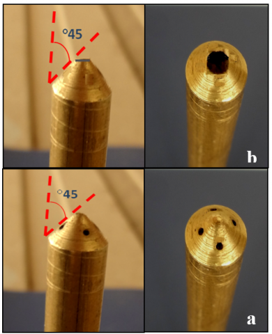
c. Annular diffusion flow: The bottom opening of the combustion chamber is connected with a pipe (60 mm) length and (20 mm) diameter at ended pipe inclined at 45° inward for air supply, with a central pipe of inner diameter (4 mm) for fuel supply. The central pipe is ended with two types of nozzles. Nozzle (1): Axial fuel nozzle with (4 mm) diameter and (70 mm) length, designed with a conical end which inclined at 45° inward with four holes that uniformly distributed at ended position, Figure 3 (a) shows the manufacturing photograph of fuel nozzle (1). Nozzle (2): Axial fuel nozzle with (4 mm) diameter and (70 mm) length, designed with a single hole by cone half section ended nozzle which inclined by 45° inward, Figure 3 (b) shows the manufacturing photograph of fuel nozzle (2).
Figure 3. Photograph of the fuel nozzle: (a) Nozzle 1; (b) Nozzle 2
The details of manufacturing dimensions for both nozzle (1) and (2) as shown in Table 1.
Table 1. Conditions of axial fuel and air nozzles
|
Nozzles |
Fuel Nozzle |
Air Nozzle |
|||
|
No. hole |
Din (mm) |
Area (mm2) |
Din (mm) |
Area (mm2) |
|
|
Nozzle (1) |
4 |
1 |
3.14 |
20 |
314.1 |
|
Nozzle (2) |
1 |
2 |
3.14 |
20 |
314.1 |
Figure 4. Schematic diagram of thermocouple position to measuring flame temperature
2.1 Temperature measurement
Thermocouple type (S) (porcelain) with a temperature (0-1,400℃) was used to measure the flame temperature. The thermocouple was connected with a digital thermometer for measuring the temperature. Figure 4 depicts the photographs for the flame and burner with holes for flame temperature measurement by thermocouple.
2.2 Swirl number (SN)
The swirl number represents the of the flux of angular momentum divided by the flux of axial momentum, for cyclone burner (Hwang et al. [9]).
$\mathrm{SN}=\frac{2 \pi \rho \int_0^R U_x U_\theta r^2 d r}{2 \pi \rho R_{i n} \int_0^R U_x^2 r d r}$
where, $\rho:$ Density of air and fuel mixture.
R: Inner raduis of cyclon combustor.
r: Raduis of annular air nozzle.
3.1 Mathematical Concept
A modeling of mathematical turbulent flow is achieved by using partial differential equations (PDE) to the derivative of nonlinear equation which represent mass, chemical species, and momentum conservation and energy equations for 2D burner in surrounding [12].
The conservation of mass equation in form of:
$\frac{\partial \rho}{\partial t}+\frac{\partial}{\partial x_j}\left(\rho V_j\right)=0$ (1)
where, ρ: Density, Vj: The instantaneous velocity at different direction of j, where (j = 1, 2, 3).
The averaged momentum equation is given as follows:
$\begin{aligned} & \frac{\partial}{\partial t}\left(\rho V_j\right)+\frac{\partial}{\partial x_j}\left(\rho V_i V_{\mathrm{j}}\right)=-\frac{\partial \mathrm{p}}{\partial \mathrm{x}_{\mathrm{j}}}+\frac{\partial \tau_{\mathrm{ij}}}{\partial \mathrm{x}_{\mathrm{j}}}+\frac{\partial}{\partial \mathrm{x}_{\mathrm{j}}}\left(-\rho \bar {\grave{V}_{\mathrm{i}} \grave{V}_{\mathrm{j}}}\right) +F_j & \end{aligned}$ (2)
where, τi: Stress tensor which written as follow:
$\tau_{i j}=\mu\left[\left(\frac{\partial \mathrm{V}_{\mathrm{i}}}{\partial \mathrm{x}_{\mathrm{j}}}+\frac{\partial \mathrm{V}_{\mathrm{j}}}{\partial \mathrm{x}_{\mathrm{j}}}\right)-\frac{2}{3} \delta_{\mathrm{ij}}\left(\frac{\partial \mathrm{V}_{\mathrm{k}}}{\partial \mathrm{x}_{\mathrm{k}}}\right)\right]$ (3)
And, -ρVi’ Vj’: Reynolds stresses which expressed by: where, P: Pressure, µ: Fluid dynamic viscosity, µt: Turbulent viscosity.
The energy equation is given by:
$-\rho \overline{\grave{V}_{\mathrm{i}} \grave{V}_{\mathrm{j}}}=\mu_{\mathrm{t}}\left(\frac{\partial \mathrm{V}_{\mathrm{i}}}{\partial \mathrm{x}_{\mathrm{j}}^{\mathrm{}}}+\frac{\partial V_{\mathrm{j}}}{\partial \mathrm{x}_{\mathrm{j}}}\right)-\frac{2}{3} \delta_{\mathrm{ij}}\left(\rho_{\mathrm{k}}+\mu_{\mathrm{t}} \frac{\partial \mathrm{V}_{\mathrm{j}}}{\partial \mathrm{x}_{\mathrm{j}}}\right)$ (4)
$\frac{\partial(\rho h)}{\partial t}+\frac{\partial}{\partial \mathrm{x}_{\mathrm{j}}}\left(\rho \mathrm{V}_{\mathrm{j}} \mathrm{h}\right)=\frac{\partial}{\partial \mathrm{x}_{\mathrm{j}}}\left(\rho \mathrm{D}_{\mathrm{h}}\right) \frac{\partial \mathrm{h}}{\partial \mathrm{x}_{\mathrm{j}}}-\rho \overline{{\grave{h}} \grave{V}_{\mathrm{j}}}$ (5)
where, Dh=λ/ρcp: Thermal diffusivity, -ρh’ Vj’: Correlation term between the enthalpy(h) and fluctuation of velocity.
Mass enthalpy hk for each species written as follow:
$\mathrm{h}=\sum_{\mathrm{k}=1}^{\mathrm{n}} \mathrm{Y}_{\mathrm{k}} \mathrm{h}_{\mathrm{k}}$ (6)
Chemical species conservation equation for reactive mixture is given by:
$\frac{\partial\left(\rho Y_k\right)}{\partial t}+\frac{\partial\left(\rho V_{\mathrm{i}} Y_k\right)}{\partial {x}_j}=\frac{\partial J_{\mathrm{j}}^{\mathrm{k}}}{\partial {x}_{\mathrm{j}}}+\rho \grave{\mathrm{w}}_{\mathrm{k}}$ (7)
where, Yk, wk, Jjk are mass fraction, k: Species of the production rate & mass diffusion flux in direction of j. The chemical equation of combustion liquid petroleum gas LPG (40% propane, 60% butane) has been given by:
$\begin{gathered}0.4 \mathbf{C}_3 \mathbf{H}_8+0.6 \mathbf{C}_4 \mathbf{H}_{10}+5.9\left(\mathbf{O}_2+3.76 \mathbf{N}_2\right) \\ 3.6 \mathbf{C O}_2+4.6 \mathbf{H}_2 \mathbf{O}+22.184 \mathbf{N}_{\mathbf{2}}\end{gathered}$ (8)
3.2 Modeling of turbulence
In turbulent the Reynolds revealed new unknown term which it’s part of Navier-Stokes equations (the non-linearity). -ρVi’ Vj’ represents correlation between directions i & j and fluctuations speeds, -ρh’ Vj’ represents correlation between the mass enthalp and fluctuations speeds. The standard k-ε model is interested in this study.
The standard k-ε turbulence model: The k-ε standard turbulence model is consist of 2 equations, the first one is the kinetic energy of turbulent and the second one grants the characteristic of scale length of the turbulent. The kinetic energy of turbulent k & the kinetic energy of turbulent of the dissipation rate ε are given as follows:
$\frac{\partial(\rho \mathrm{k})}{\partial \mathrm{t}}+\frac{\partial\left(\rho \mathrm{V}_{\mathrm{i}} \mathrm{k}\right)}{\partial \mathrm{x}_{\mathrm{j}}}=\frac{\partial}{\partial \mathrm{x}_{\mathrm{j}}}\left[\left(\mu+\frac{\mu_{\mathrm{t}}}{\sigma_{\mathrm{k}}}\right) \frac{\partial \mathrm{k}}{\partial \mathrm{x}_{\mathrm{j}}}\right]+\mathrm{P}_{\mathrm{k}}-\rho \varepsilon$ (9)
$\begin{gathered}\frac{\partial(\rho \varepsilon)}{\partial \mathrm{t}}+\frac{\partial\left(\rho \mathrm{V}_{\mathrm{j}} \varepsilon\right)}{\partial \mathrm{x}_{\mathrm{j}}}=\frac{\partial}{\partial \mathrm{x}_{\mathrm{j}}}\left[\left(\mu+\frac{\mu_{\mathrm{t}}}{\sigma_{\mathrm{k}}}\right) \frac{\partial \varepsilon}{\partial \mathrm{x}_{\mathrm{j}}}\right] \\ +\mathrm{C}_{\varepsilon 1} \frac{\varepsilon}{\mathrm{k}} \mathrm{P}_{\mathrm{k}}-\mathrm{C}_{\varepsilon 2} \rho \frac{\varepsilon^2}{\mathrm{k}}\end{gathered}$ (10)
where, the term of turbulent viscosity & the term of turbulent kinetic energy are defined by:
$\mathrm{P}_{\varepsilon}=\mathrm{C}_{\varepsilon 1} \frac{\varepsilon}{\mathrm{k}} \mathrm{P}_{\mathrm{k}}$ (11)
$\mu_{\mathrm{t}}=\rho \mathrm{C}_\mu \frac{\mathrm{k}^2}{\varepsilon}$ (12)
3.3 Combustion modeling
The turbulent no-premixed flame is interested in this study. Thus, the model of Eddy Dissipation was chosen to seeking the rate of reactions and observation the turbulence interaction. This model has showed for turbulent diffusion flames at fast reactions infinitely. The origin expression of production of species i because the reaction is presented the lower of mixing rate of product & mixing rate of the reactant:
$\mathrm{S}_{\mathrm{mf}}=-\rho \frac{\varepsilon}{\mathrm{k}} \min \left\lceil\grave{\mathrm{u}}_{\mathrm{i}} \mathrm{M}_{\mathrm{w}, \mathrm{i}} \mathrm{A}\left(\frac{\mathrm{Y}_{\mathrm{R}}}{\grave{u}_{\mathrm{R}} \mathrm{M}_{\mathrm{w}, \mathrm{R}}}\right), \grave{\mathrm{u}}_{\mathrm{i}} \mathrm{M}_{\mathrm{w}, \mathrm{i}} \mathrm{AB} \frac{\sum_{\mathrm{P}} \mathrm{Y}_{\mathrm{P}}}{\sum_{\mathrm{j}}^{\mathrm{N}} \grave{\mathrm{u}}_{\mathrm{j}} \mathrm{M}_{\mathrm{w}, \mathrm{j}}}\right\rceil$ (13)
3.4 Procedure of discretization
The commercial CFD code ANSYS Fluent 16.1 used in this study, model the combustion in no-premixed flame [(40%propane+60%butane)-air] with a cyclone burner. The governing equations of numerical solution which including mass equation, momentum equation, energy equation, and species of (reaction and products) investigated by a finite volume method. The pressure and velocity coupling algorithm as a simple formula as well as the upwind scheme of discretization are applied to resolve the governing equations. The Eddy dissipation model applied to consider the reactions turbulent.
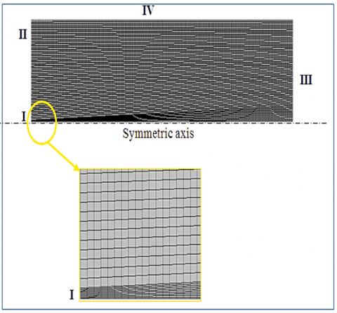
3.5 Boundary conditions and meshing
The experimental test rig was implemented and studied premixed, diffusion and hybrid flame burner. The comparison of three types of flame in experimental work was investigated. The diffusion flame burner was numerically achieved by cyclone burner which its configuration is axis-symmetric. The of cylindrical coordinates of (computational fluid dynamics) CFD Ansys Fluent 16.1. This paper is concerned to make comparison the numerical results of diffusion flame with experimental result. A rough grid of numerical results had a big different from the experimental datum. Actually, the mathematical results are closing to the experimental works with the grid gradual refining. Thus, the using of no-uniform grid spacing grants a precise resolution near to the central of the cyclone burner. For the full domain simulation, a control volume is divided into uninform quadrilateral in order to resolve the steep gradients and to conserve flux in each cell. A total number of 34,500 cells with 3,590 nodes were used for the simple cylindrical injector as shown in Table 2 of grid parameter for half symmetric burner. The design of the geometry of the volume control and the mesh generation was performed using the software "GAMBIT" with a quadratic mesh. A refined mesh in the area near the exit of the burner is represented to fully model the differences phenomena. The other order which inverses scheme used the convective terms of momentum equations, the turbulent kinetic energy and the dissipation rate of the turbulent kinetic energy. For speed correction pressure the simple algorithm is used.
From experimental test rig configuration, the boundary conditions are determined as shown in Figure 5. The inlet of fuel is represented by I (velocity inlet). The air inlet represented region II (pressure inlet). The outlet of flame is represented region III to the atmospheric (pressure outlet), IV burner wall. Air temperature and gas temperature are equal (T=300 K) with (p=101325 Pa) the atmospheric pressure.
Table 2. Grid parameter
|
Grid parameter |
Number of divisions |
Total number of cells |
Total number of nodes |
|
Grid x-axis |
200 |
34500 |
3590 |
|
Grid y-axis (Air inlet) |
50 |
||
|
Grid y-axis (Fuel inlet) |
10 |
Figure 5. Geometry mish
4.1 Limits of stable
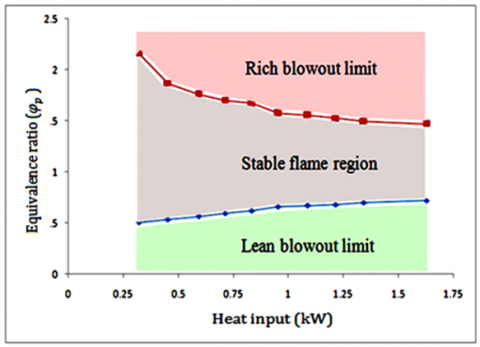
For premixed combustion, the stable flame zone is shown in Figure 6 for the case without a diffusion flame at central, It’s in term of equivalence ratio and heat input rate. This figure consists three regions of two paths. First zone represents lean blowout limit at this region may be accrued blow-off or flash-back, second one represents rich blowout limit where at this region the lift-off and unstable flame front, but between two zones of premixed flame at form of swirling was stable for equivalence ratios between 0.6 and 1.6, variation in the values between lean and rich blow-out less approximately at heat input of 1.25 kW. The lean-blow-out limit of liquid petroleum gas happens at equivalence ratios between 0.6 and 0.7, it can be shown that this swirling flame has a strong stabilization of flame border. Therefore, an equivalent ratio of φp=1.1 and heat input of 1.25 kW, which hardly produces a stable flame for given heat input rates, was temporarily chosen as the best equivalent ratio of the swirling flame. Thus, for all tests of experimental work the constant best value of equivalent ratio and heat input at premixed flame were obtain φp=1.1, HR=1.25kW.
The fluctuation of stable flame zones in the hybrid combustion is shown in Figure 7. Stable zone (I) gives the share stable region for two nozzles, and stable zone (II) gives the stable region only for nozzle (1). The using fuel nozzle (2) at axial direction with constant flow rate at tangential direction of swirling premixed, it’s also showing stable flame region (I) greater than stable flame region (II) because of the efficient mixing in the different fuel nozzles (1) lead to reduction in resident time as compared with fuel nozzle (2). Also noted at fuel nozzle (2) the stable flame region (I) reduces hardly with increasing the rate of heat input and overall equivalent ratio φo. The flame is unstable at heat input rate is over 1 kW at φo=0.8. On the other side, because the interactions between the swirling premixed and jet diffusion flames nozzle (1) have stable flames up to φo=0.7, although the heat input rate is 1.75 kW.
Figure 6. Stable flame region of the swirling premixed flame as a function of the heat input rate in the case of no axial fuel–air inlet
Figure 7. Variations of the stable flame region with two types of axial fuel nozzles in the (HC) mode
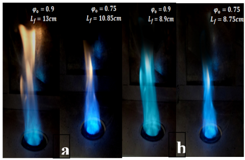
Figure 8. (a) Diffusion flame combustion; (b) Hybrid flame combustion
Figure 8 shows the instantaneous flame images of the diffusion and hybrid flam combustion under overall equivalent ratios (φo=0.9) and (φo=0.75), heat input rate of 0.8 kW. The photos were closely the same circumstances of high swirl by the air and mixture of the tangential nozzle. The equivalent ratio (φp) of the fuel–air mixture in the hybrid flame was fixed at 1.1 with value of heat input 1.25 kW to increase stable premixed flame. The flame color of the diffusion has a yellow close the flame tip, but the flame color is fully blue in the hybrid. It’s because a pure gaseous fuel in central core, this core is annulled by a zone in which the air and fuel diffuse inside and outside respectively.
4.2 Swirl number
Figure 9 shows the behavior of swirl number in a lean, stoicmetric and rich mixture at hybrid flame with a constant flow rate at tangential premixed with (φp=1.1, HR=1.25 kW). Figure 10 reveals the relation between axial air velocity and swirl number at different values of heat input. It was noted that the cyclone flow velocity enhancement, and due to increasing of centrifugal force a high circulating flow along the wall was generate. The fuel flow in axial direction has a helical flow motion with the air flow inward and outward the burner, thus leads to enhance in fuel-air mixing.
Figure 9. Profile of swirl number with annular air velocity of hybrid mode for three cases in term of equivalence ratio
Figure 10. Profile of swirl number with annular air velocity of hybrid mode for three cases in term of heat input
4.3 Flame temperature measurements
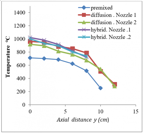
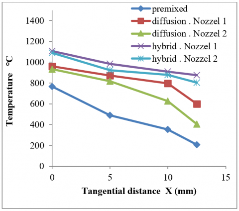
Figures 11 and 12 show the temperature distribution at lean mixture with equivalence ratio (φo=φp=0.8) for three types of combustion (premixed, diffusion and hybrid) flames combustion by using two types of fuel nozzles at axial and tangential direction. In each case, it was observed that the maximum temperature occurs at hybrid flame combustion. The temperature downstream from the flame decreases. This is because the absorption of the heat by the low-temperature area (convex zone).
Figure 11. Flame temperature distributions at lean mixture in axial distance at φ=0.8, HR=0.8 kW
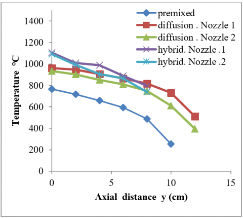
Figure 12. Flame temperature distributions at lean mixture in tangential distance at φ=0.8, HR=0.8 kW
The maximum value of temperature is at the lip of cyclone combustor, where the heat transfer is minimum at this point, Figures 13 and 14 manifest the temperature distribution at stoichiometric mixture with equivalence ratio (φo=φp=1). The increasing in temperature with flame stretching was noticed for all cases at each type of combustion, where the flame segments have different flame temperatures because the flame stretch lies continuously along the flame surface. Therefore, heat is conducted along the flame surface, and the temperature at the concave tip decreases, while the temperature at the segment adjoining the concave tip increases because of the heat addition. Furthermore, because a temperature gradient exists downstream, the heat conduction in such a direction may also affect the flame temperature.
Figure 13. Flame temperature distributions at stoichiometric mixture in axial distance at φ=1, HR=0.8 kW
Figure 14. Flame temperature distributions at stoichiometric mixture in tangential distance at φ=1, HR=0.8 kW
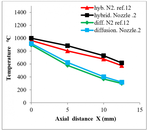
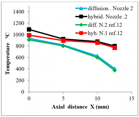
Figures 15 and 16 show the temperature distribution at rich mixture with equivalence ratio (φo=φp=1.2). The increasing in temperature with flame stretching was observed for all cases at each type of combustion by comparison with the lean and stoichiometric mixture, where the quantity of fuel increasing leads to enhance the heating value through combustion. The difference of flame temperature for same type of combustion mode at difference fuel nozzle, where the flame temperature at nozzle (1) is greater than at nozzle (2) because of the nature of mixing at the lip burner which leads to a complete combustion and burning more quantity of fuel at less time. Figures 17 and 18 comparison of the temperature distribution at lean mixture for diffusion and hybrid mode at nozzle 2. Figures 19 and 20 comparison of the temperature distribution at stoichiometric mixture for diffusion and hybrid mode at nozzle (2).
Figure 15. Flame temperature distributions at rich mixture in axial direction at φ=1.2, HR=0.8 kW
Figure 16. Flame temperature distributions at rich mixture in tangential direction at φ=1.2, HR=0.8 kW
Figure 17. Comparison of flame temperature distributions at lean mixture in axial distance at φ=0.8, HR=0.8 kW
Figure 18. Comparison of flame temperature distributions at lean mixture in tangential distance at φ=0.8, HR=0.8 kW
Figure 19. Comparison of flame temperature distributions at lean mixture in axial distance at φ=1, HR=0.8 kW
Figure 20. Comparison of flame temperature distributions at lean mixture in tangential distance at φ=1, HR=0.8 kW
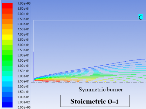
Figure 21 shows the numerically results of temperature profile of axisymmetric burner at lean (φD=0.8), stoichiometric (φD=1) and rich (φD=1.2) mixture. The simulated case which it represents diffusion flame combustion by using nozzle type 2. Because the diffusion of species (the mass fraction of interactions as shown in Figure 22) is maximum at lip of cylindrical burner it observed the high temperature at that area. For three cases of mixture, along the flame observed enhancement of temperature. The heat transfer by conduction through the burner wall effects on temperature gradient of flame. By comparison between experimental and numerical work in case of diffusion flame combustion nozzle (2) noted the different. The maximum temperature at lean mixture in experimental and numerical is 1,150 K, 1,240 K respectively, the temperatures in case of rich mixture reached to 2,200 K numerically and in case of stoichiometric mixture close to 1,750 K. That deferent temperature due to the numerically simulate of cyclone burner was assume isolation burner. Thus, the value of heat transfer through burner is zero.
Figure 21. Temperature profile numerically of diffusion flame, Nozzle (2)
Figure 22. Fuel mass fraction of diffusion flame, Nozzle (2)
Combustion of a cyclone hybrid combustor using a complex of premixed (swirling) and diffusion flames (jet) were experimentally achieved high stability of flame and low pollutant emissions. The main conclusions this study:
a. The comparisons in shape of flame between the hybrid and diffusion flame type which its represent indicate of blow-out regions.
b. The flame temperature at hybrid combustion is greater than in diffusion and premixed combustion, also the flame temperature which produced from nozzle (1) is greater than flame temperature at nozzle (2) for both hybrid and diffusion type.
c. Due to no flash-back and blow-out phenomena the hybrid flame limit of stability is large, and high-level stability at flame boarder.
d. A high swirl number was investigated by using premixed mode by tangential nozzles.
e. High temperature of diffusion flame which investigated numerically as compared with experimentally due to no heat transfer through burner.
|
Din |
Inner diameter of cyclone combustor |
(m) |
|
Do |
Outer diameter of cyclone combustor |
(m) |
|
L |
Length of cyclone combustor |
(m) |
|
Lf |
Flame length |
(m) |
|
SL |
Flame speed |
(m/s) |
|
SN |
Swirl Number |
|
|
Tair |
Air temperature |
(K) |
|
Tf |
Flame temperature |
(K) |
|
φo |
Overall equivalent ratio |
|
|
φp |
Equivalent ratio at premixed flame |
|
|
δ |
Flame thickness |
(mm) |
|
Ux |
Average velocity of air and fuel at diffusion mode in axial direction |
(m/s) |
|
Uθ |
Average velocity of air and fuel at premixed mode in tangential direction |
(m/s) |
[1] Lee, C.E., Oh, C.B., Kim, J.H. (2004). Numerical and experimental investigations of the NOx emission characteristics of CH4-air coflow jet flames. Fuel, 83(17-18): 2323-2334. https://doi.org/10.1016/j.fuel.2004.07.001
[2] Syred, N., Beer, J.M. (1974). Combustion in swirling flows: A review. Combustion and Flame, 23(2): 143-201. https://doi.org/10.1016/0010-2180(74)90057-1
[3] Ishizuka, S., Motodamari, T., Shimokuri, D. (2007). Rapidly mixed combustion in a tubular flame burner. Proceedings of the Combustion Institute, 31(1): 1085-1092. https://doi.org/10.1016/j.proci.2006.07.128
[4] Syred, C., Fick, W., Griffiths, A.J., Syred, N. (2004). Cyclone gasifier and cyclone combustor for the use of biomass derived gas in the operation of a small gas turbine in cogeneration plants. Fuel, 83(17-18): 2381-2392. https://doi.org/10.1016/j.fuel.2004.01.013
[5] Joo, N.R., Kim, H.Y., Chung, J.T., Park, S.I. (2002). The characteristics of pulverized coal combustion in the two stage cyclone combustor. Journal of Mechanical Science and Technology, 16(9): 1112-1120.
[6] Ishizuka, S. (1985). On the behavior of premixed flames in a rotating flow field: Establishment of tubular flames. In Symposium (International) on Combustion, 20(1): 287-294. https://doi.org/10.1016/S0082-0784(85)80513-0
[7] Shimokuri, D., Ishizuka, S. (2005). Flame stabilization with a tubular flame. Proceedings of the Combustion Institute, 30(1): 399-406. https://doi.org/10.1016/j.proci.2004.08.007
[8] Onuma, Y., Yamauchi, T., Mawatari, M., Morikawa, M., Noda, S. (2001). Low NOx combustion by a cyclone-jet combustor. JSME International Journal Series B Fluids and Thermal Engineering, 44(2): 299-304. https://doi.org/10.1299/jsmeb.44.299
[9] Hwang, C.H., Lee, S., Kim, J.H., Lee, C.E. (2009). An experimental study on flame stability and pollutant emission in a cyclone jet hybrid combustor. Applied Energy, 86(7-8): 1154-1161. https://doi.org/10.1016/j.apenergy.2008.10.016
[10] Noda, S., Inohae, J., Nakano, K., Onuma, Y. (2007). An experimental study of flame characteristics of jet diffusion flames in cylindrical furnaces (1 st Report, Effect of inner diameter of furnace on NOx emission properties). Journal of Environment and Engineering, 2(3): 505-513. https://doi.org/10.1299/jee.2.505
[11] Oh, J., Yoon, Y. (2010). Flame stabilization in a lifted non-premixed turbulent hydrogen jet with coaxial air. International Journal of Hydrogen Energy, 35(19): 10569-10579. https://doi.org/10.1016/j.ijhydene.2010.07.146
[12] Moussa, O., Driss, Z. (2017). Numerical investigation of the turbulence models effect on the combustion characteristics in a non-premixed turbulent flame methane-air. American Journal of Energy Research, 5: 85-93. https://doi.org/10.12691/ajer-5-3-3