Zahraa Albassam*![]() | Yaser Alaiwi
| Yaser Alaiwi![]()
© 2023 IIETA. This article is published by IIETA and is licensed under the CC BY 4.0 license (http://creativecommons.org/licenses/by/4.0/).
OPEN ACCESS
When a vehicle takes a turn at a high rate of speed, it is frequently rendered unstable, and the vehicle may lose touch with the way if the cornering is paired with a bump in the pavement. This can be especially dangerous if the vehicle is traveling in the opposite direction of the bump. The strategy asks for the design and manufacture of a suspension system and wheel assembly that are robust enough to withstand high speed cornering while also being able to ride comfortably over bumps of varied degrees of severity, Another crucial element of vehicle design is material choice since it allows us to lighten the vehicle while still maintaining the safety of the planned components, improving performance, We used the data and dimensions of the Honda Accord 2012, available in its own company, in our theoretical calculations to obtain the forces Depending on braking and bending conditions required to be applied to the components of the double wishbone suspension system which is made by solidworks2022 Where we selected the wishbone system's fundamental dimensions. Then, in order to determine the optimal materials for the Honda accord2012 double wishbone suspension system, a structural study is carried out with the aid of the ANSYS2021R2 program by modelling the loads exerted on just this suspension system individually using the wheel, wishbones, and knuckle. The suspension system's parts were then placed through some kind of series of quality control tests to make sure that only the best materials were utilized in their fabrication This is due to the fact that it is one of the most crucial sections of the vehicle. The results of this study were then used to refine the suspension system's design and select the best metals for it, by taking into account, among other things, the material's strength, cost of manufacture, weight, and availability. The purpose of the document, among other things, is to: A- Research all chassis parameters. B- Analyze a double wishbone suspension system parameter and try to optimize it. c) A study of the performance-influencing factors for the current suspension systems, d- To get the highest performance as well as material for a double wishbone suspension system, reduce or control the extent to which these aspects have an impact during the design phase.
designing, double wishbone, finite element analysis, optimization
For many people whose main priority is the ride, the suspension system may appear to be little more than a set of springs as well as shock absorbers connecting the wheels to the vehicle's frame. However, this view of a suspension system is incredibly oversimplified. The suspension system of an automobile is in charge of ensuring a smooth ride over difficult terrain, keeping the wheels in contact with the pavement, and reducing the amount of roll that the car suffers. the accessories for the suspension's treble major include the suspension system is made up of three main parts: a templet, which increases the strength of the vehicle and defines the suspension geometry; a spring, which converts kinetic energy into potential energy or even the opposite; and a shock absorber. which is a self-acting device designed to deflect kinetic energy. An automobile's suspension system, which even supports the vehicle's weight and connects the wheels to the car's frame. Theoretically, a suspension system should reduce a wheel's degrees of freedom (DOF) three rotational and three translational degrees of freedom which make up a 6-DOF simulation. Two coordinate systems are used to track a vehicle since it rotates and moves in both directions through the air [1]. from six to 2 (two degrees of freedom) on the rear axle and from three (3 degree of freedom) on the front axle, even though the suspension system must support push, steering, and braking as well as the forces involved with those functions, the total number of independent coordinates required to define motion is known as the system's degrees of freedom (DOF). Additionally, the number of degrees of freedom (DOF) is determined by multiplying the number of masses by the number of independent directions in which each mass can move [2]. It allows proportional movement between the wheels and the car’s structure. The relative movements of the wheels consist of vertical movement of a wheels, rotary motion about sidelong axes, and rotational motion about straight axes that are induced by the steering angle. The vertical movement of the wheels, the rotary motion about the sidelong axes, and the rotary motion about the straight axes which caused by the steering angle make up the relative motions of the wheels [3].
Encompass the necessary aspects of vehicle suspension systems and providing a soft estimate for their study and design [3], FEA was performed on the sample after it was sketched in the solid works software, followed by simulation in MATLAB and FEA in the Ansys program. Two theories of FEA were investigated, the first of which is the burden analysis of DWB as well as jerk absorbent yields up during exhaustion life as well as the concluding safety factor while a disfiguration. The model dissection was used to gain natural indecisions [4]. CATIA and Solid Works' design, along with ANSYS' analysis and MSC ADAMS' investigation of the suspension system's simulation, reduced the car's authority while improving its appearance [5]. SimMechanics and Simulink software toolboxes were used to develop a simulation of the quarters vehicle's double wishbone suspension [6]. CATIA software was used to prepare and analyze the pattern, calculate the stance for the center of gravity, and determine the roll center for a perfectly consistent, comfortable ride [7]. One can create a new arrangement. In this study, a unique disposition can reduce installation authority by 25%, and an additional 20% of that authority is available for additional orders. By adjusting the knuckle geometry, additional work is done to limit the variety of chamber angles [8]. investigated the creation and use of five popular suspension systems [9]. A simulation study was carried out to investigate the effect of the dynamic parameters of the suspension system [10]. discusses a variety of suspension system characteristics as well as the contributions made by various academics in this field [11]. provided an assessment of the overall spatial model of all these suspension systems' location kinematics [12]. An efficient numerical method is suggested for the kinematic analysis of the double wishbone suspension [13]. The study aims to offer a comprehensive finite element model of the dynamic behavior of the double wishbone vehicle suspension system with consideration for link flexibility [14]. Kinematic dissection took advantage of the current state; it was calculated that summation regarding aberration could be clearly minimized by choosing a suitable un-dive angle and that, through CAD software dissection, an abeyance method should be periodically repainted as dimensions, trends, and hard points change [15]. layout and analysis of wishbones, dampers, bell crank, and push rod, which includes all layouts, calculations, and applications of various features in elements, led to the creation of the ideal design with a high level of safety and minimal component stress [16]. Analysis showed that AISI4130 is the best material for A-arm items, and that this pattern requires pipes with an outer diameter of 1 inch and a thickness of 2 mm [17]. determined the component geometry and material properties as well as the system loads [18]. offers the following recommendation for a useful and affordable back suspension system: two links are found on a trailing arm [19]. The purpose of the paper's summary is to create a formula student car with enhanced steering control which also helps with twisting analysis of the suspension [20]. Comparing the proposed suspension system to three other previously created suspension systems [21]. It is suggested to synthesize the car suspension system using integrated kineto-dynamic analysis [22]. Explanation of the full specifications and pictures of the 2012 Honda Accord [23].
The automobile body and wheel are physically separated by the suspension system [6].
A. The ability of each wheel on an axle to move freely.
B. The utilization of suspension parts with modest masses that aren't wasted in order to keep as gentle of a wheel load fluctuation as is possible.
C. Cost [7].
4.1 The growth strategy
In the creation of the entire system, which also is carried out in two stages, the verification or evaluation of the system happens that after mechanical creation of the system.
The following actions were taken as the system was being designed:
Part A: Mechanical design
1. Decide on the type of suspension system to be employed.
2. Determine the basic parameters, such as wheelbase, track width, as well as the centre of gravity, in addition to height, tyres, wheels, or other suspension adjustments.
3. For the design, make knuckles and wishbones.
4. Springs for layout Part.
Part B: The system has been tested.
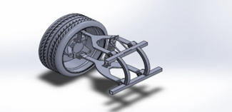
Figure 1. Double wishbone suspension system
4.1.1 Various types of suspension systems
A- wishbone suspension system.
B- macpherson strut suspension system.
C- rigid suspension system [11].
4.2 Honda accord 2012
4.2.1 Summary of Honda accord 2012
A fantastic used midsize automobile choice is the 2012 Honda Accord shown in Figure 2. Although the cargo is on the tiny side, the cabin is rather roomy, and it survived all safety tests and obtained an above-average grade for dependability. The Accord's interior actually resembles that of a large automobile more than a medium one. By providing more powertrain choices and more agile handling, the 2012 Accord exceeds the majority of rivals in terms of performance. High grades for safety were given to the 2012 Honda Accord. The sedan got the top score of Good in each of the Insurance Center for Highway Safety's four crash tests. The 2012 Accord scored a perfect five stars in each of the three crash tests conducted by the Highway Traffic Safety Administration. It also achieved five stars for overall safety. The IIHS did not test the 2012 Honda Accord coupe, although the NHTSA gave it 5-star rating for rollover resistance. The 2012 Honda Accord makes use of the advantages of a high-end chassis design to provide pleasant and elegant handling dynamics. A world-class ride and performance on winding roads, lengthy expanses of major highway, and bad weather are provided by a double-wishbone forward suspension as well as a multi-link rear suspension. With this independent suspension system, the car's ride comfort, traction, and stability are all increased while the amount of unsprung mass is decreased [14]. The ability to drive in the snow is improved, and more unpaved roads are accessible with a six-inch ground clearance. Four-wheel disc brakes, front and back stabilizer bars, and electronic stability control, sometimes referred to as Vehicle Stability AssistTM (VSATM), are all included as standard equipment.
Figure 2. Honda accord 2012 [23]
4.2.2 General vehicle characteristics
When considering a vehicle's handling and wheel travel capabilities, its suspension system is of utmost importance. Additionally, the hub and knuckle are designed using the results of a suspension geometry study to determine the various geometry angles [16]. Fundamental suspension geometry can be used to calculate wheel travel and grip conditions, but for more extreme situations, a FEA analysis will be needed. The calculation of the stresses caused by the excessive displacements caused by cornering is the main goal of this analysis utilizing finite elements. A vehicle's suspension system is exposed to a variety of stressors as a result of various road and driving conditions but rounding turns and driving over bumps create the most severe strains and pose the biggest threat to the vehicle's capability to keep its ability to manage the road. This study will look at the scenario involving turning at high speeds. As a result, Table 1 offers a summary of the vehicle characteristics that are used in determining the loads exerted on the suspension system [18].
4.2.3 Purposes of the suspension design
As the automotive suspension system was being developed, the major design objective was to maximize the effectiveness of a passenger's vehicle's ride comfort [22]. Suspensions are made to maintain a greater portion of tire in contact with the ground, which enhances the handling of the car [15]. If the suspension were ideal, it would be capable of lowering the car's chassis and bring its parts closer to the ground [20]. To isolate the vehicle's chassis from road vibrations is one of a suspension system's primary functions [21].
The following are the primary objectives of a suspension system's design:
A. To increase the connection patch and, thus, handling by minimizing variations of camber and toe even as wheel rotates.
B. To lessen unsprung mass so the vehicle can perform better and have better traction on rocky terrain [19].
5.1 Wheel calculations
We must first identify the potential forces that might be applied to the A arm for the wishbone suspension system in order to analyze it. Once we've completed that, we can proceed to the following phase of the procedure.
These groups of forces include:
1. The quantity of force applied to the brakes when they are pressed.
2. The stress that is applied to the vehicle during cornering as a result of the imposed angular acceleration.
3. Vertical Force, also referred to as calculating the greatest load applied that it can support.
4. Frictional energy
5. Bumper Force, sometimes referred to as vibration induced by the road, is the force that is applied to the A arm [17].
Table 1. General characteristics of the vehicle
|
Values |
Property |
Symbols |
|
1285kg |
car weight |
M |
|
2.79m |
wheel base |
WB |
|
51(r), 49(f) |
mass distribution |
mR:mF |
|
0.45m |
gravity's center (cg) |
Hcg |
|
0.49 |
weight distribution in the front |
Wdis |
|
0.5 |
weight distribution in the rear |
Wdis |
|
RF =1.590 m |
tracks in the front and rear |
R |
|
RR = 1.590 m |
||
|
239 N-m @ 2450.4 m/s |
horsepower |
P |
|
218.28@ 450.2(N-m @ m/s) |
torque |
T |
|
11.49 m |
turning diameter, curb-to-curb |
Dt |
|
194.9 in,4.95m |
length |
L |
|
58.1 in,1.475m |
height |
H |
|
72.7 in,1.846m |
width |
W |
5.1.1 Breaking force, a=1 g
Wtot $($ linear $)=\frac{\mathrm{a} * \mathrm{Hcg} * \mathrm{M}}{2 * \mathrm{~W}_B}$. Wtot $($ Linear $)=107 \mathrm{~kg}$ (1)
Lvertical on the wheel $=\frac{\mathrm{M} * \mathrm{~W}_{\text {dis }}}{2}+$ WtLinear $*$$g$. Lvert on the wheel $=1364.4 \mathrm{~N}$ (2)
$\begin{array}{rl}\mathrm{F}_F=\text { Lvertial } * & \mathrm{Fc} . \mathrm{F}_{\mathrm{F}}=1364.4 * 0.8 \, \cdot \, \mathrm{F}_{\mathrm{F}}= & 1091.52 \mathrm{~N}\end{array}$ (3)
FUpright $=\frac{\mathrm{Fy}}{2} \, \cdot \, \mathrm{FU}=545.76 \mathrm{~N}$ (4)
5.1.2 Cornering force, a=4
Wtlateral $=\frac{\mathrm{a} * \mathrm{Hcg} * \mathrm{M} * \mathrm{~W}_{\text {dis }}}{\mathrm{g} * R t}$ $\, \cdot \,$ WtLateral $=74 \mathrm{~kg}$ (5)
Lvertical on the wheel $=\frac{\mathrm{M} * \mathrm{~W}_{\text {dis }}}{2} *$ Wtlat $*$ g. Lvertical$=1040.76 \mathrm{~N}$ (6)
$\mathrm{F}_F=$ Lvertical $* F c . \mathrm{F}_{\mathrm{F}}=832.608 \mathrm{~N}$ (7)
Moment due to friction=249.7 N-m:
$\mathrm{F}_{\mathrm{Ua}}=\frac{\text { Moment due to friction }}{\text { Length of A - arm upper }} \, \, \, \cdot \, \, \,\mathrm{F}_{\mathrm{Ua}}=2312 \mathrm{~N}$ (8)
Fupright at lower point $=$$\frac{\text { Moment due to friction }}{\text { Length of A-arm lower }} \, \, \, \cdot \, \, \, F_{U L}=1836 \mathrm{~N}$ (9)
5.1.3 Centrifugal force
Vehicle travelling over a bump of 20m at 45Kmph:
$\mathrm{Fc}=\left(\frac{\mathrm{M} * \mathrm{~W}_{\mathrm{dis}}}{2 * \mathrm{br}}\right) *$ velocity $^2 \cdot \mathrm{Fc}=2459.5 \mathrm{~N}$ (10)
5.2 Calculations of steering knuckle
Table 2. Knuckle loading condition
|
Values |
Property |
Symbols |
|
1.5mg |
Braking force |
FB |
|
1.5mg |
Lateral force |
FL |
|
45-50N |
Steering force |
FS |
|
3mg |
Force on knuckle hub in x - axis |
FHx |
|
3mg |
Force on knuckle hub in y - axis |
FHy |
|
1mg |
Force on knuckle hub in z- axis |
FHz |
If we consider the steering knuckle configuration for a car weighing 1295kg, the braking force creates a moment when it acts on it, which we can express using the following equations.
5.2.1 Formulas for knuckles
The Bracking force=1.5 Mg
The Bracking force=4763.98 N
Moment $=F_B *$ vertical Distance. $M=447814.12 N-m m \text { (For one } \text { wheel })$ (11)
Force on the X-axis knuckle hub=3 mg
$\mathrm{X}$ - axis force on the knuckle hub equals $\mathrm{Y}-$ axis force $=9527.9 \mathrm{~N}$ (12)
Force on the Z-axis knuckle hub=1 Mg
Force on the Z-axis knuckle hub= 3175.9 as shown in Table 2.
Ftot $=\sqrt{(F X)^2+(F Y)^2+(F Z)^2}$
Fto= 13843.7 N
5.3 Materials for a double wishbone system's components
5.3.1 Material selection for the wheels and knuckle
When choosing a material for the wheel assembly shown as Table 3, keep the following objectives in mind: Keeping the weight low helps race cars maintain a competitive performance-to-weight ratio. achieving the ideal stiffness level that maintains the intended geometry while minimizing system compliance. The metals Al6061, Titanium Alloy, and Aluminum Alloy for the wheel and Al6061, Gray Cast Iron, and Aluminum Alloy for the knuckle are shown in Table 4 were considered based on their availability and costs in the market.
Table 3. Properties of wheel materials
|
Unit |
Aluminum alloy |
Al 6061 |
Titanium alloy |
Property |
|
kg m-3 |
2770 |
2713 |
4620 |
Density |
|
Pa |
7.10E+10 |
6.90E+10 |
9.60E+10 |
Young modulus |
|
0.33 |
0.33 |
0.36 |
Position ratio |
|
|
Pa |
2.67E+10 |
2.60E+10 |
3.53E+10 |
Shear modulus |
|
Pa |
2.80E+08 |
2.59E+08 |
9.30E+08 |
Tensile yield strength |
|
Pa |
2.80E+08 |
3.13E+08 |
9.30E+08 |
Compressive yield strength |
|
Pa |
3.10E+08 |
1.07E+09 |
Tensile ultimate strength |
Table 4. Properties of knuckle materials
|
Unit |
Aluminum Alloy |
Al 6061 |
Gray cast iron |
Property |
|
kg m-3 |
2770 |
2713 |
7200 |
Density |
|
Pa |
7.10E+10 |
6.90E+10 |
1.10E+11 |
Young modulus |
|
0.33 |
0.33 |
0.28 |
Position Ratio |
|
|
Pa |
2.67E+10 |
2.60E+10 |
4.30E+10 |
Shear modulus |
|
Pa |
2.80E+08 |
2.59E+08 |
0 |
Tensile yield strength |
|
Pa |
3.10E+08 |
3.13E+08 |
2.40E+08 |
Tensile Ultimate strength |
5.3.2 Wishbone material choice
The metal used for the wishbone is shown in Table 5 must satisfy the following requirements: it must be strong enough to sustain the loads placed upon that when it's in dynamic circumstances. Al6061, AISI 4140, and AISI 1020 were all taken into consideration based on their pricing and marketability.
Table 5. Properties of wishbone materials
|
Units |
Al 6061 |
AISI 4140 |
AISI 1020 |
Property |
|
kg m-3 |
2713 |
7850 |
7850 |
Density |
|
Pa |
6.90E+10 |
2.13E+11 |
2.12E+11 |
Young modulus |
|
0.33 |
0.29 |
0.29 |
Position ratio |
|
|
Pa |
2.60E+10 |
8.24E+10 |
8.23E+10 |
Shear modulus |
|
Pa |
2.59E+08 |
6.52E+08 |
2.94E+08 |
Tensile yield strength |
|
Pa |
3.13E+08 |
1.02E+09 |
3.93E+08 |
Tensile ultimate strength |
6.1 Analysis of wheel
Utilizing ANSYS software, the static analysis of the wheel is examined, and the sample is designed using Solidworks2022. Considerations for the analysis of a wheel include braking force, cornering force, gravitational forces, and initially applied Cornering force is determined via vertical load as well as frictional force (Eq. (2,3). in the Y and Z axes) and braking force is determined by both. In the Y and Z axes as Eq. (6).and as Eq. (7). assess centrifugal force in the Y axis, Eq. (10). and establish support at the point where the knuckle and wheel make contact.
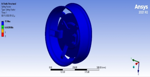
6.1.1 Results of simulation with titanium alloy wheel
First, we calculated the equivalent von Mises stress distribution, deflection/deformation, and safety factor employing titanium alloy utilizing a combined simulation program, Safety factor of titanium alloy shown in Figure 3, Equivalent stress of titanium alloy shown in Figure 4.
The results are displayed below:
Figure 3. Safety factor of titanium alloy wheel
Figure 4. Equivalent stress of titanium alloy wheel
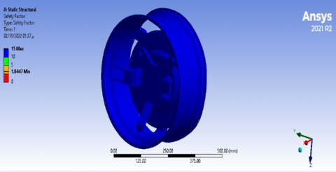
Figure 5. Safety factor of Al6061wheel
Figure 6. Equivaent stress of AL6061 wheel
6.1.2 Results of simulation with Al6061 wheel
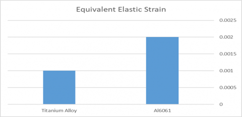
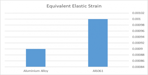
Then, using the AL6061 wheel material, we ran a simulation to calculate the safety factor, equivalent von Mises stress distribution, and deflection/deformation. The results are summarized as follows, Safety factor of Al6061 shown in Figure 5, Equivalent stress of AL6061 shown in Figure 6, Scheme of equivalent stress titanium alloy&Al6061wheel shown in Figure 7, Scheme of equivalent elastic strain titanium alloy&Al6061wheel shown in Figure 8.
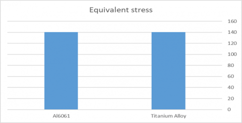
6.1.3 Schemes of equivalent (stress, strain) wheel
Figure 7. Scheme of equivalent stress titanium alloy&Al6061wheel
Figure 8. Scheme of equivalent elastic strain titanium alloy&Al6061wheel
6.2 Analysis of knuckle
ANSYS software is used to analyze the static analysis of the knuckle, and the sample was also designed using Solidworks2022. Several other forces are also at playas Eq. (11) and as Eq. (12) such as the loads on the knuckle hub in the X, Y, and Z directions, as well as braking force, the moment, a lateral force, a steering force, as well as the loads in the lateral direction. Figures, which show the following findings from the analyses, are numerous and include:
6.2.1 Simulation with Al6061 knuckle
We started by simulating Deflection/Deformation, equivalent von Mises Stress Distribution, and Safety Factor together using Al6061 material. The conclusions are summarized as follows. Safety factor of Al6061shown in Figure 9, Equivalent stress of Al6061shown in Figure 10.
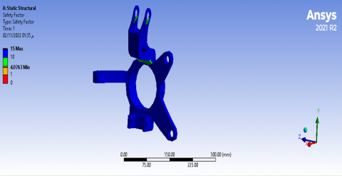
Figure 9. Safety factor of Al6061 knuckle
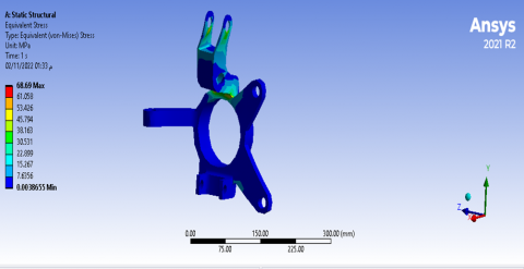
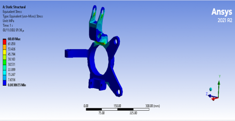
Figure 10. Equivalent stress of Al6061knuckle
Figure 11. Safety factor of aluminum alloy knuckle
Figure 12. Equivalent stress of aluminum alloy knuckle
6.2.2 Simulation with Aluminum Alloy knuckle
The simulation of combined deflection/deformation, equivalent Von Mises stresses distribution, and safety factor was then carried out using Aluminum Alloy material. These are the results. Safety factor of aluminum alloy shown in Figure 11, Equivalent stress of aluminum alloy shown in Figure 12, Scheme of equivalent stress aluminum alloy&Al6061 knuckle shown in Figure 13, Scheme of equivalent elastic strain aluminum alloy&Al6061knuckle shown in Figure 14.
6.2.3 Schemes of (stress, strain) knuckle
Figure 13. Scheme of equivalent stress aluminum alloy&Al6061 knuckle
Figure 14. Scheme of equivalent elastic strain aluminum alloy&Al6061knuckle
6.3 Analysis of wishbone
The layout was created using Solidworks2022, then it was subjected to an analysis using Ansys2021R2, and finally two loads were imposed to the top arm and the lower arm as Eq. (8) and as Eq. (9).
6.3.1 Simulation with steel 1020 of wishbone
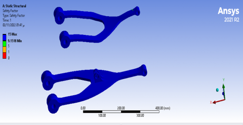
Following that, steel1020 was used as the material for the integrated simulation for deflection/deformation, equivalent Mises stress distribution, as well as safety factor. Safety factor of AISI1020 that shown in Figure 15, Equivalent stress of AISI1020shown in Figure 16.
Figure 15. Safety factor of AISI1020 wishbone
Figure 16. Equivalent stress of AISI1020 wishbone
6.3.2 Simulation with AISI4140 wishbone
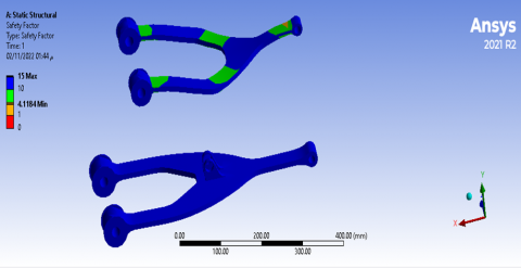
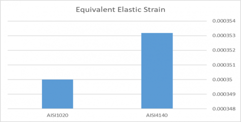
Following that, AISI4140 was used as the material of choice for the simulation that included deflection/deformation, equivalent Mises stress distribution, as well as safety factor. The repercussions include Safety factor of AISI4140 shown in Figure 17, Equivalent stress of AISI4140shown in Figure 18, Scheme of equivalent stress AISI1020&AISI4140 shown in Figure 19, Scheme of equivalent elastic strain AIS4140&AISI1020 wishbone shown in Figure 20.
Figure 17. Safety factor of AISI4140wishbone
Figure 18. Equivalent stress of AISI4140wishbone
6.3.3 Schemes of (stress, strain) wishbone
Figure 19. Scheme of equivalent stress AISI1020&AISI4140 wishbone
Figure 20. Scheme of equivalent elastic strain AIS4140&AISI1020 wishbone
The materials needed to build a double wishbone, a wheel, and a knuckle were analyzed using the Ansys2021R2 program, and the best material was selected based on the findings of the tests and its availability on the market, regardless of how much it costs to make. These materials share many mechanical properties, such as high hardness, high thermal conductivity, little thermal expansion, low specific density, and considerable resistance of heat and corrosion. These materials also have a limited specific density. When we comparison the materials we chose for the wishbone AISI1020, and AISI4140 we chose AISI 4140 as a result of qualities it possesses in terms of safety factor, deformation, and equivalent stress. We also chose aluminum alloy for the knuckle because it outperforms aluminum 6061 in terms of safety factor, deformation, and equivalent stress. As a conclusion, we made the decision to use titanium for the wheels for our car, the purpose of this research was to offer suspension designers a place to begin their work as well as a condensed review of the aspects that play a role in the creation of suspension systems, With the assistance of computer analysis, the aims of reliability and manufacturability were also accomplished through the selection of materials and the physical design of the product, and in the future we can Select another materials that are different from the ones we tested and Study the dynamic analytical study for the suspension system.
The Altinbas University funded this research.
|
Hcg |
Height of the Center of Gravity |
|
m |
automobile mass kg |
|
WB |
wheels base m |
|
Ff |
friction of force N |
|
Fc |
friction cofficient |
|
FU |
force on the upright knuckle N |
|
Wdis |
weight distribution in the rear |
|
br |
the distance which the vehicle travelling over a bump |
|
Subscripts |
|
|
Wtot(linear) |
Transfer of Linear Weight |
|
Wdis |
distribution of weight |
|
Rt |
width of the track |
|
Wtot(lat) |
transfer of lateral load |
|
Bl |
braking's perpendicular load |
|
Fb(up) |
the upper arms bumb force |
|
Fb(lo) |
the lower arms bumb force |
|
Fupr |
the upright arms force |
|
Flaw |
lower arm force |
[1] McNeely, B. (2005). Introduction to 6-DoF haptic display. SIGGRAPH '05: ACM SIGGRAPH 2005 CoursesJuly 2005, pp. 18-es. https://doi.org/10.1145/1198555.1198623
[2] Keviczky, L., Bányász, C. (2015). Two-Degree-of-Freedom Control Systems: The Youla Parameterization Approach. Academic Press. https://doi.org/10.1016/c2014-0-02908-5
[3] Goodarzi, A., Khajepour, A. (2017). Vehicle Suspension System Technology and Design. Springer Cham. https://doi.org/10.1007/978-3-031-01494-9
[4] Ahmed, M.A., Mujavar, M.M.H., Akbar, M.M., Dakhani, M.M.S. (2018). Design and analysis of double wishbone suspension system using fea and matlab. International Journal of Engineering Research & Technology (IJERT), 7(5): 445-450.
[5] Swami, M.S., Satpute, O., Jadhav, V., Mohite, C., Kumbhar, R. (2019). Design & manufacturing of double wishbone suspension and wheel assembly for formula style vehicle. International Research Journal of Engineering and Technology, 6(6): 1348-1354.
[6] Tandel, A., Deshpande, A.R., Deshmukh, S.P., Jagtap, K.R. (2014). Modeling, analysis and PID controller implementation on double wishbone suspension using SimMechanics and Simulink. Procedia Engineering, 97: 1274-1281. https://doi.org/10.1016/j.proeng.2014.12.406
[7] Patankar, A., Kulkarni, R., Kothawade, S., Ingale, S. (2016). Design and development of a transmission system for an all terrain vehicle. International Journal of Mechanical Engineering and Technology (IJMET), 7(3): 351-359.
[8] Thakare, S.A., Antapurkar, P.C., Shah, D.S., Dhamangaonkar, P.R., Sapali, S.N. (2017). Design and analysis of modified front double wishbone suspension for a three wheel hybrid vehicle. 2017 International Conference on Nascent Technologies in Engineering (ICNTE), pp. 1283-1286. https://doi.org/10.1109/icnte.2017.7947899
[9] Anglin, D.L. (2019). Automotive suspension. In: AccessScience. McGraw Hill. https://doi.org/10.1036/1097-8542.064600
[10] Kavitha, C., Shankar, S.A., Ashok, B., Ashok, S.D., Ahmed, H., Kaisan, M.U. (2018). Adaptive suspension strategy for a double wishbone suspension through camber and toe optimization. Engineering Science and Technology, an International Journal, 21(1): 149-158. https://doi.org/10.1016/j.jestch.2018.02.003
[11] Pradhan, P., Singh, D. (2021). Review on air suspension system. Materials Today: Proceedings. https://doi.org/10.1016/j.matpr.2021.03.640
[12] Reddy, K.V., Kodati, M., Chatra, K., Bandyopadhyay, S. (2016). A comprehensive kinematic analysis of the double wishbone and MacPherson strut suspension systems. Mechanism and Machine Theory, 105: 441-470. https://doi.org/10.1016/j.mechmachtheory.2016.06.001
[13] Attia, H.A. (2000). Numerical kinematic analysis of the double wishbone motor-vehicle suspension system. Transactions of the Canadian Society for Mechanical Engineering, 24(2): 391-399. https://doi.org/10.1115/detc2000/dac-14537
[14] Nabawy, A.E., Abdelrahman, A.A., Abdalla, W.S., Abdelhaleem, A.M., Alieldin, S.S. (2019). Analysis of the dynamic behavior of the double wishbone suspension system. International Journal of Applied Mechanics, 11(5): 1950044. https://doi.org/10.1142/s1758825119500443
[15] Tanik, E., Parlaktaş, V. (2016). On the analysis of double wishbone suspension regarding steering input and anti-dive/lift effect. Journal of Advanced Mechanical Design, Systems, and Manufacturing, 10(2): JAMDSM0032-JAMDSM0032. https://doi.org/10.1299/jamdsm.2016jamdsm0032
[16] Nagar, A.K.R.R.A., Saxena, H.G.G. (1997). Design and analysis of suspension component of F1 prototype. SAE International in United States. https://doi.org/10.4271/972691
[17] Upadhyay, P., Deep, M., Dwivedi, A., Agarwal, A., Bansal, P., Sharma, P. (2020). Design and analysis of double wishbone suspension system. In IOP Conference Series: Materials Science and Engineering, 748(1): 012020. https://doi.org/10.15623/ijret.2014.0315165
[18] Nabawy, A., Abdelrahman, A., Abdelhaleem, A., Alieldin, S. (2019). Finite element analysis of double wishbone vehicle suspension system. The Egyptian International Journal of Engineering Sciences and Technology, 27: 12-22. https://doi.org/10.21608/eijest.2019.97275
[19] Kumar, P., Emmanuel, S., Mathivanan, N.R. (2019). Design and finite element simulation of a trailing arm suspension system. In: Prasad, A., Gupta, S., Tyagi, R. (eds) Advances in Engineering Design . Lecture Notes in Mechanical Engineering. Springer, Singapore. https://doi.org/10.1007/978-981-13-6469-3_21
[20] Wagh, S.Y., Nandi, E.A. (2020). Design and analysis of double wishbone suspension for formula student car. IRJET, 9(9): IJERTV9IS090137. https://doi.org/10.17577/ijertv9is090137
[21] Kashem, S., Nagarajah, R., Ektesabi, M. (2018). Vehicle Suspension Systems and Electromagnetic Dampers. Springer Singapore. https://doi.org/10.1007/978-981-10-5478-5
[22] Balike, K.P., Rakheja, S., Stiharu, I. (2011). Development of kineto-dynamic quarter-car model for synthesis of a double wishbone suspension. Vehicle System Dynamics, 49(1-2): 107-128.https://doi.org/10.1080/00423110903401905
[23] Schedel, R. (2008). The new honda accord. ATZautotechnology, 8: 34-36. https://doi.org/10.1007/bf03247057