Hasan S. Majdi![]() | Wajeeh K. Hasan
| Wajeeh K. Hasan![]() | Mohammed A. Mahmood Hussein
| Mohammed A. Mahmood Hussein![]() | Laith J. Habeeb*
| Laith J. Habeeb*![]()
© 2023 IIETA. This article is published by IIETA and is licensed under the CC BY 4.0 license (http://creativecommons.org/licenses/by/4.0/).
OPEN ACCESS
One of the best solutions for the heat exchange is the plate heat exchangers, which are characterized by high thermal efficiency. Where in this paper work has been done on a plate heat exchanger with dimensions appropriate to its practical application and changing the fluid exit areas to increase the surface area of exchange. And the use of more than one class to see the improvements and changes that can be analyzed and benefited from the first part represents the heat exchanger with a direct direction and the change in the number of plates. Where two sets of models were designed, the first representing the change in the number of plates, where 10, 20 and 30 plates were used to irrigate the real rate of increasing the number of plates. As for the second part, it represents the heat exchanger with a reverse path and compare them with each other. The result show that when increasing the number of plates in the plate heat exchanger, it increases the transfer area and thus increases the value of the transferred heat energy. In the case where the best transfer of heat energy is compared to 20 and 10 blades, where the exit temperature reached 308.1 K, it is noticing an increase in the transfer of thermal energy.
ANSYS simulation, CFD, solid works program, FEM, flow distribution, numerical study, plate heat exchanger, pressure drops
A laminar counter stream inside a little channels plate heat exchanger outfitted with Y and C structure boundaries was mathematically dissected. The presence of the formed ribs further develops heat transmission and liquid disturbance, as indicated by the outcomes. The Y and C ribs have maximal THPP values that are around 1.44 and 2.6 times that of a smooth pipe, individually [1]. Fluid misalignment between parallel channels is a major problem in plate heat exchanger applications. An experimental analysis of the single-phase flow distribution in brazed plate heat exchangers is presented in this work. The probes put into the headers measure the pressure profile in the heat exchanger. The observed pressure drop throughout the channels and the calculated in-channel friction factor correlate define flow distribution [2]. The warm exhibition of an intensity exchanger with and without splitter plates associated with the cylinders is examined. Connections limit pressure drop and raise the Nusselt number, bringing about superior generally warm execution for heat exchangers. Heat transmission is insignificantly helped by around 7% when the splitter thickness is raised up to generally 20% of the line distance across. The tension drop is additionally altogether upgraded by generally 20% [3]. Thermally-driven absorption systems based on the lithium bromide and water pair are extensively used in a variety of industrial areas. A recuperator warms a working fluid before it reaches an absorption system generator, lowering the needed heating load. The flow properties of chevron plate heat exchangers of various structural dimensions were predicted using computational fluid dynamics (CFD). The optimal dimensions in terms of heat transfer rate and friction factor were chosen [4]. Pillow Plate Heat Exchangers (PPHX) are PHXs with a complicated wavy structure and favorable thermal-hydraulic properties. PPHXs are more often utilized in the chemical and process industries, with less study in the heating, ventilation, air conditioning, and refrigeration industries. When compared to the baseline design with round spot welds, there is a potential improvement of up to 36% in heat transfer coefficient and a 67 percent reduction in pressure drop [5]. A prescribed report to expand the exhibition of PHEs is lung designed plates made utilizing the biomimetic approach. To further develop the intensity transmission region, plate surfaces were created as a 3D lung-like shape. When contrasted with the reference PHE, the outcomes uncover a 71.30 percent expansion in heat transmission and a 67.8 percent decrease in pressure drop for 6.66 percent less volume [6]. Plate Heat Exchangers (PHEs) are lightweight, proficient, and generally utilized in various areas. There is a dire requirement for nitty gritty and intensive concentrate on the intensity move and liquid stream properties of different kinds of exchangers. Plate balance heat exchangers are a type of minimal exchanger that comprises of a pile of rotating level plates called segment sheets and ridged blades that are brazed together as blocks [7]. This research focuses on developing a numerical model to mimic the condensation process of ammonia, a commonly used natural refrigerant, inside a Plate Heat Exchanger (PHE). A validation test case is used to verify the simulation's plausibility based on the pressure drop and heat flow data. A comment on the correctness of the CFD simulation is provided [8]. Plate Heat Exchangers (PHE) transport much more heat. The purpose of this research is to look at the heat transfer properties of a commercial corrugated PHE with sinusoidal corrugation. The mesh for the PHE was created using a sophisticated meshing process. The total research for 60°/60° chevron angle plate (β) was carried out over a broad range of Re and Prandtl value [9]. Computational fluid dynamics (CFD) simulation is used to show the heat transfer and flow properties of a novel plate heat exchanger. The findings reveal that the corrugation angle may induce a non-active heat transport regime to arise. To improve heat transfer performance, an ideal shape of current plate heat exchanger is presented [10]. The growing need for energy savings in industry has resulted in several studies to enhance the thermal performance of heat exchangers. The performance of PPHEs is investigated using numerical simulation in this work. The findings indicate that the geometrical characteristics of a PPHE have a substantial impact on thermal performance and energy efficiency. The height of pillow plate channels, as well as the longitudinal and transverse spacing of welding sites, are among the characteristics taken into account [11]. Fouling in rough preheat trains is a critical supporter of warm shortcoming in petrol processing plants. Utilizing discrete-stage CFD reenactments, the exploration looks to imitate the testimony of asphaltenes from unrefined petroleum in a multi-pass shell and cylinder heat exchanger. Gravity, drag, Saffman lift, and thermophoretic powers are completely applied to particles to decide their testimony speeds. Gravity and drag are the main considerations that invigorate molecule statement, though low thickness and temperature slopes favor more noteworthy molecule testimony rates [12]. The objective is to explore heat transport properties in the PHE both tentatively and mathematically. To stay away from sedimentation and flocculation, nanofluid is produced by using TiO2 nanoparticles in the ideal size and blending proportion in with surfactant. This methodology likewise maintains a strategic distance from molecule assortment inside an intensity exchanger. The essential objective of this examination is to estimate the warm properties of nanofluids in a plate heat exchanger [13]. Plate heat exchangers with offset-strip balances or dimple-type turbulators are broadly utilized as oil coolers for gas powered motors and gearboxes in the auto business. Their improvement is a troublesome endeavor since it requires accomplishing three particular objectives: high minimization, low tension drop, and extraordinary intensity move proficiency. The accessibility of exact Computational Fluid Dynamics (CFD) reenactment models is basic during the plan cycle in this unique situation [14]. The objective of this attempt is to further develop fabricating processes for dairy items like yogurt. Surface misfortunes have been seen all through their creation to far, bringing about a fall in thickness contrasted with the expected quality on the completed item. Computational Fluid Dynamics can evaluate mechanical pressure and proposition data makers can't get to by and by breaking down the way of behaving of yogurt in a plate heat exchanger [15]. To analyze the impact of half and half nanofluid (Al2O3 + MWCNT/water) on heat move and strain drop attributes, mathematical and exploratory examinations on the plate heat exchanger were directed. CFD programming was used to examine using a discrete stage model. The intensity move coefficient has expanded by 39.16 percent (merit), with a 1.23 percent expansion in siphoning power (bad mark) [16]. Plate Heat Exchangers (PHEs) are lightweight, productive, and generally utilized in different areas. There is a critical requirement for point by point and exhaustive concentrate on the intensity move and liquid stream properties of different kinds of exchangers. Plate blade heat exchangers are a type of minimized exchanger that comprises of a heap of rotating level plates called parcel sheets and folded balances that are brazed together as blocks [17]. The subject of this exploration is choppiness displaying of liquid stream in channels of plate heat exchangers used to warm private boiling water in a Belgrade warming substation. The functional productivity and cost-viability of these not entirely settled by working out the genuine stream systems under differing circumstances. The not entirely set in stone by the exchangers' warm capability and contamination, which affects the expense of keeping up with the radiators [18]. Other workers [19-22] experimented with and revised heat exchangers using many approaches and liquids. The heat transfer by heat exchangers has been analyzed and improved by forced convection, oil fouling in a double pipe, copper oxide nanofluid, and an electromagnetism-like algorithm. In addition, Tarrad [23] studied borehole thermal analysis for a closed loop vertical U-tube DX ground heat exchanger. Excellent agreement between the projected thermal resistance and other previously published research in this field was found. Finally, Abbas and Mohammed [24] studied augmentation of plate-fin heat exchanger performance with support of various types of fin configurations. It can be seen that using the OSF configuration results in values for the triangular configuration having a higher f-factor.
The study of heat exchangers requires the study of correct solutions that increase the thermal efficiency of heat exchangers. Through previous research, it is noted that the study that was conducted before interfered with cracks inside the plates, and this increases the pressure difference. As for this research paper, it was centered on changing and prolonging the fluid path. To cover it the necessary time for heat exchange.
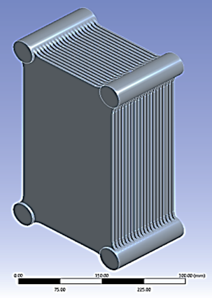
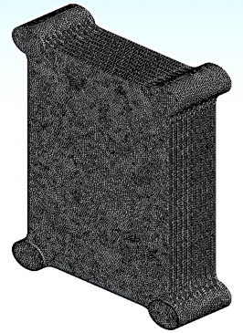
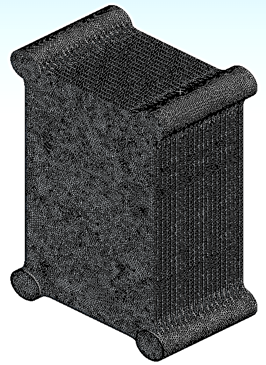
One of the most prominent engineering design programs known at the present time is the solid work program, which can design engineering models with great accuracy and care. Where the design of the heat exchanger is Figure 1.
Figure 1. Geometry design
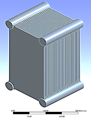
Where two sets of models were designed, the first representing the change in the number of plates, where 10, 20 and 30 plates were used to irrigate the real rate of increasing the number of plates as shown in Figure 2. As for the second group, it represented the opposite direction of flow, where the entrance to the upper heat exchanger and the exit from the bottom are in one plate, and so the process is repeated until reaching the exit area.
(a)
(b)
(c)
Figure 2. (a)10 blades domain; (b) 20 blades domain; (c) 20 blades domain
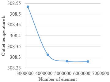
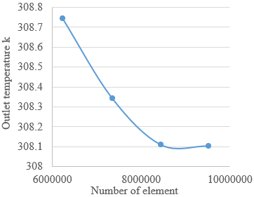
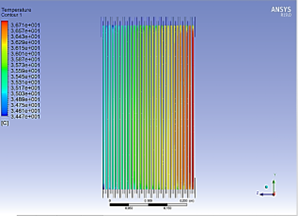
The simulation process requires the work of complex algorithms to solve the matrices contained in the domain, and therefore an accurate network must be made to solve the equations. And then work the reliability of the network for a solution to reach a stable state with the results. Because of the multiplicity of models that have been simulated, it is necessary to make more than one network and more than one network reliability. In the case where the number of plates is 10, the value of the net was 3187738 when the heat at the exit area reached 308.031 K. As for the second case, when the number of plates is 20 and the network reached 6342342, then the temperature was 308,279 K. Finally, in the case where the number of plates is 30, the value of the mesh was 9519873, where the exit temperature was 308.104 K as shown in Figures 3 and 4.
(a)
(b)
(c)
Figure 3. Mesh independency for: (a) 10 blades; (b) 20 blades; (c) 30 blades
(a)
(b)
(c)
Figure 4. (a) 10 blades mesh geometry; (b) 20 blades mesh geometry; (c) 30 blades mesh geometry
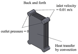
In order for the simulation process to take place, the appropriate settings and models for the solution must be developed to extract and compare the results. Where a constant entry velocity of 0.01 m/s was used at the entry area and a temperature of 313 K. As for the exit area, an exit pressure of 0pa was used. As for the remaining surfaces, convective heat transfer was applied to them, where the value of the heat transfer coefficient was 5 W/m.K and at an external temperature of 300 K as shown in Figure 5.
(a)
(b)
Figure 5. Boundary condition of: (a) direct flow; (b) back and forth flow
The condition for the state of movement is as per the following:
$\frac{\partial \rho}{\partial t}+\nabla \cdot(\rho \vec{v})=S_m$ (1)
In condition one it is on account of general movement, yet in condition 2 the condition is as a heading, or at least, it is in an extraordinary case, as it is given in the accompanying structure.
$\frac{\partial \rho}{\partial t}+\frac{\partial}{\partial x}\left(\rho v_x\right)+\frac{\partial}{\partial r}\left(\rho v_r\right)+\frac{\rho v_r}{r}=S_m$ (2)
where, x is the fundamental heading, r is the winding bearing, vx is the middle speed, and vr is the drawn-out speed. Protection of force in an inertial (non-speeding up).
$\frac{\partial}{\partial t}(\rho \vec{v})+\nabla \cdot(\rho \vec{v} \vec{v})=(-\nabla p+\nabla \cdot \overline{\bar{\tau}})+\rho \vec{g}+\vec{F}$ (3)
where, $p$ is the static strain, $\overline{\bar{\tau}}$ is the strain tensor (depicted under), and $p \vec{g}$ and $\vec{F}$ are the gravitational body power and outside body powers (for instance, that emerge from relationship with the scattered stage), autonomously. $\vec{F}$ similarly contains other model-subordinate source terms, for example, permeable media and client depicted sources. The strain tensor $\overline{\bar{\tau}}$ is given by:
$\bar{\tau}=\mu\left[\left(\nabla \vec{v}+\nabla \vec{v}^T\right)-\frac{2}{3} \nabla \cdot \vec{v} I\right]$ (4)
where, μ is the atomic consistency, I is the unit tensor, and the second term on the right hand side is the impact of volume expansion. For 2D axisymmetric calculations, the middle point and expanded power affirmation conditions are given by:
$\begin{aligned} \frac{\partial}{\partial t}\left(\rho v_x\right)+\frac{1}{r} \frac{\partial}{\partial x}\left(r \rho v_x v_x\right)+\frac{1}{r} \frac{\partial}{\partial r}\left(r \rho v_r v_x\right)= & -\frac{\partial p}{\partial x} \\ & +\frac{1}{r} \frac{\partial}{\partial x}\left[r \mu\left(2 \frac{\partial v_x}{\partial x}-\frac{2}{3}(\nabla \cdot \vec{v})\right)\right] \\ & +\frac{1}{r} \frac{\partial}{\partial r}\left[r \mu\left(\frac{\partial v_x}{\partial r}+\frac{\partial v_r}{\partial x}\right)\right]+F_x\end{aligned}$ (5)
and
$\begin{aligned} \frac{\partial}{\partial t}\left(\rho v_r\right)+\frac{1}{r} \frac{\partial}{\partial x}\left(r \rho v_x v_r\right)+\frac{1}{r} \frac{\partial}{\partial r}\left(r \rho v_r v_r\right)= & -\frac{\partial p}{\partial r} \\ & +\frac{1}{r} \frac{\partial}{\partial x}\left[r \mu\left(\frac{\partial v_r}{\partial x}+\frac{\partial v_x}{\partial r}\right)\right] \\ & +\frac{1}{r} \frac{\partial}{\partial r}\left[r \mu\left(2 \frac{\partial v_r}{\partial r}-\frac{2}{3}(\nabla \cdot \vec{v})\right)\right] \\ & -2 \mu_{r^r}^{v_r}+\frac{2}{3} \frac{\mu}{r}(\nabla \cdot \vec{v})+\rho \frac{v_r}{r}+F_r\end{aligned}$ (6)
where,
$\nabla \cdot \vec{v}=\frac{\partial v_x}{\partial x}+\frac{\partial v_r}{\partial r}+\frac{v_r}{r}$ (7)
The results obtained through the simulation program will be reviewed into two parts. The first part represents the heat exchanger with a direct direction and the change in the number of plates. As for the second part, it represents the heat exchanger with a reverse path and compare them with each other.
5.1 The effect of the number of plates on heat transfer
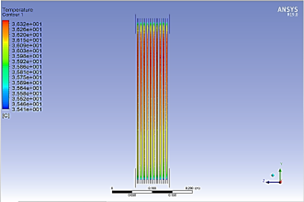
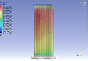
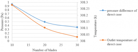
Increasing the number of plates in the plate heat exchanger increases the transfer area and thus increases the value of the transferred heat energy. Through Figure 6, and by changing the number of plates used, we notice an increase in the transfer of thermal energy, as in the case where the number of plates is 30, the best transfer of heat energy is compared to 20 and 10, where the exit temperature reached 308.104 K.
(a)
(b)
(c)
Figure 6. Temperature contour in: (a) 10 blades; (b) 20 blades; (c) 30 blades
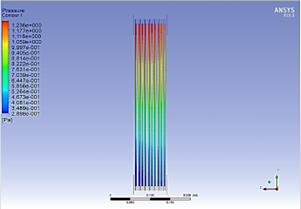
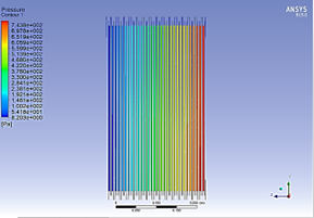
The basic principle of heat exchangers is the transfer of heat energy, but not at the expense of the pressure value. It is necessary to maintain the pressure difference between the entry and exit area of the diaper on the value of the flow transfer of the fluid. Through Figure 7 it is noted that the value of the pressure difference decreases with the increase in the number of plates used in the heat exchanger, and that Because the flow is direct, the water is allowed to flow easily through the distributed pipe, where the value of the pressure difference in the case in which the number of plates is 30 was 0.35 pa, which is a small and serious pressure difference value compared to the other cases.
(a)
(b)
(c)
Figure 7. Pressure contour in: (a) 10 blades; (b) 20 blades; (c) 30 blades
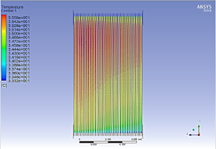
5.2 The effect of the direction of flow on the value of heat transfer
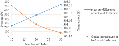
The process of changing the direction of flow and making it take a longer path of movement and surface contact for the transfer of heat energy is necessary in plate heat exchangers. Through Figure 8, the method of heat transfer between the two types of flow notes that in the case of the reverse direction, it is better, as the exit temperature reached when the number of plates is 30, and in the reverse direction it was 302.889 K, which is better compared to the direct direction. Where he notes the way the temperature changes in the direct direction is from top to bottom, but in the other flow the heat transfer is from right to left.
(a)
(b)
Figure 8. Temperature contour of: (a) direct flow; (b) back and forth flow
The increase in the pressure difference in the heat exchangers is undesirable and unsatisfactory. As the case in which the one-way runs have a small pressure difference. But with the good transfer of thermal energy in the direction of the reverse flow, but in the same place, it has a high and undesirable pressure difference, as the pressure difference reached 734 Pa, as in Figure 9.
(a)
(b)
Figure 9. Pressure contour of: (a) direct flow; (b) back and forth flow
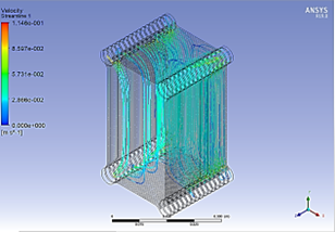
Figure 10 shows the method of fluid flow and its obstruction in movement for the two types of flow, as it is noted that the values of velocity in the flow in the opposite direction are relatively more compared to the direct direction. The reason for this is that the path of movement it passes through is narrow.
(a)
(b)
Figure 10. Velocity stream line of: (a) direct flow; (b)back and forth flow
Table 1 and Figure 11 show the different parameters that were reached in the different cases and the strength of the reverse direction in the transfer of thermal energy with the large pressure generated as a result of this movement.
Table 1. The output result of CFD
|
Number of blades |
Outlet temperature of direct case (K) |
Outlet temperature of back-and-forth case (K) |
Pressure difference of direct case (Pa) |
Pressure difference of back and forth case (Pa) |
|
10 |
308.279 |
303.250 |
0.9462 |
237.912 |
|
20 |
308.104 |
303.004 |
0.4956 |
487.171 |
|
30 |
308.031 |
302.889 |
0.35623 |
735.597 |
(a)
(b)
Figure 11. Temperature and pressure difference of: (a) direct flow; (b)back and forth flow
The results will be summarized as follows:
The authors would like to thank Al-Mustaqbal University College for the assistance in completing this work.
[1] Chtourou, S., Djemel, H., Kaffel, M., Baccar, M. (2021). Predicting the effect of the rib pitch on thermal performance factor of small channels plate heat exchangers fitted with Y and C shapes obstacles. SN Applied Sciences, 3: 1-28. https://doi.org/10.1007/s42452-021-04473-z
[2] Li, W.Z., Hrnjak, P. (2021). Single-phase flow distribution in plate heat exchangers: Experiments and models. International Institute of Refrigeratio, 126: 45-56. https://doi.org/10.1016/j.ijrefrig.2021.01.026
[3] Elmekawy, A.M.N., Ibrahim, A.A., Shahin, A.M., Al-Ali, S., Hassan, G.E. (2021). Performance enhancement for tube bank staggered configuration heat exchanger – CFD Study. Chemical Engineering and Processing: Process Intensification, 164, Article ID: 108392. https://doi.org/10.1016/j.cep.2021.108392
[4] Kim, B.R., Kim, M.S., An, S.K., Park, C.W. (2020). Design of welded chevron plate heat exchanger: Application of recuperator in LiBr-water absorption systems. Journal of Mechanical Science and Technology, 34: 4763-4771. https://doi.org/10.1007/s12206-020-1033-3
[5] Eldeeb, R., Aute, V., Radermacher, R. (2020). Pillow plate heat exchanger weld shape optimization using approximation and parallel parameterized CFD and non-uniform rational B-splines. International Institute of Refrigeration, 110: 121-131. https://doi.org/10.1016/j.ijrefrig.2019.10.024
[6] Gürel, B., Akkaya, V.R., Göltaş, M., Şen, C.N., Güler, O.V., Koşar, M.L., Keçebaş, A.(2020). Investigation on flow and heat transfer of compact brazed plate heat exchanger with lung pattern. Applied Thermal Engineering: 175, Article ID: 115309. https://doi.org/10.1016/j.applthermaleng.2020.115309
[7] Taufiq, A., Dhakar, P.S. (2020). CFD analysis of plate heat exchanger by using ansys. International Journal Research and Analytical Reviews, 7(3). https://doi.org/10.13140/RG.2.2.16507.95526
[8] Dietrich, A., Nowitzki, M., Van De Sand, R., Reiff-Stephan, J. (2020). Numerical simulation of condensing ammonia in plate heat exchangers using CFD. European Council for Modelling and Simulation, 34: 41-47. https://doi.org/10.7148/2020-0041
[9] Alzahran, S., Islam, M.S., Saha, S.C. (2019). A thermo-hydraulic characteristics investigation in corrugated plate heat exchanger. Energy Procedia, 160: 597-605. https://doi.org/10.1016/j.egypro.2019.02.211
[10] Chien, N.B., Jong-Taek, O., Asano, H., Tomiyama, Y. (2019). Investigation of experiment and simulation of a plate heat exchanger. Energy Procedia, 158: 5635-5640. https://doi.org/10.1016/j.egypro.2019.01.575
[11] Shirzad, M., Delavar, M.A., Ajarostaghi, S.S.M., Sedighi, K. (2019). Evaluation the effects of geometrical parameters on the performance of pillow plate heat exchanger. Chemical Engineering Research Design, 150: 74-83. https://doi.org/10.1016/j.cherd.2019.06.032
[12] Emani, S., Ramasamy, M., Shaari, K.Z. (2019). Discrete phase-CFD simulations of asphaltenes particles deposition from crude oil in shell and tube heat exchangers. Applied Thermal Engineering, 149: 105-118. https://doi.org/10.1016/j.applthermaleng.2018.12.008
[13] Khanlari, A., Sözen, A., Variyenli, H. (2019). Simulation and experimental analysis of heat transfer characteristics in the plate type heat exchangers using TiO2/water nanofluid. International Journal of Numerical Methods for Heat & Fluid Flow, 29: 1343-1362. https://doi.org/10.1108/HFF-05-2018-0191
[14] Della Torre, A., Montenegro, G., Onorati, A., Khadilkar, S., Icarelli, R. (2019). Multi-scale CFD modeling of plate heat exchangers including offset-strip fins and dimple-type turbulators for automotive applications. Energies, 12(15): 2965. https://doi.org/10.3390/en12152965
[15] Schaer, N., Odinot, J.M., Tang, K., Dufresne, M., Vazquez, J., Isenmann, G. (2018). Numerical study of a plate heat exchanger using CFD: Comparison of texture loss assessed by rheological measurements. Journal Food Process Engineering, 41: 1-5. https://doi.org/10.1111/jfpe.12889
[16] Bhattad, A., Sarkar, J., Ghosh, P. (2018). Discrete phase numerical model and experimental study of hybrid nanofluid heat transfer and pressure drop in plate heat exchanger. International Communications in Heat and Mass Transfer, 91: 262-273. https://doi.org/10.1016/j.icheatmasstransfer.2017.12.020
[17] Lazarevikj, M., Filkoski, R.V., Markov, Z. (2018). CFD analysis of heat transfer and fluid flow in plate heat exchanger with nanofluid. Conference in 3rd South East European Conference on Sustainable Development of Energy, Water and Environment Systems - SDEWES SEE, Novi Sad, Serbia.
[18] Mandic, D. (2020). CFD modeling of turbulence in channels of plate heat exchangers. Journal of Fluid Flow, Heat and Mass Transfer, 7: 46-57. https://doi.org/10.11159/jffhmt.2020.005
[19] Abed, A.M., Abed, I.A., Majdi, H.S., Al-Shamani, A.N., Sopian, K. (2016). A new optimization approach for shell and tube heat exchangers by using electromagnetism-like algorithm (EM). Heat Mass Transfer, 52: 2621-2634. https://doi.org/10.1007/s00231-016-1769-6
[20] Majdi, H.S., Alabdly, H.A., Hasan, B.O., Hathal, M.M. (2019). Oil fouling in double-pipe heat exchanger under liquid-liquid dispersion and the influence of copper oxide nanofluid. Heat Transfer—Asian Research, 48: 1963-1981. https://doi.org/10.1002/htj.21473
[21] Hasan, B.O., Majdi, H.S., Hathal, M.M. (2020). Study on oil fouling in a double pipe heat exchanger with mitigation by a surfactant. Heat Transfer, 49: 2645-2658. https://doi.org/10.1002/htj.21738
[22] Mahmoud, A. Mashkour, Hasan Shakir Majdi, Laith Jaafer Habeeb. (2021). Enhancement of forced convection heat transfer in tubes and heat exchangers using passive techniques: A review. Journal of Mechanical Engineering Research and Developments, 44(3): 208-218.
[23] Tarrad, A.H. (2021). Borehole thermal analysis for a closed loop vertical U-tube DX ground heat exchanger. Mathematical Modelling of Engineering Problems, 8(4): 501-509. https://doi.org/10.18280/mmep.080402
[24] Abbas, A.S., Mohammed, A.A. (2022). Augmentation of plate-fin heat exchanger performance with support of various types of fin configurations. Mathematical Modelling of Engineering Problems, 9(5): 1406-1414. https://doi.org/10.18280/mmep.090532