Ruwaida Al-Musawi*![]() | Sepanta Naimi
| Sepanta Naimi![]()
© 2023 IIETA. This article is published by IIETA and is licensed under the CC BY 4.0 license (http://creativecommons.org/licenses/by/4.0/).
OPEN ACCESS
In this research, a case study is explored and examined by choosing a construction project. The budget of this project is calculated and analyzed using two methods. A comparison between these two approaches is conducted in terms of performance, effort, accuracy, and cost of calculation. These two techniques are manual quantity surveying and numerical project take-off depending on BIM technology (REVIT software package). The quantity take-off of steel, concrete, and other vital architectural elements and structural building components was considered. The results of this work revealed that there are perfect agreements between the traditional cost-estimation method and the ANSYS numerical calculation associated with all construction elements and components, indicating that BIM technology can offer a reliable solution to determine the construction project cost with higher complexity and components. Furthermore, it was found that the use of REVIT software has cut a significant number of human errors that occurred during the estimation process and quantity take-off for the project cost. In addition, the results of the manual and numerical methods of cost calculation indicated that the REVIT software had saved much time and effort needed for engineers to estimate the budget related to this challenging case study that represents a hospital building with various structural components.
cost estimation, BIM technology, construction project, quantity surveying, REVIT software, budget management
Due to the rising number of small-, medium-, and large-scale construction projects worldwide, and because of the increasing rates of projects’ complexity, the estimation process of the budget related to the construction project has become more complicated, effort, and time-consuming, and may contribute to a larger number of human errors [1-4]. The motivation of this research is reflected in the critical benefits, and substantial contributions of modern constriction techniques like Building Information Modeling (BIM) in helping civil engineers, quantity surveyors, designers, and planners calculate the volume of construction materials with higher degrees of accuracy, less human errors, less effort, and very low amount of time and cost required to make the materials quantity take-off. BIM technology is vital because conventional approaches to materials quantity take-off consume much time, effort, and budget to make the quantity take-off. Furthermore, traditional quantity take-off techniques implemented by engineers may contribute to several numbers of errors. Thus, these conventional methods may not be effective, reliable, or more precise in evaluating the required construction materials.
The construction projects’ activities and parameters associated with each building task have been growing in the last decades, leading to higher challenges and difficulties for quantity surveyors to calculate the cost of each project as the complexity of these projects is remarkable. Additionally, if the calculation process relies on human efforts, the cost assessment will contribute to various errors and less precision, and it will consume much time [5-7]. In this context, designers, planners, and scholars have been working through decades of Research and Development (R&D) to develop BIM technology and REVIT software package that can be capable of providing state-of-the-art cost-evaluation techniques by which these problems can be alleviated and resolved. Besides, planners and project managers improved the BIM software potential to enable flexible and practical evaluation of the budget of large-scale construction projects characterized by a significant level of complexity and linked to a considerable number of tasks and activities. In this project, the BIM technology is implemented to calculate the budget of a construction project relying on the REVIT software, one of the novel software programs which can implement BIM principles in the project’s cost-evaluation process. Shaqour [8] executed research examining the beneficial impacts and critical role of BIM technology implementation on the construction industry in Egypt. They applied quantitative, analytical, and descriptive methods to achieve the study goal. They reported that the Egyptian construction industry faces some challenges mirrored by losses in construction materials, budget, and execution time. The quantitative, analytical, and descriptive analysis (which covered 106 Egyptian experts in BIM technology) revealed that applying BIM technology is greatly beneficial for the Egyptian construction sector and can significantly improve the project management procedure throughout the project’s lifetime. Charef et al. [9] carried out research exploring the major advantages and key characteristics of BIM technology in the construction industry. They selected a case study (presenting a veterinary clinic) using the REVIT/ Auto-Desk software package. They implemented 5D BIM modelling through which a three-dimensional configuration of the veterinary clinic was executed, besides cost and time estimation. Their BIM analysis of their case study revealed that applying BIM principles with 5D contributed to significant accuracy in evaluating the budget and schedule of the veterinary clinic. Also, it was found that using BIM technology can replace manual calculation approaches for construction projects’ time and cost, saving much effort and reducing human errors. In addition, results indicated that the design process could be effectively automated, making BIM modelling greatly beneficial for construction project performance. Banihashemi et al. [10] conducted an analysis examining the critical role of BIM technology modelling in facilitating construction projects’ execution and improving performance. They integrated machine learning (ML) principles into the BIM system. They also developed a prototype to train the ML algorithms in estimating the construction project’s cost with fewer errors. The software that operated these ML algorithms with 5D-BIM modelling was MATLAB software. Their numerical analysis revealed that using 5D modelling of BIM technology and integrating ML algorithms into the estimation process contributed to significant improvements in evaluating the construction project’s budget. Also, numerical results confirmed that BIM technology implementation with ML algorithms provided higher accuracy and eliminated human errors. Sepasgozar et al. [2] carried out research investigating the critical role of BIM technology in evaluating the construction project’s cost. They applied critical content and systematic reviews through which BIM technology’s contribution and substantial role in estimating construction projects cost were identified. Their critical literature analysis revealed that implementing BIM technology, particularly 5D modelling, has several significant advantages to the construction project. Results indicated that 5D modelling helps engineers and surveyors estimate the construction project budget with a higher accuracy degree and minimizes human errors, as manual calculation methods can be avoided. Lin [11] carried out a study identifying major BIM technology roles and critical contributions to the construction project in estimating safety index and productivity. Lin depended on a case study analysis of Singapore’s safety system and intelligent productivity framework. Also, they followed a comprehensive literature review. Several recent articles and academic publications addressed the importance of critical BIM technology significance in accomplishing higher safety standards and productivity of construction projects. The comprehensive literature analysis revealed that BIM technology plays a beneficial role and positively impacts the construction industry in achieving considerable safety standards. Also, BIM technology can improve construction projects’ productivity rate and manage their resources. Mahamood and Fathi [12] executed an analysis examining the important role of BIM principles in managing and designing a seismic building associated with Malaysian governmental construction projects. They depended on a semi-structured qualitative approach through which interviews were conducted with construction industry experts and stakeholders from the Malaysian government to address the critical role of BIM technology in seismic building design. Their qualitative research approach revealed that BIM technology plays a significant role in managing, designing, and monitoring buildings with earthquakes and seismic impacts. Also, BIM modelling can help control project activities and improve construction projects’ performance. Quoc et al. [13] performed research investigating the significance of BIM technology adoption and implementation in improving the performance of several construction projects. They applied a cross-sectional descriptive quantitative study through which questionnaire surveys were applied, covering 159 experts in the BIM technology used in the construction sector. Their cross-sectional research findings indicated that implementing BIM technology in the construction industry provides advantageous impacts and positive effects for facility managers, contractors, owners, structural and architectural engineers, and other construction stakeholders. Also, the results revealed that BIM technology contributed to several significant improvements in the design drawings’ quality. In addition, BIM technology offered a remarkable reduction in the changes/ conflicts/ claims throughout the project execution. Moreover, BIM implementation helped offer flexible planning and resource management and mobilization. Also, utilizing BIM principles contributed to a considerable reduction in human errors and time savings in estimating the construction project’s cost and time. Further, Heigermoser et al. [14], Alizadehsalehi et al. [15], Arif et al. [16], Toan et al. [17], Jia [18], Xu et al. [19], Adekunle et al. [20] carried out research examining the critical benefits of BIM technology and REVIT software in managing construction. They found that using the REVIT software and BIM principles could help increase the performance of project execution, accuracy in making quantity take-off, and reduce human errors.
The structure of this work consists of some topics that will be covered in the following sections. For instance, section two will discuss the materials, methods, and significant research approaches adopted and executed to carry out the primary data collection of this work. Following this section, section three describes the preliminary research results obtained from the research approaches implemented by the researcher. Section four illustrates the research discussions by relating the finding of this work to other researchers. Section five depicts the conclusions and a summary of the main research outcomes of this study.
2.1 Case study description
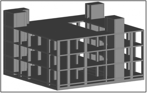
Figure 1. The case study: Hospital building
The case study consists of a hospital building comprising four floors (ground floor, first floor, second floor, and roof). The major hospital building’s rooms include the main entrance, optical, pharmacy, secondary entrance, lobby, health gas system, electrical board room, main reception, waiting, special waiting, doctor room, general examination, special examination, cafeteria, prayer, garden, special corridor, nursing, patient room, locker, change clothes, doctors break, patient sterilization room, medical sterilization room, sterile corridor, operations hall, Lasik operation, kitchenette, UBS room, and elevator room (see Table 1). Figure 1 presents a concrete-based model of the hospital building.
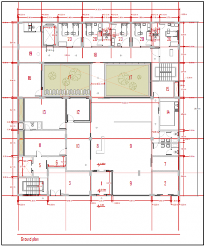
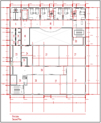
In addition, Figures 2, 3, and 4 represent the shop drawing related to the floor plan of the ground, first, second, and roof floors.
Figure 2. The ground floor of the hospital construction project
Table 1. Some details on the hospital construction building
|
# |
Floor |
Area (m2) |
Parts of the floor, use |
|
1 |
Ground floor |
600 |
The main entrance, Optical, Pharmacy, Secondary entrance, Lobby, Healthy gas system, Electrical Room, Main Reception, Waiting, Special Waiting, Doctor room, General Examination, Special Examination, Cafeteria, Prayer, Laboratory, Garden, Special corridor, Nursing, Inpatient room. |
|
2 |
First floor |
600 |
Locker, Change Clothes, Doctors Break, Patient sterilization room, Medical sterilization room, Sterile corridor, Operations hall, Lasik Operation, Kitchenette, UBS Room. |
|
3 |
Second floor |
600 |
Locker, Change Clothes, Doctors Break, Patient sterilization room, Medical sterilization room, Sterile corridor, Operations hall, Lasik Operation, Kitchenette, UBS Room. |
|
4 |
Roof floor |
41.65 |
Elevator rooms. |
Figure 3. The first and second floors plan of the hospital construction project
Figure 4. The roof plan of the hospital construction project
2.2 Manual quantity surveying procedure
2.2.1 Concrete evaluation
Table 2 presents the process of calculating the cut.
Table 2. Calculating the cut manually
|
Cut (m3) = Excavation area × Excavation depth |
Value |
|
Cut = 24.2 × 25.2 × 2.00 |
1,219.73 m3 |
Table 3 presents the process of calculating the blinding volume.
Table 3. Calculating the blinding volume manually
|
Blinding (m3) (100 mm depth) |
Value |
|
Volume = (L1×L2×H) – opening volume |
54.40 m3 |
|
Volume = (24.2×25.2×0.1) – (4.8×13.7×0.1) |
Table 4 presents the process of calculating the boulder volume.
Table 4. Calculating the boulder volume manually
|
Boulder Volume (m3) (200 mm depth) |
Value |
|
Volume = (L1×L2×H) – opening volume |
108.82 m3 |
|
Volume = (24.2×25.2×0.2) – (4.8×13.7×0.2) |
L1, L2, and H in Table 4 depict the length, width, and height of the cube related to the concrete boulder, respectively.
Table 5. Calculating the sub-base volume manually
|
Sub-base Volume (m3) (400 mm depth) |
Value |
|
Volume = (L1×L2×H) – opening volume |
217.64 m3 |
|
Volume = (24.2×25.2×0.4) – (4.8×13.7×0.4) |
Table 5 represents the process of calculating the boulder volume.
Table 6. Calculating the lean concrete volume manually
|
Lean concrete Volume (m3) (100 mm depth) |
Value |
|
Volume = (L1×L2×H) – opening volume |
54.40 m3 |
|
Volume = (24.2×25.2×0.1) – (4.8×13.7×0.1) |
Table 6 describes the process of calculating the lean concrete volume.
Table 7. Calculating the bitumen volume manually
|
Bitumen Volume (m3) (8 mm depth) |
Value |
|
Volume = (L1×L2×H) – opening volume |
4.35 m3 |
|
Volume = (24.2×25.2*0.008) – (4.8×13.7×0.008) |
Table 7 illustrates the process of calculating the bitumen volume.
Table 8. Calculating the reinforced concrete volume for the raft foundation
|
Item |
Slab Length (m) |
Slab Width (m) |
Depth (m) |
Opening Volume (Cuboid Hole) (m3) |
Value |
|
Raft Foundation |
24.00 |
25.00 |
0.65 |
(4.8×13.7×0.65) = 42.74 |
347m3 |
Table 8 illustrates the calculation procedure for the reinforced concrete volume for the raft foundation.
The process of calculation conducted in Table 8 can be expressed in the following formula:
Reinforced Concrete (m3) = (length × width × depth of foundation) – opening volume (1)
Hence, the reinforced concrete volume equals:
24 × 25 × 0.65 - (4.8 × 13.7 × 0.65) = 347.3 m3.
Table 9. Calculating the reinforced concrete columns’ volume
|
Concrete Columns Volume = Length × Width × Height |
|||||
|
Total height from raft footing to second floor = (5 + 4 + 4 + 0.65) m, = 13.65 m Total height from raft footing to second floor = (5 + 4 + 4 + 4+ 0.65) m, = 17.65 m, without Slabs height |
|||||
|
Item |
length |
width |
height |
# |
Total |
|
C1 |
0.75 |
0.30 |
13.65 |
10 |
30.72 |
|
C1 |
0.75 |
0.30 |
17.65 |
1 |
3.97 |
|
C2 |
0.75 |
0.30 |
17.65 |
1 |
3.97 |
|
C2 |
0.75 |
0.30 |
13.65 |
10 |
30.72 |
|
C3 |
0.75 |
0.30 |
17.65 |
1 |
3.97 |
|
C3 |
0.75 |
0.30 |
13.65 |
3 |
9.21 |
|
C4 |
0.75 |
0.35 |
13.65 |
1 |
3.58 |
|
C5 |
0.45 |
0.45 |
13.65 |
4 |
11.06 |
|
C6 |
0.70 |
0.25 |
13.65 |
4 |
9.56 |
|
Total columns reinforced concrete |
106.8 m3 |
||||
Table 9 illustrates the calculation for the reinforced concrete columns’ volume.
Table 10. Calculating the reinforced concrete walls’ volume
|
Total height from raft footing to second floor = (5 + 4 + 4 +4+ 0.65) m = 17.65 m, without Slabs height |
||||
|
Reinforced concrete walls = Length × Width × Height |
||||
|
Item |
Length (m) |
Width (m) |
Height (m) |
Total (m3) |
|
SW1 & SW2 |
8.10 |
0.30 |
17.65 |
42.89 |
|
Elevator 1 & 2 |
18.8 |
0.25 |
17.65 |
82.96 |
|
Total Walls reinforced Concrete Volume |
125.85 m3 |
|||
Table 10 describes the estimation of the volume of the reinforced concrete walls.
Table 11. Calculating the reinforced concrete beams’ volume
|
Beams Concrete = Height × Width × Length |
|||||
|
Item |
Length (m) |
Width (m) |
Height (m) |
# |
Total (m3) |
|
B1 |
98.00 |
0.35 |
0.70 |
3 |
72.03 |
|
B2 |
51.68 |
0.70 |
0.32 |
3 |
34.73 |
|
B3 |
42.80 |
0.8 |
0.32 |
3 |
32.87 |
|
B4 |
16.3 |
0.5 |
0.32 |
3 |
7.82 |
|
B6 |
17.43 |
0.35 |
0.7 |
3 |
12.81 |
|
B7 |
26.56 |
0.35 |
0.8 |
3 |
22.31 |
|
Total of beams reinforced concrete |
182.6 m3 |
||||
Table 11 describes the estimation of the volume of the reinforced concrete beams.
Table 12. Calculating the volume of the hollow/waffle blocks
|
Hollow/Waffle Blocks Volume = Number of blocks × Volume of one block × Number of floors |
Value |
|
volume= #Blocks×0.0192 |
140.04 m3 |
|
Volume = 2431 × 0.0192 × 3 |
Table 12 describes the estimation of the volume of the hollow/waffle blocks.
Table 13 describes the estimation of the reinforced concrete slabs’ volume.
Table 14 describes the estimation of the total reinforced concrete volume.
Table 13. Calculating reinforced concrete slabs’ volume
|
Slabs reinforced Concrete Volume = (Total Volume of one slab – (Hollow Blocks Volume + Beams reinforced Concrete Volume + opening volume)) × Number of floors |
||||||
|
Item |
Floor total volume one floor (m3) |
Floor opening one floor (m3) |
Beams concrete one floor (m3) |
Hollow blocks volume one floor (m3) |
# |
Total (m3) |
|
Slab on grade 1 |
34.38 m2 × 0.18 m = 6.19 |
--- |
----- |
---- |
1 |
6.19 |
|
Slab on grade 2 |
492.77 m2 × 0.36 m = 177.40 |
---- |
---- |
---- |
1 |
177.40 |
|
GF, 1st, 2nd floor |
600 m2 × 0.32 m = 192 |
96.37 m2 × 0.32 m = 30.84 |
182.57 / 3 = 60.86 |
140.04 /3 = 46.68 |
3 |
160.86 |
|
Top of roof Solid slab |
41.65 m2 × 0.15 m = 6.25 |
---- |
---- |
---- |
1 |
6.25 |
|
Steps |
66 steps × 0.5 × 0.3 m × 0.165 m × 1 m = 1.63 |
---- |
---- |
0.36 |
1 |
1.63 |
|
Stair ladders |
34 m × 1 m × 0.3 m = 10.2 |
---- |
---- |
15.84 |
1 |
10.2 |
|
Total of reinforced concrete slabs |
362.53 |
|||||
Table 14. Calculating total reinforced concrete volume
|
Raft foundation |
Columns |
Walls |
Beams |
Slabs |
|
347.26 m3 |
106.76 m3 |
125.85 m3 |
182.57 m3 |
362.53 m3 |
|
Total = 1,124.97 m3 |
||||
2.2.2 Steel evaluation
According to International Building Code (IBC) and National Concrete Masonry Association (NCMA), the recommended steel reinforcement ratio in concrete amounts between 0.5% and 4% [21]. Furthermore, the building code ACI 318-19 determines the minimum longitudinal reinforcement ratio for the column with a ratio of 0.01 times the concrete column’s gross area. The reinforcement steel is computed using the formula:
Reinforcement Steel (kg)=Bar weight (kg/m)×Length (m) × No. of bars, (2)
where, bar weight can be estimated by the expression:
Bar Weight $(\mathrm{kg} / \mathrm{m})=\operatorname{Diameter}^2\left(\mathrm{~mm}^2\right) / 162$, (3)
Table 15. The classification of steel diameters and weight used in this project
|
Dia. used in this project |
Weight /m = Dia. (mm2)/162 |
Total weight (kg/m) |
|
25 mm |
(25)2/162 |
3.8 |
|
20 mm |
(20)2/162 |
2.47 |
|
18 mm |
(18)2/162 |
2.00 |
|
16 mm |
(16)2/162 |
1.580 |
|
14 mm |
(14)2/162 |
1.21 |
|
12 mm |
(12)2/162 |
0.89 |
|
10 mm |
(10)2/162 |
0.62 |
The classification of steel diameters and weight used in this project are explained in Table 15.
Table 16. The overall steel calculation manually
|
Part |
Weight (kg) |
|
Raft foundation steel reinforcement |
25950.88 |
|
Columns steel reinforcement |
39699.8 |
|
Walls steel reinforcement |
24534.7 |
|
Slabs steel reinforcement |
41504.9 |
|
Beams steel reinforcement |
31335.20 |
|
Total steel reinforcement in this project (kg) |
163025.5 |
|
Total = 163.0255 Ton |
|
The overall steel calculation is explained in Table 16.
2.2.3 Architectural elements evaluation
Table 17. The quantity calculation of external blocks manually
|
Blocks Number = ((L×H) – (opening area))×(1.00)/(Area of Blocks) |
|||||
|
Floor |
Length (m) |
Height (m) |
Opening area (m2) |
Area of Block (m2) |
Total |
|
GR |
74.86 |
5.00 |
79.25 |
0.08 |
3688 |
|
1st |
74.86 |
4.00 |
---- |
0.08 |
3743 |
|
2nd |
74.86 |
4.00 |
---- |
0.08 |
3743 |
|
Roof |
74.86 |
1.00 |
---- |
0.08 |
936 |
|
Total blocks |
12110 |
||||
|
968.8 m2 |
|||||
The quantity calculation of external blocks is explained in Table 17.
Table 18. The quantity calculation of the external glass wall manually
|
Floor |
Length (m) |
Height (m) |
Total area (m2) |
|
GR |
15.01 |
5.00 |
75.05 |
|
1st |
----- |
---- |
----- |
|
2nd |
----- |
---- |
----- |
|
Roof |
----- |
---- |
----- |
|
Total Area (m2) |
75.05 m2 |
||
The quantity calculation of the external glass wall is illustrated in Table 18.
Table 19. The quantity calculation of external plaster manually
|
Plaster Area = ((L*H) – (Opening area)) |
||||
|
Floor |
Length (m) |
Height (m) |
Opening area (m2) |
Total area (m2) |
|
GR/ 1st / 2nd and Roof |
98.00 |
15.79 |
79.25 |
1468.17 |
|
Plaster Area (m2) |
1468.17 m2 |
|||
The quantity calculation of external plaster is illustrated in Table 19.
Table 20. The quantity calculation of external stone manually
|
Stones Area = ((L*H) – (Opening area)) |
||||
|
Floor |
Length (m) |
Height (m) |
Opening area (m2) |
Total area (m2) |
|
GR/ 1st / 2nd and Roof |
98.00 |
15.79 |
79.25 |
1468.17 |
|
Stones area m2 |
1468.17 m2 |
|||
The quantity calculation of external stone is illustrated in Table 20.
Table 21. The quantity calculation of internal blocks manually
|
Blocks Number = ((L*H) – (opening area))×(1.0)/Area of Blocks |
|||||
|
Floor |
Length (m) |
Height (m) |
Opening Area (m2) |
Area of Block (m2) |
Total |
|
GR |
114.25 |
5.00 |
46.50 |
0.08 |
6560 |
|
1st |
162.56 |
4.00 |
68.5 |
0.08 |
7272 |
|
2nd |
162.56 |
4.00 |
68.5 |
0.08 |
7272 |
|
Roof |
---- |
---- |
---- |
---- |
---- |
|
Total Blocks |
21,104 |
||||
|
1688.32 m2 |
|||||
The quantity calculation of internal blocks is illustrated in Table 21.
Table 22. The quantity calculation of the internal glass wall manually
|
Floor |
Length (m) |
Height (m) |
Total area (m2) |
|
GR |
44.35 |
5.00 |
221.75 |
|
1st |
27.32 |
4.00 |
109.28 |
|
2nd |
27.32 |
4.00 |
109.28 |
|
Roof |
---- |
---- |
---- |
|
Total Area (m2) |
440.31 m2 |
||
The quantity calculation of the internal glass wall is depicted in Table 22.
Table 23. The quantity calculation of the internal plaster and paint manually
|
Internal plaster and paint = ((L*H) – (opening area)) |
||||
|
Floor |
Length (m) |
Height (m) |
Opening area (m2) |
Total area (m2) |
|
GR |
324.72 |
5.00 |
168.58 |
1455.02 |
|
1st |
433.12 |
4.00 |
154.49 |
1577.99 |
|
2nd |
162.56 |
4.00 |
154.49 |
1577.99 |
|
Roof |
---- |
---- |
---- |
---- |
|
Total Area |
4611 m2 |
|||
The quantity calculation of the internal plaster and paint is depicted in Table 23.
Table 24. The quantity calculation of the internal tiles manually
|
Floor |
Area |
|
GR |
407.04 |
|
1st |
462.13 |
|
2nd |
462.13 |
|
Roof |
492.47 |
|
Total area of tiles |
1823.77 m2 |
The quantity calculation of the internal tiles is depicted in Table 24.
2.3 Revit quantity surveying procedure
Table 25. The total concrete quantity calculated using the REVIT software
|
Raft foundation |
Columns |
Walls |
Beams |
Slabs |
|
349.59 m3 |
106.37 m3 |
126.48 m3 |
183.79 m3 |
364.01 m3 |
|
Total = 1130.24 m3 |
||||
The total concrete quantity calculated using the REVIT software is presented in Table 25.
Table 26. The total steel reinforcement estimated using the REVIT software
|
Part |
Weight (kg) |
|
Raft foundation steel reinforcement |
26566.05 |
|
Columns steel reinforcement |
40123.40 |
|
Walls steel reinforcement |
24936.53 |
|
Slabs steel reinforcement |
40523.30 |
|
Beams steel reinforcement |
30671.84 |
|
Total steel reinforcement in this project (kg) |
162821.12 |
|
162.82112 Ton |
|
The total steel reinforcement estimated using the REVIT software is presented in Table 26.
The total quantity of the project’s architectural components is computed using REVIT in Table 27.
Also, the internal tiles area was evaluated using the REVIT software, which is described in Table 28.
Table 27. The total quantity of the project’s architectural components using the REVIT software
|
Category |
Quantity |
|
External Blocks |
1036.48 m2 |
|
External Glass Wall Area |
72.93 m2 |
|
External Plaster |
1570.68 m2 |
|
External Stones |
1690.59 m2 |
|
Internal Blocks |
1868.96 m2 |
|
Internal Glass Wall Area |
494.69 m2 |
|
Internal Plaster and Paint |
4869.58 m2 |
Table 28. The quantity survey of the project’s internal tiles using the REVIT software
|
Floor |
Area |
|
GR |
413.36 |
|
1st |
473.29 |
|
2rd |
473.29 |
|
Roof |
513.97 |
|
Total area of tiles (m2) |
1873.91 m2 |
Based on the manual and numerical calculation processes of the construction project cost of this case study (hospital building), a comparison between the manual cost estimation approach and the REVIT software computation related to concrete and steel quantity take-off can be presented in Table 29.
Table 29. A comparison between the manual cost estimation approach and the REVIT software computation related to concrete and steel quantity take-off
|
Comparison |
Manual results |
REVIT results |
Error percent |
|
|
Concrete (m3) |
Blinding |
54.40 |
55.12 |
0.51% |
|
Raft concrete |
347.26 |
349.59 |
0.67% |
|
|
Slabs concrete |
362.53 |
364.01 |
0.41% |
|
|
Columns concrete |
106.76 |
106.37 |
0.37% |
|
|
Beams concrete |
182.57 |
183.79 |
0.67% |
|
|
Walls |
125.85 |
126.48 |
0.50% |
|
|
Steel (kg) |
Raft steel |
25950.88 |
26566.05 |
2.37% |
|
Slabs steel |
41504.90 |
40523.3 |
2.37% |
|
|
Columns steel |
39699.80 |
40123.4 |
1.07% |
|
|
Beams steel |
31335.20 |
30671.84 |
2.12% |
|
|
Walls steel |
24534.70 |
24936.53 |
1.64% |
|
Table 30. A comparison between the manual cost estimation technique and the REVIT software computation process related to architectural elements quantity take-off
|
Comparison |
Manual results |
Revit results |
|
Cut (m3) |
1219.73 |
1222.58 |
|
External Blocks (m2) |
968.8 |
1036.48 |
|
Internal Blocks (m2) |
1688.32 |
1868.96 |
|
External plaster (m2) |
1468.17 |
1570.68 |
|
Internal plaster and paint (m2) |
4611 |
4869.58 |
|
Stones (m2) |
1468.17 |
1690.59 |
|
Floor Tiles (m2) |
1823.77 |
1873.91 |
|
Internal Glass (m2) |
440.31 |
494.69 |
|
External Glass (m2) |
75.05 |
72.93 |
Also, another comparison between the manual cost estimation technique and the REVIT software computation process related to architectural elements quantity take-off can be presented in Table 30.
It can be inferred from the two tables that there are excellent agreements between the conventional cost-estimation method and the ANSYS numerical calculation associated with all construction elements and components, indicating that BIM technology can offer a reliable solution to determine the construction project cost with higher complexity and components. In addition, the use of REVIT software has cut a significant number of human errors that occurred during the estimation process and quantity take-off for the project cost. Furthermore, the REVIT software has saved much time and effort needed for engineers to estimate the budget related to this challenging case study that represents a hospital building with various structural components.
This research revealed that there are excellent agreements between the conventional cost-estimation method and the ANSYS numerical calculation associated with estimating the quantity of reinforcement steel, reinforcement concrete, and architectural elements. These results indicate that employing BIM technology is beneficial in providing a reliable solution to locate the construction project cost with higher levels of complexity and components. The results also indicated that using REVIT software had reduced a significant number of human errors throughout the quantity take-off of the project’s cost. The research findings also confirmed that the REVIT software could minimize much effort and time required by engineers to assess the budget related to challenging construction projects with higher complexity and components, like this case study. The results of this work are consistent with the research findings of [1-4], who stated that BIM technology and the REVIT software tool could minimize much of human errors and achieve a higher degree of precision. Also, these results are consistent with the findings of [5-7], who reported that the REVIT program could save considerable effort and time that would be significantly consumed by engineers to estimate the construction project cost. Also, the results of this study are compatible with [8-10], who analyzed the critical role of the BIM technology and REVIT software in estimating project costs and found that using the REVIT program can significantly cut effort, time, and cost required to calculate the construction projects costs that have higher complexity. Also, they found that employing BIM technology could enhance cost-calculation accuracy.
In this study, a case study is explored and examined, representing a construction project of a hospital building. The budget of this building is calculated and analyzed using two techniques. A comparison between these two approaches is conducted according to performance, effort, accuracy, and cost of calculation. These two approaches include manual quantity surveying and numerical project take-off, which depends on BIM technology using the REVIT software package. The quantity take-off of steel, concrete, and other vital architectural elements and structural building components was considered. The results of this work revealed the following aspects:
1- There are excellent agreements between the conventional cost-estimation method and the ANSYS numerical calculation associated with all construction elements and components, indicating that BIM technology can offer a reliable solution to determine the construction project cost with higher complexity and components.
2- The use of REVIT software has cut a significant number of human errors that occurred during the estimation process and quantity take-off for the project cost.
3- The REVIT software has saved much time and effort needed for engineers to estimate the budget related to this challenging case study that represents a hospital building with various structural components.
[1] San Cristóbal, J.R., Carral, L., Diaz, E., Fraguela, J.A., Iglesias, G. (2018). Complexity and project management: A general overview. Complexity, 2018: 4891286. https://doi.org/10.1155/2018/4891286
[2] Sepasgozar, S.M., Costin, A.M., Karimi, R., Shirowzhan, S., Abbasian, E., Li, J. (2022). BIM and digital tools for state-of-the-art construction cost management. Buildings, 12(4): 396. https://doi.org/10.3390/buildings12040396
[3] Villaschi, F.S., Carvalho, J.P., Bragança, L. (2022). BIM-based method for the verification of building code compliance. Applied System Innovation, 5(4): 64. https://doi.org/10.3390/asi5040064
[4] Zhan, Z., Tang, Y., Wang, C., Yap, J.B.H., Lim, Y.S. (2022). System dynamics outlook on BIM and lean interaction in construction quantity surveying. Iranian Journal of Science and Technology, Transactions of Civil Engineering, 46: 3947-3962. https://doi.org/10.1007/s40996-022-00833-w
[5] Moragane, H.P.M.N.L.B., Perera, B.A.K.S., Palihakkara, A.D. (2022). Application of computer vision for construction progress monitoring. In Proceedings the 10th World Construction Symposium, p. 126. https://doi.org/10.31705/WCS.2022.11
[6] Nguyen, T.Q., Lou, E.C., Nguyen, B.N. (2022). A theoretical BIM-based framework for quantity take-off to facilitate progress payments: the case of high-rise building projects in Vietnam. International Journal of Building Pathology and Adaptation. https://doi.org/10.1108/IJBPA-10-2021-0139
[7] Wu, Z., Ma, G. (2022). Automatic generation of BIM-based construction schedule: Combining an ontology constraint rule and a genetic algorithm. Engineering, Construction and Architectural Management. https://doi.org/10.1108/ECAM-12-2021-1105
[8] Shaqour, E.N. (2022). The role of implementing BIM applications in enhancing project management knowledge areas in Egypt. Ain Shams Engineering Journal, 13(1): 101509. https://doi.org/10.1016/j.asej.2021.05.023
[9] Charef, R., Alaka, H., Emmitt, S. (2018). Beyond the third dimension of BIM: A systematic review of literature and assessment of professional views. Journal of Building Engineering, 19: 242-257. https://doi.org/10.1016/j.jobe.2018.04.028
[10] Banihashemi, S., Khalili, S., Sheikhkhoshkar, M., Fazeli, A. (2022). Machine learning-integrated 5D BIM informatics: building materials costs data classification and prototype development. Innovative Infrastructure Solutions, 7(3): 1-25. https://doi.org/10.1007/s41062-022-00822-y
[11] Lin, E.T.A. (2022). An intelligent system for determining productivity and safety index using building information modelling: A case study of IPASS in Singapore. In Research Companion to Building Information Modelling. Edward Elgar Publishing: 415-435. https://doi.org/10.4337/9781839105524.00031
[12] Mahamood, S.Z.H., Fathi, M.S. (2022). Seismic building design work process using building information modelling (BIM) technology for Malaysian Government projects. International Journal of Disaster Resilience in the Built Environment, 13(2): 211-232. https://doi.org/10.1108/IJDRBE-10-2021-0135
[13] Quoc, T.N., Van, T.N., Ngoc, D.T., Xuan, A.P. (2022). Adoption of building information modelling in the construction project life cycle: Benefits for stakeholders. Architecture and Engineering, 7(1): 56-71. https://doi.org/10.23968/2500-0055-2022-7-1-56-71
[14] Heigermoser, D., de Soto, B.G., Abbott, E.L.S., Chua, D.K.H. (2019). BIM-based last planner system tool for improving construction project management. Automation in Construction, 104: 246-254. https://doi.org/10.1016/j.autcon.2019.03.019
[15] Alizadehsalehi, S., Hadavi, A., Huang, J.C. (2020). From BIM to extended reality in AEC industry. Automation in Construction, 116: 103254. https://doi.org/10.1016/j.autcon.2020.103254
[16] Arif, M.S., Nasihien, R.D., Sutowijoyo, H. (2021). BIM implementation in mall laves project construction Surabaya. International Journal of Engineering, Science and Information Technology, 1(2): 13-15. https://doi.org/10.52088/ijesty.v1i2.49
[17] Toan, N.Q., Anh, P.X., Tam, N.V. (2023). Trends in BIM tools adoption in construction project implementation: A case study in Vietnam. In Proceedings of FORM 2022, pp. 9-19. https://doi.org/10.1007/978-3-031-10853-2_2
[18] Jia, Y. (2021). Application analysis of BIM technology in project management. In 2021 International Conference on Intelligent Transportation, Big Data & Smart City (ICITBS), pp. 55-58. https://10.1109/ICITBS53129.2021.00022
[19] Xu, J., Li, B.K., Luo, S.M. (2018). Practice and exploration on teaching reform of engineering project management course in universities based on BIM simulation technology. EURASIA Journal of Mathematics, Science and Technology Education, 14(5): 1827-1835. https://doi.org/10.29333/ejmste/85417
[20] Adekunle, S.A., Aigbavboa, C.O., Ejohwomu, O.A. (2022). Understanding the BIM actor role: A study of employer and employee preference and availability in the construction industry. Engineering, Construction and Architectural Management. https://doi.org/10.1108/ECAM-08-2021-0714
[21] National Concrete Masonry Association (NCMA). (2022). TEK 12-04D, Steel Reinforcement for Concrete Masonry. Available at: https://ncma.org/resource/steel-reinforcement-for-concrete-masonry/, accessed on November 2, 2022.