Dandun Mahesa Prabowoputra![]() | Aditya Rio Prabowo*
| Aditya Rio Prabowo*![]() | Haris Nubli
| Haris Nubli![]() | Catur Harsito
| Catur Harsito![]() | Ubaidillah
| Ubaidillah![]() | Didik Djoko Susilo
| Didik Djoko Susilo![]() | Wibowo
| Wibowo![]() | Bhre Wangsa Lenggana
| Bhre Wangsa Lenggana![]()
© 2023 IIETA. This article is published by IIETA and is licensed under the CC BY 4.0 license (http://creativecommons.org/licenses/by/4.0/).
OPEN ACCESS
Hydro energy installations in Indonesia are 6% of the total potential resource of 75 TW. Hydro energy in Indonesia still has an excellent opportunity to be developed to reduce the gap between potential and installation. Research on cross-flow type hydro-turbines is one form of effort to increase the availability of electrical energy from hydro-energy. This research has been carried out on a cross-flow type hydro-turbine using a three-dimensional computational fluid dynamic (CFD) method. The research used CFX Solver on ANSYS. This research aims to determine the influence of the blade’s number on the Power Coefficient of the turbine. Research has been carried out with variations in blades 12, 24, 36, and 48. The runner uses an angle of 30° and operates at a 50-300 rpm rotational speed. The velocity of the water used is 3 m/s, and the simulation is in a steady state. The simulation zone is divided into the rotational zone and the stationary zone. The type of turbulence used in this study is SST, and the mesh method is tetrahedral. The research results that have been done were analyzed using factorial design analysis (two factors). The 36-blade runner variation produced the best Cpmax. The resulting Cpmax is 27%. The factorial design analysis shows a significant influence between the rotational speed factor and the number of blades on turbine performance. In addition, the results show that there is no interaction between the rotational speed factor and the number of blades.
cross-flow, hydro turbine, computational fluid dynamics, factorial design, coefficient of power
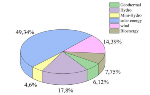
49% of Indonesia's potential renewable energy consists of solar energy, followed by 17% hydro-energy, and the rest of wind energy, geothermal, and bio-energy. Indonesia has a hydro-energy potential of 75,000 GW. Hydro-energy is the second-largest type of renewable energy, as shown in Figure 1 (a). The installation of a hydro-energy source is 4,621 GW, as shown in Figure 1(b). This fact indicates that hydro energy development has an excellent opportunity to increase the renewable energy mix in the energy supply in Indonesia [1]. Efforts to increase hydro energy installations include developing turbine designs to improve performance, then increasing the volume of buildings in Indonesia.
A hydro-turbine is a primary tool to convert hydro energy into electrical energy. Figure 2 shows the types of hydro-turbines, divided into five classes. Turbines are generally divided into Vertical, venturi, Gravitational Vortex, cross-flow, and axial. Vertical axis turbines consist of Savonius and Darrieus. Axial axis turbines have three types: inclined Axis, Rigid mooring, and submerger generator [2]. Research on hydro-turbines has developed recently, such as Savonius [3-6], Darrieus [7], and cross-flow. Savonius and cross-flow is a hydro-turbine with a circular runner. Savonius is one of the rotors that work using drag force. Some geometric variations are Shape of blade 4 [8, 9], Phase-shift angel [10] and stage's number [11]. Cross-flow consists of a runner and nozzle that works from the kinetic energy generated from flowing water. Factors that influence the performance of cross-flow turbines are the blade's number [12], shaft diameter [13], thickness, nozzle entry [14], and nozzle axis [15]. This research is to analyze the effect of geometry on water turbine performance. Perform variations on the number of blades 12-blades, 24-blades, 36-blades, and 48-blades.
(a)
(b)
Figure 1. (a) Capacity of renewable energy; (b) Installed of renewable energy power plants
Figure 2. Classification of Hydrokinetic Turbines [2]
The computational Fluid dynamics method was used in this research. The research was carried out on a three-dimension case study. This study aimed to determine the effect of rotational speed and blade number on the aerodynamic performance of a cross-flow turbine, like the coefficient of power. The influence of the blade’s number and rotational speed was analyzed using a factorial design analysis (2-factor). This analysis can obtain a significant value and determine the effect of interactions between factors [16-20].
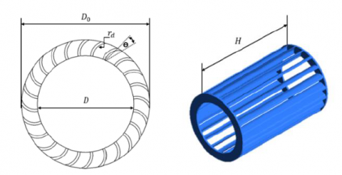
This research has been carried out using a blade angle of 30˚ on the runner in a hydro turbine with a cross-flow type. Figure 3 shows the runner design of the cross-flow turbine. The dimensions used for the cross-flow runner are shown in Table 1, with the geometry description in Figure 3. This research was carried out on a turbine with a number of blades 12, 24, 36, and 48. The turbine performance is shown by several parameters, including the aerodynamic performance, like the coefficient of torque (Ct) and coefficient of power (Cp). So that the simulation results are converted to these parameters as shown in Eqns. (1-5), these equations are as follows [20]:
$P_A=0,5 \times \rho \times A \times V^3$ (1)
$T S R=\frac{\omega D}{2 V}$ (2)
$P_R=T \times \omega$ (3)
$C p=\frac{P_R}{P_A}$ (4)
$C t=\frac{C p}{T S R}$ (5)
Eq. (1) is used to find the power available, and Eq. (3) is used to find the power produced by the rotor. The ratio of inlet fluid velocity to rotational speed is shown by Eq. (2). Turbine performance is measured by the coefficient of power parameter in Eq. (4) and the coefficient of torque in Eq. (3).
Figure 3. Runner design
Table 1. Dimension of cross-flow runner
|
Symbol |
Description |
Value (mm) |
|
(D0) |
Outer Diameter |
80 |
|
(H) |
Height of Runner |
130 |
|
(rd) |
Blade Radius |
10 |
|
(D) |
Inner Diameter |
60 |
|
- |
Thickness |
1.5 |
|
(ϴ) |
The angle of Blade |
30° |
The research was carried out in three dimensions on cross-flow type hydro turbine using the computational fluid dynamics method. The CFD steps that have been used in this modeling are design, meshing, boundary conditions, and processing, which are carried out on the workbench in the Ansys software. The software used is Ansys with CFX. CFD Simulation on Ansys software is a solution using the finite volume method with the Reynold Averaged Navier-Stokes (R.A.N.S.) equation [20]. The governing equation is represented as continuity equation in Eq. (6) and momentum on Eqns. (7-9). The governing equation is as follows:
Continuity Equation:
$\frac{\partial(\rho u)}{\partial x}+\frac{\partial(\rho v)}{\partial y}+\frac{\partial(\rho w)}{\partial z}=0$ (6)
X-Momentum:
$\begin{aligned} \frac{\partial\left(\rho u^2\right)}{\partial x}+\frac{\partial(\rho u v)}{\partial y} & +\frac{\partial(\rho u w)}{\partial z} =-\frac{\partial \rho}{\partial x}+\frac{1}{R e}\left(\frac{\partial \tau_{x x}}{\partial x}+\frac{\partial \tau_{x y}}{\partial y}+\frac{\partial \tau_{x z}}{\partial z}\right)\end{aligned}$ (7)
Y-Momentum:
$\begin{aligned} \frac{\partial(\rho u v)}{\partial x}+\frac{\partial\left(\rho v^2\right)}{\partial y} & +\frac{\partial(\rho v w)}{\partial z} =-\frac{\partial \rho}{\partial y}+\frac{1}{R e}\left(\frac{\partial \tau_{x y}}{\partial x}+\frac{\partial \tau_{y y}}{\partial y}+\frac{\partial \tau_{y z}}{\partial z}\right)\end{aligned}$ (8)
Z-Momentum:
$\begin{aligned} \frac{\partial(\rho u w)}{\partial x}+\frac{\partial(\rho v w)}{\partial y} & +\frac{\partial\left(\rho v^2\right)}{\partial z} =-\frac{\partial \rho}{\partial y}+\frac{1}{R e}\left(\frac{\partial \tau_{x z}}{\partial x}+\frac{\partial \tau_{y z}}{\partial y}+\frac{\partial \tau_{z z}}{\partial z}\right)\end{aligned}$ (9)
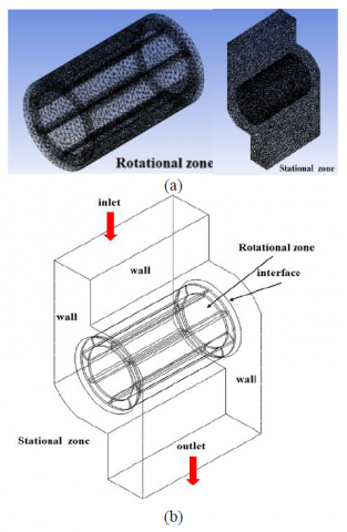
The simulation domain is divided into rotational and stationary zones [11, 20, 21]. The rotational and stationary zones have meshed with the same settings using the tetrahedron method [15]. The rotational zone and the stationary zone are linked by an interface, which is fluid to fluid. In some parts, inflation is carried out on the stationary zone walls and the runner walls on the rotational zone [12, 21]. The purpose of the inflation on the wall (in the stationary zone) and runner (in the rotating zone) is to provide a precise impact on the meshing, which exists between liquid and solid. The results of the meshing that has been done are shown in Figure 4(a). The Figure shows that the layer belongs to the inflation setting in the solid area in contact with the liquid.
Figure 4(b) shows the schematic of the simulation on ANSYS. The boundary conditions of the simulation consist of the inlet, outlet, wall, and interface. This research was conducted in steady conditions and using the turbulence type in this simulation is Shear Stress transport [22, 23]. The SST turbulence model's characteristics are accurate at low-Re values. As a result, this turbulence model is appropriate for this modeling. The target residual of this simulation is 10-3. Flow at the inlet and outlet is a subsonic flow [15]. The water velocity at the inlet is 3m/s, and the boundary condition at the outlet is a pressure of 1atm. The wall uses a wall-type condition with a no-slip condition, and the outlet uses an opening condition.
Figure 4. (a) Mesh configuration; (b) Schematic of simulation
A meshing independence study has been carried out by performing four variations of mesh settings. Variations in mesh settings are based on the number of elements [12, 20, 24, 25]. The validation process is also carried out at this stage. Validation is done by comparing Makarim’s research with the simulation result. The value compared is the result of calculating the coefficient of the moment. The results of the mesh independence study are shown in Figure 5(a). For the mesh independence study and benchmarking results, setting no. 4 has been chosen, namely a mesh with the number of elements 990,991. Figure 5(b) shows the benchmarking results with the research of Makarim et al. [26].
(a)
(b)
Figure 5. (a) Relationship coefficient of the moment and the number of elements; (b) Benchmarking modeling with experiment
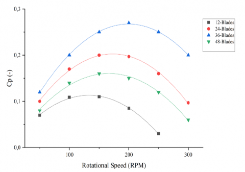
The coefficient of power generated from all the runner variations is shown in Figure 6. Cp increased at rotational speeds less than 150 rpm and decreased at rotational speeds greater than 150 rpm, as determined by research on 12-blade runners. The 12-blade runner has achieved the Cpmax of 11%. A runner with 24-blade was similar to a 12-blade runner. Cp decreases at more than 150 rpm and increases at a rotational speed of less than 150 rpm. The resulting Cpmax is 20%. For the runner with 36-blades, Cp increased at a rotation speed of less than 200 rpm and then decreased at a rotation speed of more than 200 rpm. The Cpmax produced by the 36-blade runner is 27%. The 48-blade runner delivers a Cpmax of 16%.
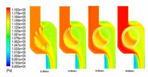
In addition to generating Cp values, this simulation produces output in the form of contours. The contour shown is the pressure contour shown in Figure 7. The pressure contour shows the higher the pressure at the inlet for all runner variations. It can be seen from the resulting color getting closer to red. But in general, the resulting contours are similar, where the pressure on the inlet side is greater than the pressure on the outlet side.
Figure 6. Performance curves Cp vs. Rotational Speed
Figure 7. Contours of pressure for Runner
Figure 8. Contours of velocity for cross-flow turbine
In addition to producing the Cp value [27-29], this simulation has output from contours and velocity vectors. Contours and velocity vectors for each type of rotor are shown in Figure 8. The velocity contour shows that the more the number of blades, the smaller the wake-zone area. The velocity vectors formed are similar for all variations. A runner with 36-blades has the densest speed density around the rotary domain. The greater the number of blades, the longer the rotation speed interval because the rotor can capture the speed of the water from the inlet flow so that the torque generated by the rotor is even greater.
Analysis of factorial designs using a two-factor model aims to determine the significance of factors and the interaction between both factors [10]. The factors used in the factorial design analysis are the number of blades and rotational speed. Table 2 shows the results of the analysis factorial design using a two-factor. F0 from Table 2 is compared with F in Table 3 to determine the influence between the rotational speed factor and the number of blade factors and obtained that F0 Rotational Speed in Table 2 is higher than F from Table 3, F0 Number of blades in Table 2 is lower than F from Table 3. These results show that the number of blades and Rotational Speed significantly affect the performance of a cross-flow turbine. F0 interaction lower than F from Table 3 shows that the rotational speed with the blade’s number does not influence each other.
Table 2. Analysis of variance for a rotational speed and number of blade factors on cross-flow turbine performance
|
Source of Variation |
Sum of Squares |
Degrees of Freedom |
Mean Square |
F0 |
|
Rotational Speed (A) |
0.020 |
4 |
0.005 |
8.10 |
|
Number of Blade (B) |
0.050 |
3 |
0.017 |
27.28 |
|
AB Interaction |
0.003 |
1 |
0.003 |
4.80 |
|
Error |
0.007 |
11 |
0.001 |
|
|
Total |
0.080 |
19 |
|
|
Table 3. Value of the F distribution [18]
|
|
Degrees of Freedom |
Value |
|
F0.05 (4,11) |
4 |
3.36 |
|
F0.05 (3,11) |
3 |
3.59 |
|
F0.05 (1,11) |
1 |
4.84 |
The simulation results that have been carried out show that the number of blades affects the performance of the cross-flow hydro-turbine. The best Cpmax results were obtained on a cross-flow hydro-turbine with 36 blades with a value of 27%, where the results are displayed for a blade angle of 30˚ and compared to 12-blade, 24-blade, and 48-blade conditions. Hydro-turbine type cross-flow with a rotor of 36 blades can be used as an alternative design. The results of the factorial design analysis show that the rotational speed and the number of blades have a high significant value. However, the rotational speed and the number of blades do not affect each other.
This work was supported by the RKAT PTNBH Universitas Sebelas Maret Year 2023, under the Community Service Scheme of “Program Kemitraan Masyarakat” (PKM-UNS), with the grant/contract no. 229/UN27.22/PT.01.03/2023. The authors gratefully acknowledge the support.
|
A |
Runner area |
|
CP |
Power coefficient |
|
CT |
Torque coefficient |
|
PA |
Power available |
|
PR |
Power rotor |
|
TSR |
Tip speed ratio |
|
T |
Torque |
|
V |
Free flow velocity |
|
u, v, w |
Velocity vector |
|
x, y, z |
Cartesian coordinates |
|
Greek Symbols |
|
|
ρ |
Density |
|
ω |
Angular velocity |
[1] Indonesia Energy Outlook 2021. (2021). Badan pengkajian dan penerapan teknologi, Jakarta, Indonesia.
[2] Ibrahim, W.I., Mohamed, M.R., Ismail, R.M.T.R., Leung, P.K., Xing, W.W., Shah, A.A. (2021). Hydrokinetic energy harnessing technologies: A review. Energy Reports, 7: 2021-2042, https://doi.org/10.1016/j.egyr.2021.04.003
[3] Prabowo, A.R., Prabowoputra, D.M. (2020). Investigation on Savonius turbine technology as harvesting instrument of non-fossil energy: Technical development and potential implementation. Theoretical and Applied Mechanics Letters 10(4): 262-269, https://doi.org/10.1016/j.taml.2020.01.034
[4] Herlambang, Y.D., Supriyo, S., Prasetiyo, B., Alfauzi, A.S. (2022). Experimental and simulation investigation on savonius turbine: Influence of inlet-outlet ratio using a modified blade shaped to improve performance. Evergreen, Joint Journal of Novel Carbon Resource Sciences & Green Asia Strategy, 9(2): 457-464, https://doi.org/10.5109/4794172
[5] Putrawan, O., Irwansyah, R., Nasution, S.B.S. (2022). The numerical study of the effect of blade depth and rotor-basin ratio on vortex hydro turbine performance. Evergreen, Joint Journal of Novel Carbon Resource Sciences & Green Asia Strategy, 9(2): 556-562. https://doi.org/10.5109/4794187
[6] Harsito, C., Tjahjana, D.D.D.P., Kristiawan, B. (2020). Savonius turbine performance with slotted blades. AIP Conference Proceedings, 2217: 030071. https://doi.org/10.1063/5.0000797
[7] Chong, W.T., Muzammil, W.K., Wong, K.H., Wang, C.T., Gwani, M., Chu, Y.J., Poh, S.C. (2017). Cross axis wind turbine: Pushing the limit of wind turbine technology with complementary design. Applied Energy, 207: 78-95. https://doi.org/10.1016/j.apenergy.2017.06.099
[8] Tjahjana, D.D.D.P., Arifin, Z., Suyitno, S., Juwana, W.E., Prabowo, A.R., Harsito, C. (2021). Experimental study of the effect of slotted blades on the Savonius wind turbine performance. Theoretical and Applied Mechanics Letters, 11(3): 100249. https://doi.org/10.1016/j.taml.2021.100249
[9] Ashwindran, S.N., Azizuddin, A.A., Oumer, A.N. (2021). Study of √2 conjecture in the construction of drag induced wind turbine blade morphology. Evergreen, Joint Journal of Novel Carbon Resource Sciences & Green Asia Strategy, 8(3): 574-585. https://doi.org/10.5109/4491649
[10] Prabowoputra, D.M., Prabowo, A.R. (2022). Effect of the Phase-Shift Angle on the vertical axis Savonius wind turbine performance as a renewable-energy harvesting instrument. Energy Reports, 8(Supplement 9): 57-66. https://doi.org/10.1016/j.egyr.2022.06.092
[11] Prabowoputra, D.M., Prabowo, A.R., Hadi, S., Sohn, J.M. (2021). Assessment of turbine stages and blade numbers on modified 3D Savonius hydrokinetic turbine performance using CFD analysis. Multidiscipline Modeling in Materials and Structures, 17(1): 253-272. https://doi.org/10.1108/MMMS-12-2019-0224
[12] Purwanto, P., Budiono, B., Hermawan, H., Prabowoputra, D.M. (2022). Simulation study on cross flow turbine performance with an angle of 20° to the variation of the number of blades. International Journal of Mechanical Engineering and Robotics Research, 11(1): 31-36. https://doi.org/10.18178/ijmerr.11.1.31-36
[13] Sirojuddin, S., Fajar, M.H., Sukarno, R. (2021). Investigation of reduction of Banki turbine shaft diameter to increase power. AIP Conference Proceedings, 2403: 70005. https://doi.org/10.1063/5.0071148
[14] Anand, R.S., Jawahar, C.P., Bellos, E., Malmquist, A. (2021). A comprehensive review on Crossflow turbine for hydropower applications. Ocean Engineering, 240: 110015. https://doi.org/10.1016/j.oceaneng.2021.110 015
[15] Kaunda, C.S., Kimambo, C.Z., Nielsen, T.K. (2014). A numerical investigation of flow profile and performance of a low cost Crossflow turbine. International Journal of Energy & Environment, 5(3): 275-296.
[16] Sartomo, A., Prabowoputra, D.M., Suyitno, S. (2020). Factorial design of the effect of reaction temperature and reaction time on biodiesel production. AIP Conference Proceedings, 2217: 30052. https://doi.org/10.1063/5.0000505
[17] Prabowoputra, D.M., Sartomo, A., Suyitno, S. (2020). The effect of pressure and temperature on biodiesel production using castor oil. AIP Conference Proceedings, 2217: 30051. https://doi.org/10.1063/5.0000504
[18] Montgomery, D.C. (2017). Design and Analysis of Experiments. John Wiley & Sons.
[19] Prabowoputra, D.M., Hadi, S., Prabowo, A.R., Sohn, J.M. (2020). Performance assessment of water turbine subjected to geometrical alteration of savonius rotor BT. Proceedings of the 6th International Conference and Exhibition on Sustainable Energy and Advanced Materials, Springer Nature, 351-365.
[20] Dragomirescu, A. (2011). Performance assessment of a small wind turbine with crossflow runner by numerical simulations. Renewable Energy, 36(3): 957-965. https://doi.org/10.1016/j.renene.2010.07. 028
[21] Prabowoputra, D.M., Hadi, S., Sohn, J.M., Prabowo, A.R. (2020). The effect of multi-stage modification on the performance of Savonius water turbines under the horizontal axis condition. Open Engineering, 10(1): 793-803. https://doi.org/10.1515/eng-2020-0085
[22] Xie, L., Du, Q., Liu, G. Lian, Z., Liu, J. (2021). Flow characteristics in turbine wheel space cavity. Energy Reports, 7: 2262-2275. https://doi.org/10.1016/j.egyr. 2021.04.014
[23] Tiwari, G., Kumar, J., Prasad, V., Patel, V.K. (2020). Utility of CFD in the design and performance analysis of hydraulic turbines — A review. Energy Reports, 6: 2410-2429. https://doi.org/10.1016/j.egyr.2020.09.004
[24] Mehr, G., Durali, M., Khakrand, M.H., Hoghooghi, H. (2021). A novel design and performance optimization methodology for hydraulic Cross-Flow turbines using successive numerical simulations. Renewable Energy, 169: 1402-1421. https://doi.org/10.1016/j.renene. 2021.01.090
[25] Takeyeldein, M.M., Lazim, T.M., Ishak, I.S., Mohd, N.A.R.N. (2020). Wind lens performance investigation at low wind speed. Evergreen, Joint Journal of Novel Carbon Resource Sciences & Green Asia Strategy, 7(4): 481-488. https://doi.org/10.5109/4150467
[26] Makarim, D.A., Tjahjana, D.D.D.P., Cahyono, S.I., Mazlan, S.A. (2019). Performance investigation of the crossflow water turbine by using CFD. AIP Conference Proceedings, 2097: 30083. https://doi.org/10.1063/1.5098258
[27] Prabowoputra, D.M., Hadi, S., Prabowo, A.R., Sohn, J.M. (2020). Performance investigation of the savonius horizontal water turbine accounting for stage rotor design. International Journal of Mechanical Engineering and Robotics Research, 9(2): 184-189. https://doi.org/10.18178/ijmerr.9.2.184-189
[28] Alim, M.I.A., Hadi, S., Tjahjana, D.D.D.P. (2022). Effect of turbine blades transformation on savonius turbine performance. Mekanika, 21(1): 26-30. https://dx.doi.org/10.20961/mekanika.v21i1.48619
[29] Prabowoputra, D.M., Prabwo, A.R., Yaningsih, I., Tjahjana, D.D.D.P., Laksono, F.B., Adiputra, R., Suryanto, H. (2023). Effect of blade angle and number on the performance of Bánki Hydro-Turbines: Assessment using CFD and FDA approaches. Evergreen, Joint Journal of Novel Carbon Resource Sciences & Green Asia Strategy, 10(1): 519-530.