Hayder H. Khaleel![]()
© 2023 IIETA. This article is published by IIETA and is licensed under the CC BY 4.0 license (http://creativecommons.org/licenses/by/4.0/).
OPEN ACCESS
Gas turbine has been used in many modern applications such as electric power plants and airplane engines. Turbine propellers are usually under high load and high temperature therefore; it is necessary to study their behavior under loads before catastrophic failure. This work aims to investigate numerically the behavior of gas turbine propeller fabricated of three materials that were stainless steel, E-glass fiber and carbon fiber under various loads (2000, 4000, 6000) N to get the total deformation, maximum strain. Maximum stress and shear stress. The simulation was achieved using solidwork 2016 and the analysis was done using ANSYS 2020. The results showed that stainless steel showed less deformation than the other two materials.
turbine propeller, E-glass, carbon fiber, total deformation, stress
Using turbine technology, the most energy can be obtained from the processing fluid in a way that works in conjunction with the maximum effectiveness throughout an efficient plant, with little costs, a limited testing time, and a short start [1]. The gas turbine blades are subject to significant mechanical loads, high-temperature loads, aerodynamic loads, etc., because of the high radius of the structure and the massive mass of the blade, and it is challenging to design the structural strength and life [2]. Usually, gas turbine blades are manufactured from super alloys such as nickel-base and cobalt-base super alloys because of their outstanding strength under high loads and high temperatures [3]. composite materials such as e-glass fiber and carbon fiber have been used recently in the fabrication of turbine blades because of their superior characteristics such as high strength–weight ratio and fatigue resistance [4]. For the computer simulation of blades' behavior, a number of modern FEM models are utilized such as ANSYS and ABAQUS are widely used packages. The design of the blades has high precision and simulation of their dynamic behavior, considering nonlinear geometric and physical effects when required [5, 6]. Many researchers studied numerically the analysis of gas turbine propeller under different mechanical loads. Gowreesh et al. [7] analyzed the design of the first stage rotor blade of a two-stage gas turbine. utilizing the finite element analysis software ANSYS The evaluation of rotor blade temperature field. utilizing this software model, work was completed and applied boundary conditions. The static loads and temperature were influential on the blades of the gas turbine. Yang et al. [8] studied a three-dimensional model using finite elements. The analysis of the blade strength of turbine blades in complex conditions under the joint responsibility of temperature load, centrifugal load, and aerodynamic load. Boyaraju et al. [9] designed a solid model, CATIA V5 was used. The structure and Thermal analysis were performed on the various models comprised of the two materials AL 2024 and T6. By comparing the models, the model with T6 has the lowest temperature, and the model with T6 also has the lowest fluxes. Tarfaoui et al. [10] modeled the response of blades and gain a thorough understanding of the mechanical behavior of the constructions, the most cutting-edge features of finite element (FE) abaqus/Implicit have been used. The susceptible parts have subsequently been located. Teja et al. [11] This research presented a summary of the numerical analysis of vertical axis gas turbine rotor blade components using various conventional and cutting-edge materials. For the design of the model and optimization study for the structural, thermal, and modal of gas turbine rotor blade components, CATIA V5 and ANSYS 11.0 are utilized. Titanium, graphite, and zirconium were the rotor blade materials used in the optimization analysis. The effectiveness of the optimization was assessed by comparing the results of an investigation of the turbine rotor blade components made of graphite, titanium, and zirconium alloys. The results showed that, in comparison to graphite and zirconium, titanium alloy is a stronger replacement for usage as a rotor blade element in gas turbines. This work aims to investigate numerically the behavior of gas turbine propeller fabricated of three materials that were stainless steel, E-glass fiber and carbon fiber under various loads (2000, 4000, 6000) N to get the directional deformation which is the deformation in a direction which the force is applied normally on the turbine blade, total deformation which is the square root of the total of the square of X, Y & Z direction, maximum strain, Maximum stress which is the σ1 that calculated a stress transformation at a point for the blades under loads and maximum shear stress which is the greatest shear that can be found in small area. The simulation was achieved using solidwork 2016 and the analysis was done using ANSYS 2020.
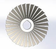
The turbine propeller was simulated and analyzed using the finite element method with different materials which were stainless steel, e-glass fiber and carbon fiber in order to study the behavior of these materials under different loads in order to obtain total deformation, strain, stress and shear stress. First of all, the turbine propeller was designed and simulated using solidwork 2016 with the outer diameter of the turbine is 410 mm and inner diameter is 130 mm and angle for each blade is 2° with 30 blades as shown in Figure 1.
Figure 1. Turbine propeller
The mechanical properties of materials used in this work were stainless steel, e-glass and carbon fiber in Table 1.
Table 1. The mechanical properties
|
Material |
Density Kg/m3 |
Young modulus (GPa) |
Poisson ratio |
|
Stainless Steel |
7750 |
193 |
0.31 |
|
E-Glass Fiber |
2600 |
73 |
0.22 |
|
Carbon Fiber |
1800 |
230 |
0.2 |
Figure 2. The mesh of the turbine propeller
Figure 3. Convergence test
Figure 4. Boundary conditions
Ansys 2020 was used as a finite elements analyzer to study the behavior of the turbine propeller. The turbine blade meshed as shown in Figure 2 and then subjected to different loads which were (2000, 4000, 6000) N. The results obtained involved the total deformation, directional deformation, maximum strain, maximum stress and maximum shear stress.
The number of mesh that was used in this study was 30000 elements according to the convergence test as shown in Figure 3.
Boundary conditions that were used in this work fixed support at the inner radius of the turbine propeller and different normal forces on the turbine blades as shown in Figure 4.
The results in this work involved the turbine blades which were manufactured from three various materials (stainless steel, e-glass, carbon fiber) under three different loads (2000, 4000, 6000) N in order to compare their manner and obtain the total deformation, directional deformation, maximum strain, maximum stress and maximum shear stress as listed in Table 2, 3, 4 respectively.
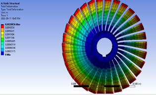
Figure 5 presents the total deformational for gas turbine blades under 4000 N for carbon fiber material.
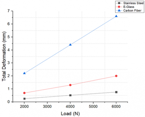
Figure 6 presents the comparison of the total deformation of the three materials under the three different loads. It could be noticed that the maximum total deformation occurred at load 6000 N for carbon fiber and it was 6.6 mm while the minimum total deformation happened in stainless steel under 2000N and it was 0.25 mm.
Figure 7 shows the total deformation for E-glass under 6000 N and Figure 8 shows the total deformation for stainless steel under force of 600 N.
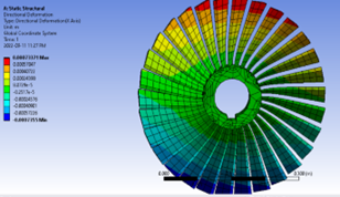
Figures 9, 10 and 11 show the directional deformation for the three materials under 6000 N.
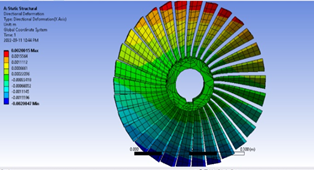
Figure 12 presents the comparison of directional deformation for the materials. The maximum directional deformation was 6.15 mm for carbon fiber and the minimum value was 0.24 mm for both stainless steel and E-glass fiber.
Figure 13 presents the stress contour for stainless steel under 6000 N.
Figures 14 and 15 show the stress distribution for E-glass and carbon fiber under 6000 N.
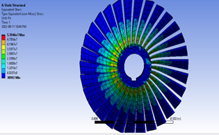
Figure 16 presents the maximum strain for the three materials under the various load. The maximum strain was in carbon fiber and it was 3.35 mm/mm under 6000 N while the minimum value was 0.0964 mm/mm for stainless steel under 2000 N.
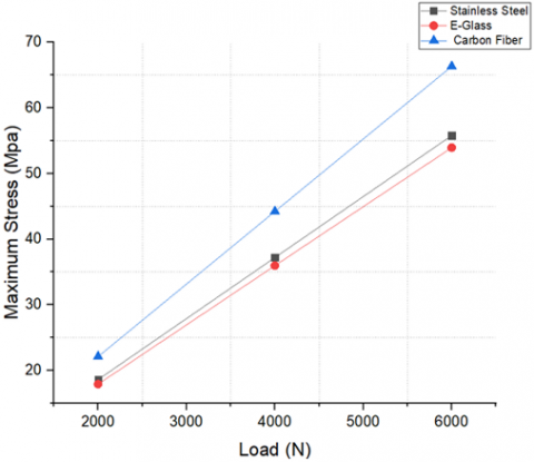
Figure 17 presents the maximum stress for the three materials. Maximum stress was 66.32 MPa for the carbon fiber under 6000 N while the minimum value was 17.9 MPa for the E-Glass fiber under 2000 N.
Figures 18, 19 and 20 show the maximum strain distribution for the three materials under load 4000 N.
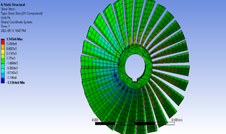
Figure 21 presents the maximum shear stress for the three materials. Maximum shear stress was 4.77 MPa for the stainless steel under 6000 N while the minimum value was 1.39 MPa for the E-Glass fiber under 2000 N. It could be noticed that carbon fiber behavior was nonlinear and this is because carbon fiber suffers from different failure modes under high loads such as delamination and cracking.
Figures 22, 23 and 24 show the shear stress distribution for the three various materials under the load of 2000 N.
Table 2. The results under 2000 N
|
Material |
Total deformation (mm) |
Directional deformation (mm) |
Max. strain (mm/mm) |
Max. stress (Mpa) |
Max. shear stress (Mpa) |
|
Stainless steel |
0.25 |
0.24 |
0.0964 |
18.6 |
1.59 |
|
E glass |
0.69 |
0.24 |
0.246 |
17.9 |
1.398 |
|
Carbon |
2.2 |
2 |
1.1 |
22.1 |
1.54 |
Table 3. The results under 4000 N
|
Material |
Total deformation (mm) |
Directional deformation (mm) |
Max. strain (mm/mm) |
Max. stress (Mpa) |
Max. shear stress (Mpa) |
|
Stainless steel |
0.512 |
0. 48 |
0.19 |
37.2 |
3.18 |
|
E glass |
1.3 |
1.33 |
0.49 |
35.96 |
2.8 |
|
Carbon |
4.4 |
4.1 |
2.2 |
44.21 |
3.9 |
Table 4. The results under 6000 N
|
Material |
Total deformation (mm) |
Directional deformation (mm) |
Max. strain (mm/mm) |
Max. stress (Mpa) |
Max. shear stress (Mpa) |
|
Stainless steel |
0.76 |
0.73 |
0.28 |
55.79 |
4.77 |
|
E glass |
2 |
2 |
0.74 |
53.94 |
4.19 |
|
Carbon |
6.6 |
6.15 |
3.35 |
66.32 |
4.63 |
Figure 5. Total deformation for carbon fiber
Figure 6. Total deformation for the three materials
Figure 7. Total deformation for E-glass under 6000 N
Figure 8. Total deformation for stainless steel under 6000 N
Figure 9. Directional deformation for stainless steel under 6000 N
Figure 10. Directional deformation for E-Glass under 6000 N
Figure 11. Directional deformation for carbon fiber under 6000 N
Figure 12. Directional deformation
Figure 13. Stress contour for stainless steel under 6000 N
Figure 14. Stress contour for E-glass under 6000 N
Figure 15. Stress contour for carbon fiber under 6000 N
Figure 16. Maximum strain
Figure 17. Maximum stress
Figure 18. Maximum strain for stainless steel under 4000 N
Figure 19. Maximum strain for Carbon fiber under 4000 N
Figure 20. Maximum strain for E-Glass under 4000 N
Figure 21. Maximum shear stress
Figure 22. Shear stress for stainless steel under 2000 N
Figure 23. Shear stress for E-glass under 2000 N
Figure 24. Shear stress for carbon fiber under 2000 N
This paper presented the numerical analysis of turbine propeller blades fabricated for three various materials that were subjected to three different loads. The main conclusions were that the total deformation and directional deformation increased by increasing the loads for the three materials while the maximum deformation occurred in carbon fiber. The maximum stress also happened in carbon fiber and it was also increased by increasing the loads. The stainless steel showed less deformation than the two other materials and this is because of high elements in its alloy and complex microstructure. For the future works, it is recommended to use different materials with different loads such as high strength steels.
[1] Liu, Z., Karimi, I.A. (2018). Simulation and optimization of a combined cycle gas turbine power plant for part-load operation. Chemical Engineering Research and Design, 131: 29-40.
[2] Qian, Z., Li, G. (2022). Structure design and optimization of a gas turbine blade. In Journal of Physics: Conference Series, 2252(1): 012025. https://doi.org/10.1088/1742-6596/2252/1/012025
[3] Sahu, M.K. (2017). Comparative exergoeconomic analysis of basic and reheat gas turbine with air film blade cooling. Energy, 132: 160-170. https://doi.org/10.1016/j.energy.2017.05.025
[4] Jureczko, M., Mrówka, M. (2022). Multiobjective optimization of composite wind turbine blade. Materials, 15(3): 4649. https://doi.org/10.3390/ma15134649
[5] Mevada, K. (2020). Finite element analysis of wind turbine blade. International Journal of Scientific Development and Research, 5(1). http://www.ijsdr.org/papers/IJSDR2001001.pdf.
[6] Laird, D., Montoya, F., Malcolm, D. (2005). Finite element modelling of wind turbine blades. In 43rd AIAA Aerospace Sciences Meeting and Exhibit, p. 195. https://doi.org/10.2514/6.2005-195
[7] Gowreesh, S., Sreenivasalu Reddy, N., Yogananda Murthy, N.V. (2009). Convective heat transfer analysis of a aero gas turbine blade using ansys. International Journal of Mechanics and Solids, 4(1): 55-62.
[8] Yang, Y.J., Yang, L., Wang, H.K., Zhu, S.P., Huang, H.Z. (2016). Finite element analysis for turbine blades with contact problems. International Journal of Turbo & Jet-Engines, 33(4): 367-371. https://doi.org/10.1515/tjj-2015-0043
[9] Boyaraju, G., Rajasekhar, S., Sridhar, A.V., Rao, J.H.N. (2015). Thermal analysis of a gas turbine rotor blade. International Journal of Science Engineering and Advance Technology, 3(12): 1181-1187.
[10] Tarfaoui, M., Nachtane, M., Boudounit, H. (2020). Finite element analysis of composite offshore wind turbine blades under operating conditions. Journal of Thermal Science and Engineering Applications, 12(1): 011001. https://doi.org/10.1115/1.4042123
[11] Teja, P.S., Babu, P.K., Rao, K.K., Babu, M.M., Sreenivasan, M. (2020). Numerical analysis of vertical axis gas turbine blade of different materials. Materials Today: Proceedings, 33: 1038-1043. https://doi.org/10.1016/j.matpr.2020.07.054