Hend I. Alkhammash![]() | Laraib Majid Satti
| Laraib Majid Satti![]() | Nafees Ahmad
| Nafees Ahmad![]() | Ahmed Althobaiti
| Ahmed Althobaiti![]() | Nasim Ullah*
| Nasim Ullah*![]() | Abdulrahman Jamal Babqi
| Abdulrahman Jamal Babqi![]() | Asier Ibeas
| Asier Ibeas![]()
© 2023 IIETA. This article is published by IIETA and is licensed under the CC BY 4.0 license (http://creativecommons.org/licenses/by/4.0/).
OPEN ACCESS
This article outlines how to optimize the parameters of proportional integral (PI) and proportional resonant (PR) controllers of a grid connected three-phase inverter system using Particle Swarm Optimization (PSO). The optimization of the control parameters is constrained to a low total harmonic distortion (THD) in the injected currents to the grid. In contrast to conventional PI and PR tuning methods, the PSO optimized controller inherits a wide-ranging operating condition, having better performance in steady-state and rapid dynamic response under abnormal grid conditions. This approach is used to provide the simulation results under both abnormal and normal grid conditions. Some important characteristics of this technique are that its complexity is not altered, no additional hardware is required, and no additional cost is added. From the presented results, it is observed that the proposed control optimization method ensured a low THD of 0.59% in the injected grid currents. Moreover, the control parameter optimization error converges to zero in finite time.
photovoltaic energy, grid tied inverter, proportional integral control, proportional resonant control, total harmonic distortion (THD), optimization
Solar energy is the highly abundantly available renewable energy resource and is widely utilized in photovoltaic (PV) systems for energy production [1, 2]. PV generation systems have been used over the globe in recent times. Three different configurations of the PV systems are in use such as stand-alone PV systems, grid connected PV systems and hybrid systems [3, 4]. These system configurations are used based on the energy supply configuration and location of specific area [5]. In remote areas, grid connected PV systems along with battery storage backup are employed. Hybrid power systems are used in combination of wind, tidal and thermal energy with PV systems [6]. Despite all the extended usage and advantages of the PV systems, it is affected with the meteorological conditions. The variations in the sun irradiation and ambient temperature affects the performance and effectiveness of the PV system [7]. In conjunction with this, conventional grid regulations must be adhered while incorporation of the PV systems into the electrical power grid and most important parameter to consider is the power quality [8]. The Inverter systems used for grid integration are getting lighter and smarter with lower costs [9, 10]. The PV grid-tied inverter directly injects the power into the transmission system, which is considered as its fundamental benefit [11]. A detailed study has been conducted on single and three phase grid-tied inverters and several important aspects such as power quality issues, variation in solar irradiance and its effects on power injection, current wave forms quality under power dynamics and grid faults are elaborated and generic models are developed for future utilization [12]. Apart from the power quality issues, another important problem in the renewable energy integration to the grid is the grid inertia [13]. Bulk PV power penetration into grid makes no contribution in the grid inertia enhancement; rather the grid inertia is compromised. The reason is very obvious because the PV source is non-rotating; this it cannot contribute inertia like rotating machines. Forgoing in view, a grid with low inertia will be more prone to instabilities in the events when the injected current waveforms are associated with high THD, grid faults and disturbances.
PI controllers are widely utilized for many industrial systems due to its simplicity and ease in implementation. However, in certain applications, PI controllers cannot ensure stability of the system when the systems are subject to disturbances and parameters uncertainties. Specifically for PV applications, a PI control is proposed for a PV grid connected Z source inverter [14] with disturbance compensation capabilities. A double loop PI controller is presented for a bidirectional converter integrated PV/battery standalone DC power unit [15]. Similarly, a PI controller is effectively utilized in a quasi Z source boost inverter integrated off grid PV power system [16]. Apart from the utilization of PI controllers in the feedback loops, it is also widely utilized as maximum power point tracking controllers. A maximum power point tracking (mppt) algorithm, is formulated for a DC converter integrated standalone PV system using a classical PID control [17]. A PSO optimized PID mppt controller is discussed by Chamundeeswari and Seyezhai [18], while an adaptive PID mppt algorithm is proposed by Banakhr and Mosaad [19] for off grid PV system.
The fixed gain PID controllers discussed above are not robust against system disturbances, parameters variations and faults [20]. These shortcomings of PID control can be solved with adaptive control strategies that also include the optimization of the control parameters. The optimization of fuzzy-PI controller is achieved by genetic algorithms (GA) [21]. In another study, a fuzzy controller is designed by hierarchical genetic algorithm [22]. Direct power control (DPC) is a power regulation control strategy which performs better in presence of high frequencies, however, the benefit of DPC is its simplicity. Another challenge in DPC is the changeability of the frequency switching which makes the filter design more challenging [23]. These issues are resolved somehow with the use of proportional resonant (PR) control system [24], however; fixed gain PR controllers can also lead to poor performance under large system disturbances.
As discussed above, for the grid tied inverters, one major research challenge is to control it in way so that the THD in the injected grid current is minimum and within the range of the IEEE grid codes. PID controllers also find applications in THD minimization in the grid injected current. A PID control based THD minimization scheme is discussed by Shabbir et al. [25] for a sensored three phase rectifier. Similarly, a detailed analysis on the reduction of THD in an AC-DC converter in presented in the study of Suganya et al. [26].
Based on the above literature review, this research work presents Particle Swarm Optimization (PSO) for parameter tuning of PI and PR controller such that the grid tied inverter ensures minimum THD in the injected currents.
The major contributions of the research work are summarized below:
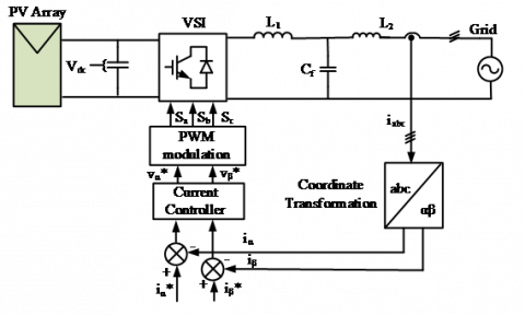
Figure 1 shows the single line diagram of a PV integrated grid tied inverter system. As shown in Figure 1, the DC power from PV source is integrated to the grid using a LCL coupled filter and an inverter unit. Current control loops are utilized to control the active and reactive power components of the electrical energy integration into the grid. One major challenge in the design of LCL filter and control loop is to ensure the smooth power integration with low THD values within the IEEE grid code standards. From the literature review part it is clear that PID controllers are widely utilized in industrial applications due to its simple structure and ease of implementation over hardware platforms. PR controllers are much similar to PI control; however, a major change in the topology is the inclusion of an additional filter with the integral term.
As discussed in the introduction section, the bulk power penetration from the non-rotating sources into grid makes no contribution in the grid inertia enhancement; rather the grid inertia is compromised. Thus in the grid tied inverters controller design steps, a fundamental research problem is to select optimal control parameters such that the THD in the injected grid currents is minimum. So the importance of optimization techniques play vital role in tuning the controller parameters as per the objective functions. In the next section, particle swarm optimization (PSO) technique is discussed with details.
Figure 1. Three-phase grid-connected inverter
The Particle Swarm Optimization (PSO) mathematical technique creates a unique implementation of an iterative optimization process inspired by the behaviour of swarming birds or bees moving at arbitrarily with in the space [18]. This technique provides optimal solutions for industry applications, electronic and digital communication, and different control systems. Several authors have proposed numerous changes in the PSO scheme. A new scheme by including inertia weight parameter was presented by Shi and Elbert which helped to achieve higher performance. The other frequent form of PSO is the inertia weight, which gradually decreases with iteration [21]. Each particle in the society of particles that constitutes the given technique represents a prospective remedy to an issue and modifies its "flying experience" within a predetermined boundary region. At first, every particle is distributed randomly. The theory of particle position and velocity has been used to express this method. An index vector for each particle's position effectively represents it i.e. $X_i^n=$ $\left[x_{i 1}, x_{i 2}, x_{i 3} \ldots x_{i n}\right]$ and a vector for its velocity $V_i^n=$ $\left[v_{i 1}, v_{i 2}, \ldots v_{i n}\right]$, here I represents the particle sequence number and n represents the iteration number [21]. The following mentioned equations are applied to update the initial position and velocity of the particle:
$\begin{aligned} V_{i d}^{n+1}=\omega \cdot V_{i d}^n+ & c_1 \cdot \text { rand } .\left(X_{\text {pbest }}^n-X_{i d}^n\right)+c_2 \cdot \operatorname{rand} .\left(X_{\text {gbest }}^n-X_{i d}^n\right)\end{aligned}$ (1)
$X_i^{n+1}=X_{i d}^n+V_{i d}^{n+1}$ (2)
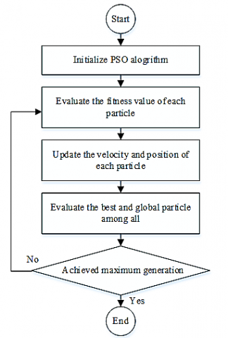
The best recorded global position vector, or $X_{g b e s t}^n$, in this scenario is referred to as the best particle among all particles. The best previously recorded position vector for each cycle is designated as $X_{\text {pbest }}^n$. Additionally, c1 and c2 are the constants of acceleration, rand generates a random number ranging from 0 up to 1, and ω represents inertial weight that balances the capabilities of "global" and "local" search [18]. Figure 2 depicts a flowchart of the PSO algorithm's optimization procedure. The particle positions and velocities are initialised. After each iteration the velocity and position of particles are altered. The mobility throughout the search space is determined by a performance function that assesses the fitness criteria of the particles. Depending on its own local best Pbest and the overall best of the entire swarm population Gbest, each particle's position can be modified. Each particle can have a different position depending on its own local best Pbest and the overall best of the entire swarm population Gbest. The procedure keeps going till the specified number of iterations has been reached. When predetermined stopping criteria are met or after multiple iterations have passed without a notable improvement, the process is likewise finished.
Figure 2. Flowchart for Particle Swarm Optimization (PSO)
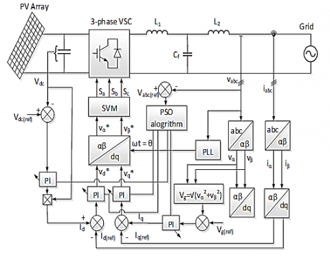
Figure 3. PSO-PI optimization
As shown in Figure 1, the dynamic response of the grid tied inverter, controller robust behavior, states steady state error and tracking accuracy are all significantly impacted by the selection of the current control loop. To control DC and grid voltages, PI controllers are utilized, please refer to Figure 3. From the control diagram presented in Figure 3, PI control loops are employed for regulation of grid voltage, PV DC voltage and current loops.
As a result, d-q current control uses the voltage controller outputs as its reference of current. This reference is applied to the three-phase grid current before it is supplied to the proper controller. A PSO optimization algorithm is applied for tuning the proportional and integral gains of the PI controllers.
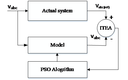
In a stationary reference frame, PSO can also be employed with a PR controller, as shown in Figure 4. Both times, the PSO algorithm is utilised to self-tune the control settings, and an integral time absolute error (ITAE) criteria is used as objective function. Since the structure of PI controller is easy to understand, so in the next section, PR controller is explained mathematically.
4.1 Proportional resonant controller
In this subsection, a proportional resonant (PR) controller is discussed. The voltages and currents in αβ frame are represented as follows:
$\left[\begin{array}{l}v_\alpha \\ v_\beta\end{array}\right]=\frac{2}{3}\left[\begin{array}{lll}1 & -\frac{1}{2} & -\frac{1}{2} \\ 0 & \frac{\sqrt{3}}{2} & -\frac{\sqrt{3}}{2}\end{array}\right]\left[\begin{array}{l}v_a \\ v_b \\ v_c\end{array}\right]$ (3)
$\left[\begin{array}{l}i_\alpha \\ i_\beta\end{array}\right]=\frac{2}{3}\left[\begin{array}{lrc}1 & -\frac{1}{2} & -\frac{1}{2} \\ 0 & \frac{\sqrt{3}}{2} & -\frac{\sqrt{3}}{2}\end{array}\right]\left[\begin{array}{l}i_a \\ i_b \\ i_c\end{array}\right]$ (4)
where, va, vb, vc represent the voltages in 3 phase system while ia, ib, ic represent corresponding currents. Also vα, vβ represent voltages and iα, iβ show the currents in the stationary frame. The voltage magnitude at the point of common coupling (PCC) is expressed as follows:
$\left|V_g\right|=\sqrt{V_{g \alpha}^2+V_{g \beta}^2}$ (5)
where, vgα and vgβ show grid side voltages. PR controller is represented in the following form:
$\mathrm{G}_{\mathrm{PR}}(\mathrm{s})=\mathrm{K}_{\mathrm{p}}+\mathrm{K}_{\mathrm{i}} \frac{\mathrm{s}}{\left(\mathrm{s}^2+\omega_{\mathrm{o}}^2\right)}$ (6)
The constant Kp represents the proportional term and Ki represents the integral term. Eq. (6) represents an ideal PR controller where the realization of the ideal controller is a challenging task. Thus the non- ideal PR controller introduced in Eq. (7).
$G_{P R}(s)=K_p+K_i \frac{2 \omega_{\mathrm{c}} s}{\left(s^2+2 \omega_{\mathrm{c}} s+\omega_0^2\right)}$ (7)
The calculation of the cost function gives the optimum solution. Integral-based cost functions, such as the ITAE, ISE and ITSE are commonly utilized [18]. In this research the ITAE approach is implemented as follows.
$T E A=\int t|e(t)| d t$ (8)
where, e(t) is the difference between the actual value and the reference value. Eq. (1) and Eq. (2) are used to minimize the cost function during the optimization process. Figure 5 illustrates the block diagram of the optimization process.
Figure 4. Optimization of PR controller
Figure 5. Basic algorithm structure of the PSO optimization
Eventually, for the PI and PR controller parameters Kp and Ki, each particle has a potential solution.
The simulation results of the three-phase grid-connected system using PSO optimized controllers are presented in this section.
5.1 Results using PSO optimized controllers
In this subsection, the results of stochastic optimization control approach with Particle Swarm Optimization are used to adopt better values for the gain for the controller. The proposed technique is built on an iterative optimization method that was prompted by animal swarm behavior.
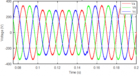
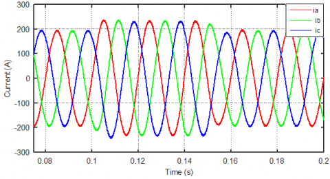
The control parameters are modified after each iterative step of the optimization process. Figure 6 demonstrates the three-phase grid voltage while Figure 7 illustrates the current waveforms employing PSO in the synchronous frame of reference which is based on PI control. The system is precisely designed over the entire 75% voltage sag event over a period of 0.1 to 0.15 seconds to evaluate the effectiveness of the system under the grid abnormal conditions. The output grid voltage and current waveforms produced by PSO-based control shows excellent results with minimum harmonic and ripple content.
Figure 6. Three-phase voltage waveform using PSO optimized PI control
The waveforms of the id and iq current components when the PI controller is utilized in the synchronous reference frame with PSO are shown in Figure 8 and Figure 9. During the abnormal grid conditions, an increment in the value of current can be seen. This is due to the fact that the PV array must transmit the same amount of active power to the grid both before and during voltage sag.
Figure 8 shows the waveforms of the id current while, Figure 9 shows iq current. The THD score of the currents will be discussed in the next section.
Figure 7. PSO-based three-phase current waveform using PSO optimized PI control
As a result, when the voltage falls, the current must rise to sustain the flow of active power. Summarizing this phenomenon, the voltage sag event shows that the computed current closely tracks the reference current.
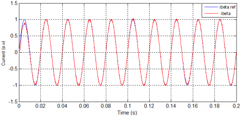
Figure 10 and Figure 11 depict the current iα and iβ waveforms, respectively by utilizing PSO optimized PR controller under normal ideal conditions. From the presented results, it is evident that the both current components track their reference commands precisely.
Figure 8. Measured and reference id current waveform using PSO optimized PI control
Figure 9. Measured and reference iq current waveform using PSO optimized PI contro
Figure 10. Measured and reference i-alpha using PSO optimized PR control
Figure 11. Measured and reference i-beta using PSO optimized PI control
5.2 Results using PSO optimized PR controllers and under abnormal grid conditions
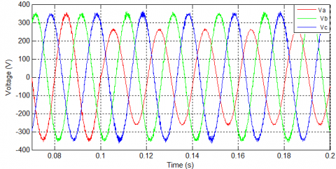
As illustrated in Figure 12, a line to ground fault voltage sag is introduced at the coupling common point (PCC) of the system.
Figure 12. Unbalanced voltage waveform
The performance of the inverter system with PSO tuned PR controller under application of unbalanced three phase voltages are verified in this section.
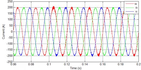
Figure 13 shows the three phase grids under the unbalanced voltage sags and PSO tuned PR controller. It is observed from the results, that the three phase currents are symmetrical under the application of the unbalanced three phase voltages.
Figure 13. Waveform of three-phase current using PSO optimized PR control
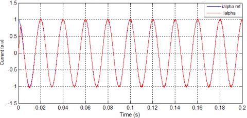
Figure 14. Measured and reference i_alpha under unbalanced condition using PSO optimized PR control
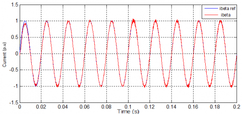
Figure 15. Measured and reference i_beta under unbalanced condition using PSO optimized PR control
Figure 14 and Figure 15 depict the iα and iβ current components respectively. As demonstrated in the figures, the measured currents components in the stationary frame of reference, successfully follows the reference current with PSO tuned PR controller. Moreover, it is observed that with PSO tuned PR Controller, the inverter system is robust to the application of unbalanced three phase voltages.
The updated information on the control parameters for each iteration is provided in Table 1. The procedure is concluded when predetermined stopping criteria are met or after a certain iteration, no apparent progress has been made.
Table 1. Iteration of the control parameters
|
Number of iteration |
Value of kp |
Value of Ki |
|
1 |
7.823 |
999.9845 |
|
2 |
7.767 |
999.976 |
|
3 |
6.4924 |
999.8743 |
|
4 |
6.4234 |
999.8741 |
|
5 |
6.221 |
999.7223 |
|
6 |
5.4975 |
999.5846 |
|
7 |
5.4924 |
999.1743 |
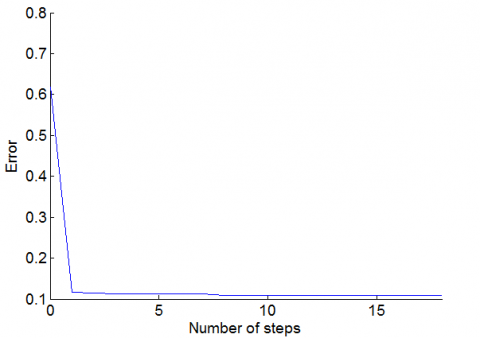
The absolute error signal of the integral is lowered to approximately zero after several cycles when the proposed technique is used with the PR as demonstrated in Figure 16.
Figure 16. Error convergence curve
5.3 THD comparison
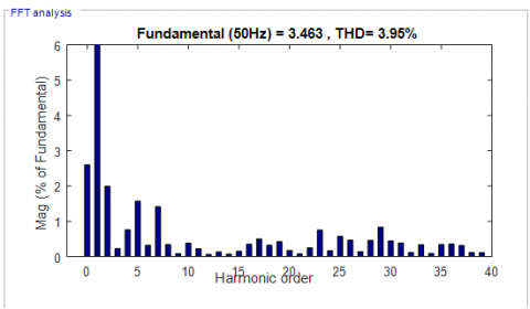
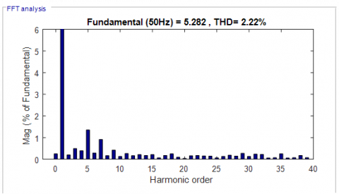
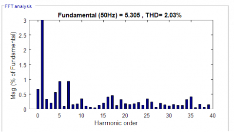
One of the research objectives of this work include the minimization of THD in the current waveforms using PSO optimized controllers. The results are presented in Figure 17 (a-d). Figure 17 (a-b) shows the % THD in the grid injected current waveforms using conventionally tuned PI and PR Controllers, while Figure 17 (c-d) shows the same with the PSO tuned PI and PR controllers respectively. With conventionally tuned PI controller, 3.95% THD is estimated in the grid injected current waveforms while with conventionally tuned PR controller 2.22%THD is recorded. PSO tuned PI and PR controllers showed better performance and the estimated THD scores are 2.03% and 1.93% for the PSO tuned PI and PR controllers respectively.
(a)
(b)
(c)
(d)
Figure 17. FFT of phase current waveforms: (a) Conventionally tuned PI controller; (b) Conventionally tuned PR controller; (c) PSO tuned PI controller; (d) PSO tuned PR controller
This research work successfully implemented PSO optimized PI and PR controllers for PV integrated grid tied inverter system. The research objective on how to minimize the % THD score in the injected grid currents is achieved. With PSO tuned PI and PR controller, lower % THD scores are estimated as compared to the conventionally tuned PI and PR controllers. Future application of the proposed method includes its hardware implementation using Field Programmable Gate Array (FPGA) technology for stand alone or grid tied PV power systems.
The work was supported by the Research Groups Program funded by Deanship of Scientific Research, Taif University, Ministry of Education, Saudi Arabia, [1-441-106].
[1] Afshari, E., Moradi, G.R., Rahimi, R., Farhangi, B., Yang, Y., Blaabjerg, F., Farhangi, S. (2017). Control strategy for three-phase grid-connected PV inverters enabling current limitation under unbalanced faults. IEEE Transactions on Industrial Electronics, 64(11): 8908-8918. https://doi.org/10.1109/TIE.2017.2733481
[2] Bawazir, R.O., Cetin, N.S. (2020). Comprehensive overview of optimizing PV-DG allocation in power system and solar energy resource potential assessments. Energy Reports, 6: 173-208. https://doi.org/10.1016/j.egyr.2019.12.010
[3] Benz, C.H., Franke, W.T., Fuchs, F.W. (2010). Low voltage ride through capability of a 5 kW grid-tied solar inverter. In Proceedings of 14th International Power Electronics and Motion Control Conference EPE-PEMC 2010, pp. T12-13. https://doi.org/10.1109/EPEPEMC.2010.5606829
[4] Ueda, Y., Kurokawa, K., Kitamura, K., Yokota, M., Akanuma, K., Sugihara, H. (2009). Performance analysis of various system configurations on grid-connected residential PV systems. Solar Energy Materials and Solar Cells, 93(6-7): 945-949. https://doi.org/10.1016/j.solmat.2008.11.021
[5] Borni, A., Abdelkrim, T., Bouarroudj, N., Bouchakour, A., Zaghba, L., Lakhdari, A., Zarour, L. (2017). Optimized MPPT controllers using GA for grid connected photovoltaic systems, comparative study. Energy Procedia, 119: 278-296. https://doi.org/10.1016/j.egypro.2017.07.084
[6] Buzo, R.F., Barradas, H.M., Leão, F.B. (2021). Fault current of PV inverters under grid-connected operation: A review. Journal of Control, Automation and Electrical Systems, 32(4): 1053-1062. https://doi.org/10.1007/s40313-021-00729-6
[7] Chine, W., Mellit, A., Pavan, A.M., Kalogirou, S.A. (2014). Fault detection method for grid-connected photovoltaic plants. Renewable Energy, 66: 99-110. https://doi.org/10.1016/j.renene.2013.11.073
[8] Ali Khan, M.Y., Liu, H., Yang, Z., Yuan, X. (2020). A comprehensive review on grid connected photovoltaic inverters, their modulation techniques, and control strategies. Energies, 13(16): 4185. https://doi.org/10.3390/en13164185
[9] Díez-Mediavilla, M., Dieste-Velasco, M.I., Rodríguez-Amigo, M.D.C., García-Calderón, T., Alonso-Tristán, C. (2014). Performance of grid-tied PV facilities based on real data in Spain: Central inverter versus string system. Energy Conversion and Management, 86: 1128-1133. https://doi.org/10.1016/j.enconman.2014.06.087
[10] Bacha, S., Picault, D., Burger, B., Etxeberria-Otadui, I., Martins, J. (2015). Photovoltaics in microgrids: An overview of grid integration and energy management aspects. IEEE Industrial Electronics Magazine, 9(1): 33-46. https://doi.org/10.1109/MIE.2014.2366499
[11] Guenounou, O., Belkaid, A., Colak, I., Dahhou, B., Chabour, F. (2021). Optimization of fuzzy logic controller based maximum power point tracking using hierarchical genetic algorithms. In 2021 9th International Conference on Smart Grid (icSmartGrid), pp. 207-211. https://doi.org/10.1109/icSmartGrid52357.2021.9551249
[12] Guerrero-Perez, J., De Jodar, E., Gómez-Lázaro, E., Molina-Garcia, A. (2014). Behavioral modeling of grid-connected photovoltaic inverters: Development and assessment. Renewable Energy, 68: 686-696. https://doi.org/10.1016/j.renene.2014.02.022
[13] Gui, Y., Wang, X., Blaabjerg, F. (2018). Vector current control derived from direct power control for grid-connected inverters. IEEE Transactions on Power Electronics, 34(9): 9224-9235. https://doi.org/10.1109/TPEL.2018.2883507
[14] Chuang, M., Hong, L. (2019). Research on photovoltaic grid-connected control of Z source inverter based on active disturbance rejection technology. In 2019 IEEE 4th Advanced Information Technology, Electronic and Automation Control Conference (IAEAC), 1: 2648-2652. https://doi.org/10.1109/IAEAC47372.2019.8997945
[15] Bhagiya, R.D., Patel, R.M. (2019). PWM based double loop PI control of a bidirectional DC-DC converter in a standalone PV/battery DC power system. In 2019 IEEE 16th India council international conference (INDICON), pp. 1-4. https://doi.org/10.1109/INDICON47234.2019.9028974
[16] Yadav, A., Chandra, S. (2020). Single stage high boost Quasi-Z-Source inverter for off-grid photovoltaic application. In 2020 International Conference on Power Electronics & IoT Applications in Renewable Energy and its Control (PARC), pp. 257-262. https://doi.org/10.1109/PARC49193.2020.236603
[17] Mohammed, F.A., Bahgat, M.E., Elmasry, S.S., Sharaf, S.M. (2022). Design of a maximum power point tracking-based PID controller for DC converter of stand-alone PV system. Journal of Electrical Systems and Information Technology, 9(1): 9. https://doi.org/10.1186/s43067-022-00050-5
[18] Chamundeeswari, V., Seyezhai, R. (2017). PSO-PID maximum power point tracking controller using modified superlift Luo converter. Energy Procedia, 117: 87-94. https://doi.org/10.1016/j.egypro.2017.05.110
[19] Banakhr, F.A., Mosaad, M.I. (2021). High performance adaptive maximum power point tracking technique for off-grid photovoltaic systems. Scientific Reports, 11(1): 20400. https://doi.org/10.1038/s41598-021-99949-8
[20] Hassan, Z., Amir, A., Selvaraj, J., Rahim, N.A. (2020). A review on current injection techniques for low-voltage ride-through and grid fault conditions in grid-connected photovoltaic system. Solar Energy, 207: 851-873. https://doi.org/10.1016/j.solener.2020.06.085
[21] Borni, A., Bouarroudj, N., Bouchakour, A., Zaghba, L. (2017). P&O-PI and fuzzy-PI MPPT controllers and their time domain optimization using PSO and GA for grid-connected photovoltaic system: A comparative study. International Journal of Power Electronics, 8(4): 300-322. https://doi.org/10.1504/IJPELEC.2017.085199
[22] Gui, Y., Wang, X., Blaabjerg, F., Pan, D. (2019). Control of grid-connected voltage-source converters: The relationship between direct-power control and vector-current control. IEEE Industrial Electronics Magazine, 13(2): 31-40. https://doi.org/10.1109/MIE.2019.2898012
[23] Kennedy, J., Eberhart, R. (1995). Particle swarm optimization. In Proceedings of ICNN'95-International Conference on Neural Networks, 4: 1942-1948. https://doi.org/10.1109/ICNN.1995.488968
[24] Althobaiti, A., Ullah, N., Belkhier, Y., Jamal Babqi, A., Alkhammash, H.I., Ibeas, A. (2022). Expert knowledge based proportional resonant controller for three phase inverter under abnormal grid conditions. International Journal of Green Energy, 1-17. https://doi.org/10.1080/15435075.2022.2107395
[25] Shabbir, M.N.S.K., Rahman, M., Afrin, F., Shila, S., Hossain, M.S. (2016). Improvement of PF and reduction of THD using PID controlled current sensored three phase rectifier. In 2016 3rd International Conference on Electrical Engineering and Information Communication Technology (ICEEICT), pp. 1-6. https://doi.org/10.1109/CEEICT.2016.7873073
[26] Suganya, R., Kamaraj, N., Sudalaimani, M. (2014). Reduction of THD in Single Phase AC to DC Boost Converter using PID controller. In 2014 IEEE International Conference on Advanced Communications, Control and Computing Technologies, pp. 147-151. https://doi.org/10.1109/ICACCCT.2014.7019358