Hayder Q. Majeed* | Basim Sh. Abed | Ali Khairi Ibrahim
© 2022 IIETA. This article is published by IIETA and is licensed under the CC BY 4.0 license (http://creativecommons.org/licenses/by/4.0/).
OPEN ACCESS
In current study a computation fluid dynamic (CFD) technique was used to investigate the effect of groynes shape and spacing on the scour pattern and the maximum scour depth in open channel flow. CFD model have been validated throughout comparing the numerical results with three previous experimental studies for a single groyne located in open channel with three different shapes (L, quadrant, and parabola shapes). The comparison revealed very good agreement between numerical results of the maximum scour depth with the results of all experimental models. Moreover, investigations of the effect of multi-groynes (three groynes and four groynes) arranged in parallel with constant spacing and also with variable spacing have been done, the results showed that the best spacing between groynes equal to the length of the groyne itself, Finally, the CFD model have been used to investigate the best pattern for the groynes having different shapes arranged respectively, the results show that the pattern starting with parabola shape gives minimum scouring depth.
groynes, scour depth, CFD, parabola shape, fluent software
Erosion in channels is common problem facing water resources engineers. Groynes are the most common structures used for treating bank erosion. They act as river training works utilized to regulate flow in rivers. They have been known as hydraulic structures aligned pointing upstream (repelling) and pointing downstream (deflecting) of the flow in river and protecting the bank against erosion, reducing the velocity of flow along river banks [1]. Scour around groyne can cause serious problems, such as weakening structure stability [2], so scour is a normal problem as a result of turbulence in channel when flow attack river banks and abutment of bridge. It is caused by the erosion process of flowing water, that separating material and moves it from the bed and banks of rivers as well as happening erosion proximity of abutment and groynes [3].
Kang et al. [4] used compound groyne (groyne and groyne arm) to study the impact of flow around compound groynes with different arm angles and lengths, they found that the ratio velocity increasing about 10% in downstream, and the size of recirculation area at upstream was increased with length of groyne as well as the recirculation area at URG is greater than DRG.
Möws and Koll [5] conducted laboratory experiments on straight flume by use a single inclined groyne only during the experiments. The purpose of their study was to study the characteristics of scour hole around groyne that include hole dimensions, depth of scour, contraction ratio, and other patterns. The experiments were carried out through three stages, the first stage, module was set perpendicular to the flume wall with different contraction ratio while in the second and third stages installed angle was change between 30° to 60° from the flume wall. They found that the main cause of scour was vortex which increased the power with the increase in contraction ratio, but its effect diminished at low Froude number values even for larger values of contraction ratio.
Dawood [6] focused on the estimation of scour depth around groyne by using three modules in this study (straight, T- shape, and L-shape). The scour depth was increased with the increase in flow velocity, Froude number, and water depth when the spacing between groynes was fixed. In addition to use different spacing (1, 1.5, and 2) times length of groyne, it has been observed when the groyne spacing increased by 0.5 led to increase in the amount of scour depth by 20% approximately.
The main purpose of the study is to compare these results with previous studies of same flow condition (Froude number, flow depth, number of groynes, and spacing between them) but she used two physical modules (quadrant and semi-parabolic shape) [7]. Additionally, three different groynes arrangements were used, and these arrangements were single, double, and triple. Experimental data showed that scour depth in semi-parabolic shape decrease by 75% compare with the quadrant shape. So, the quadrant shape is considered the best one compared to other models.
Dehghani et al. [8] study was to estimate the local scour depth and knowledge maximum scour depth by using two shapes (straight, L-head groynes in both direction). Their study was carried out by using two groups, the first group, comprised of two different shapes, the second group, comprised of upstream and downstream L- head groynes with various angles in both directions. It has been found that the optimum (ϴ) was 110° for L- Head groynes pointing downstream, and it was 60° for groynes pointing upstream.
This study aims to simulate and investigate the effect of groynes shape and spacing on the scour pattern and the maximum scour depth in open channel flow using Computation Fluid Dynamic (CFD) technique, as well as studying the effect of the spacing variation between the multi groynes and their shape on the maximum scour depth.
Since there are many experimental studies have been successfully applied to model local scour in a single and multiple groynes in a river. However, three-dimensional scour simulations around groynes have rarely been achieved. This limitation in use computational fluid dynamic (CFD) technique for this purpose may be most models are based on structured curvilinear boundary-fitted grids that have hard to correspond to the complex geometry of groynes such as parabola shape. Another reason for this limitation is computational time, which is still today significantly larger than the time required to compute a local scour depth and sediment removal around the hydraulic structures in a physical model. In spite of that, numerical models can provide valuable information in the future when computer performance expected to increase even more.
Fluent software is a commercial CFD package which is currently widely used for hydraulic engineering applications. The free surface of the flow in the open channel have been simulated by the Volume-of-Fluid (VOF) method. A user defined function should be impeded in the Fluent software using bed sediment equations from literature to simulate the real behaviour of the local scour close to the groynes that development under clear-water conditions.
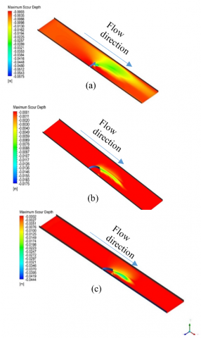
The simulations described here are run using FLUENT, a validation of the CFD model had been carried out with three different shapes singular groynes were studied experimentally in early studies (I, quadrant, and parabola shapes) the comparison is made with the maximum scour depth around the groyne with flow time as shown in Figures 1 and 2.
Figure 1. Maximum scour depth of singular groynes for different shapes
Figure 2. Maximum scour depth contour-lines of singular groynes of (a) I-shape, (b) quadrant -shape, (c) parabola-shape
There are many factors effect on the scour mechanism in the open channel flow such as flow properties i.e., flow discharge, flow depth, soil properties such as particle size, uniformity and consistency of the soil, and also hydraulic structures located in the rivers for example the shape of this structures and the ratio of blockage inside the river. In this section, just the effect of spacing between the groynes and their shapes will be discussed since these two factors have significant effects on the scour pit and there few studies on these factors.
4.1 Effect of spacing between groynes on the maximum scour depth
In this section the effect of spacing (S) between groynes have been investigated by ranging the space between them from L to 2L where L equal to the width of the groyne (in this study L=0.13m which is corresponded to experimental data) as shown in Figure 3. The method of investigation in this research have been done by coupling the k-ω SST model with dynamic mesh technique [9, 10]. The cross section for all open channel models in this study have been taken as 0.4 m width and 0.03 m height and 3 m length and for soil properties the particle size d50 is equal to 0.7 mm, and water flow average velocity has been equal to 0.25 m/s which corresponded to the previous experimental boundary conditions.
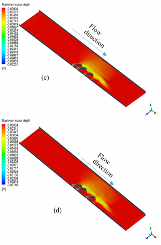
Figure 3. Maximum scour depth contour-lines of 3-groynes with (a) S=0.5L, (b) S=1L, (c) S=1.5L, (d) S=2L
It can be clearly noticed that the maximum scour depth around the groynes have less value when the spacing between groynes is constant compared with non-constant spacing. This may be because the mechanism of vortices generated close the groynes which depend on the groynes distribution. In addition to that, Figure 4 shows the maximum scour depth for parabola-shaped single (SG), double (DG) and multi groynes (3G). This figure shows that the maximum scour depth can be occurred for a flow in open channel with a single groyne this scour depth can be reduced by construct more groynes parallel to the first groyne followed by i.e., for double groynes have spacing between them equal to the length of the groyne (S=L) the reduction in the maximum scour depth about 11% compared with a similar condition open channel flow and a single groyne. For in open channel with 3-groynes built in parallel (3G), it can be obvious that the maximum scour depth decreased by approximately 12%, 15%, 32% and 36% for spacing between groynes ranged from 0.5L, 1L, 1.5L and 2L respectively compared with maximum scour resulted by same flow characterises passing through a single groyne.
Figure 4. Maximum scour depth profile 3-groynes with different spacing
The effect of spacing between four parabola-shaped groynes arranged in parallel on the maximum scour depth have been also investigated and the results presented in Figure 5 illustrate that greater maximum scour depth occurred when the spacing equal to the half length of the groyne, and decreased when the spacing increase until it reaches to the length of the groyne, since it is clear that from the figure there is no effect for the spacing on the maximum scour depth when its greater than the length.
Figure 6 shown the scour pattern of the around 4 groynes arranged in constant spacing in open channel. It can be clearly seen that the length of the scour hole increase with increasing the spacing between the groynes.
Figure 5. Maximum scour depth profile around 4-groynes with different spacing
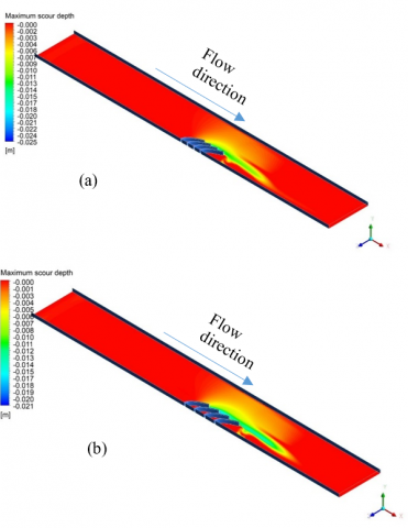
Figure 6. Maximum scour depth contour-lines of 4- groynes with constant spacing (a) S=0.5L, (b) S=0.75L, (c) S=1L, (d) S=1.5L
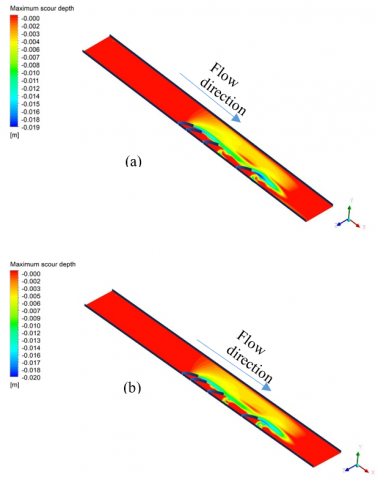
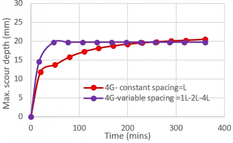
To find the effect of variable spacing between parabola-shaped 4-groynes on the maximum scour depth, two CFD models with spacing between them arranged as S=0.75L-1.5L-3L and S=L-2L-4L respectively have been done as shown in Figure 7. By compare the results, it can be clearly seen from Figure 8 that at the initial stage of scouring around the groynes the rate of increase in the maximum scour depth in the case of variable spacing is greater compared with the case of constant spacing for parabola-shaped groynes. However, at the equilibrium stage the scour rate with variable spacing between the groynes became more stable than in the constant spacing case.
Figure 7. Maximum scour depth contour-lines of 4- groynes with variable spacing (a) S=0.75L-1.5L-3L, (b) S=L-2L-4L
Figure 8. Maximum scour depth profile 4-groynes with different spacing
4.2 Effect of different shape groynes arranged in a row on the maximum scour depth
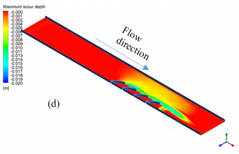
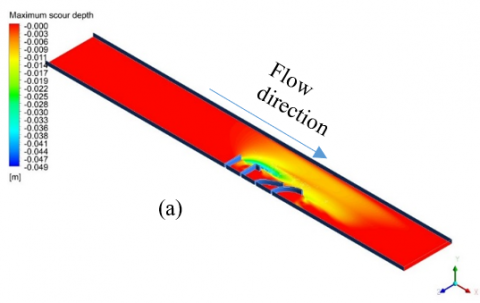
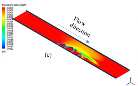
Another study has been done to investigate the best arrangement for groynes with different shapes located in one open channel, Figure 9 (a) shows that arrangement starting with I section is the worst design because it produces higher scour depth. Vice Verica the arrangement of groynes started with parabola-shaped is the best from practical side as shown in Figure 9 (b). Also, it can be clearly seen that the I section should be avoided to located at the end of the arrangement as shown in Figure 9 (c). As a result, for multi-groynes, have different shapes, arranged in a row in a river, groynes with smooth angles such as parabola and quadrant shapes recommended to constructed in the front of sharp angles groynes such as I and L shapes since this arrangement reduce the scour depth around groynes.
Figure 9. Maximum scour depth contour-lines of 4-groynes with different shapes and constant
This study has been carried out to study the effect of groynes on the maximum scour depth using a computational fluid dynamic technique (CFD). The first part of this study has been done to validate the CFD model with previous experimental studies, the result of numerical model showed a good agreement with the results of the scouring depths measured in those studies. Secondly, the implemented investigation of the effect of spacing variation along the open channel clearly showed that the best spacing between the groynes which results minimum scour depth happened when the spacing between groynes is equal to the length of the groyne itself and there is no mentioned effect if the spacing is greater than this magnitude. Finally, the effect of the shape of the groynes which has been also investigated and it was found that when multi-groynes arranged respectively in an open channel, the parabola shape is the best shape to start with this arrangement, while the starting with L shape groynes produced the higher value of maximum depth.
[1] Ibrahim, M.M. (2012). Experimental study to investigate the flow pattern associated to angled groins. Journal of American Science, 8(10): 313-322.
[2] Vaghefi, M., Shakerdargah, M., Fiouz, A.R., Akbari, M. (2014). Numerical investigation of the effect of Froude number on flow pattern around a single T-shaped spur dike in a bend channel. International Journal of Engineering Research, 3(5): 351-355. http://dx.doi.org/10.17950/ijer/v3s5/515
[3] Oberhagemann, K., Haque, A.A., Thompson, A. (2020). A century of riverbank protection and river training in Bangladesh. Water, 12(11): 3018. http://dx.doi.org/10.3390/w12113018
[4] Kang, J., Yeo, H., Kim, S. (2011). Experimental study on the flow characteristics around the refraction groyne. Engineering, 3(8): 842. http://dx.doi.org/10.4236/eng.2011.38103
[5] Möws, R., Koll, K. (2019). Roughness effect of submerged groyne fields with varying length, groyne distance, and groyne types. Water, 11(6): 1253. http://dx.doi.org/10.3390/w11061253
[6] Dawood, A.M. (2013). A study of scour and deposition around groynes. Unpublished M. Sc. Thesis, Civil Department, Faculty of Engineering, University of Kufa, Iraq.
[7] Al-Yassiry, H.H. (2015). Investigation of local scour around curved groynes. unpublished M. Sc. Thesis, Civil Department, Faculty of Engineering, University of Kufa, Iraq.
[8] Dehghani, A.A., Azamathulla, H.M., Najafi, S.H., Ayyoubzadeh, S.A. (2013). Local scouring around L-head groynes. Journal of hydrology, 504: 125-131. http://dx.doi.org/10.1016/j.jhydrol.2013.09.020
[9] Majeed, H.Q. (2017). Scour around Complex Shape Bridge Piers in a River. Doctoral dissertation, University of Leeds, West Yorkshire, United Kingdom.
[10] Majeed, H.Q., Abed, B.S., Shamkhi, M.S. (2021). CFD simulation for the operation effect of gates openings of al-hay regulator on the local erosion. Journal of Engineering Science and Technology, 16(2): 1098-1109.