Matteo Malavasi* | Luca Cattani | Fabio Bozzoli | Sara Rainieri
© 2022 IIETA. This article is published by IIETA and is licensed under the CC BY 4.0 license (http://creativecommons.org/licenses/by/4.0/).
OPEN ACCESS
The grape must temperature management in a fermenter tank is fundamental to guaranty a high-quality wine. The fermentation is an exothermic process and a good cooling system in fermenter tanks is required. However, for reducing costs and increasing the efficiency of the cooling operation, a passive device based on the heat pipe technology was proposed. Since its thermal sizing must necessarily be accurate to allow a correct temperature of the product during fermentation, in this paper a thermal model of the proposed device was proposed and experimentally validated.
thermosyphon heat pipe, fermentation oenological production, food industry
The control of the temperature in a fermenter tank is fundamental to guaranty a high-quality final product, especially in winemaking processes, since the temperature is one of the most important parameters influencing the alcoholic fermentation [1]. The fermentation is an exothermic process and a good cooling system in fermenter tanks is required for keeping the temperature inside an optimal interval. To control the temperature inside the fermentation tanks, the most adopted solutions are represented by an external cooling jacket in which cold water flows [2]. This system is based on the circulation of a cooling fluid that represents a source of energy consumption and a cost for the producer. Therefore, its optimization is aimed at reducing energy consumption and could consequently contribute to a decrease in production costs and an increase in the energy efficiency of the entire production phase. Moreover, the cooling method based on external cooling jacket presents problems related to a non-uniformity of temperature inside the product that could negatively impact on the fermentation process.
A first prototype of a semi-passive alternative solution for controlling the temperature during wine making fermentation is proposed with a double aim: increase the uniformity of temperature inside the product during fermentation and reduce the energy consumption of this phase. Heat pipes have been identified as a viable solution for this purpose since they are two-phase passive heat transfer devices with a high heat transfer capability, efficient thermal control, adaptability, simplicity of production, and very low cost [3].
Usually, a common heat pipe is composed by an evacuated metal tube filled with a certain amount of working fluid in saturation condition. One extremity of the pipe works as the evaporator and the other one works as condenser. The evaporator being in contact with the object to be cooled down, receives the heat from it. Inside the evaporator, working fluid than starts to vaporize due to the heat input. The vapor starts to move towards the condenser zone thanks differential pressure between the two zones, passing by the inner core of the pipe. Once in the condenser, the vapor condensates releasing latent heat to a could source [4, 5]. In a so called “thermosyphon heat pipe”, the condensate comes back to the evaporator that is located at the bottom of the device, thank the gravity force.
These devices demonstrated to have a great potential in terms of heat transfer and achievable energy consumption reduction in many industrial fields such as electronical [6], including the food one [7-9].
For this reason, an ideal device based on the heat pipe technology was previously studied for investigating the feasibility of its application in a wine fermenter tank [10]. Thanks to the positive results achieved, in this paper the authors focused on the development of an effective tool for the thermal sizing of this kind of device, since fermentation conditions differ from wine to wine and from producer to producer. In particular, a model of the thermal behaviour of heat pipe in the fermenter tank, based on a resistance network, was proposed and validated with an experimental test in which a fermentation process was simulated inside a small stainless-steel tank with the thermosyphon heat pipe for the product temperature control.
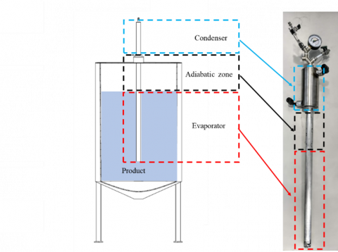
Figure 1 shows the application of the thermosyphon heat pipe to a fermenter for the wine industry. The device is immersed in its lower part, which we will call the "evaporator", while it protrudes from the fermenter at the top with its part, we will call the "condenser". The rest of its length constitutes the 'adiabatic zone'.
Figure 1. Schematic representation of the thermosyphon applied to the fermenter tank for wine industry and identification of its zones
When designing a thermosyphon heat pipe, one of the fundamental parameters for its thermal dimensioning is the so-called equivalent thermal resistance [11], defined as follows:
$R_{e q}=\frac{T_e-T_C}{Q}$ (1)
where, Te and Tc are the temperature at the evaporator and the temperature at the condenser, respectively. Q is the power input at the evaporator.
The use of a heat pipe in a fermenter, with the aim of regulating the temperature of the must during the fermentation process, is subject to non-negligible operational constraints dictated by the operational requirements of the fermentation phase itself. These constraints are necessary to guarantee the success of the production process and, consequently, the quality of the final product.
In specific, the ambient temperature of the wine cellar is defined by the weather, by the season and by the location of the building where the fermentation takes place. It can therefore be said that this parameter tends to be imposed depending on the production conditions to which the process is subjected and can hardly be managed and varied significantly. For this reason, the ambient temperature, and thus the temperature at which the heat pipe condenser will be located (Tc), is to be considered as constrained. Moreover, the heat released from the fermentation is defined by the amount of glucose inside the grape must and the kinetics of the yeast metabolism during the entire process. It may be subject to slight variations during the time span of fermentation, but generally this parameter is also to be regarded as bound to non-modifiable characteristics of the process. For this reason, also Q is to be considered as constrained. Finally, the temperature at the evaporator Te, and so the temperature corresponding to the one of the fermenting products, is of great importance in order to ensure optimal metabolic activity of the yeast involved in this biochemical reaction. For this reason, it cannot be considered as a free parameter and therefore it is to be regarded as constrained according to the production process characteristics considered. In specific, this temperature is selected by the producer depending on the type of wine produced and on the organoleptic features wanted in the final product.
It is therefore clear that, considering the parameters Q and Tc as fixed by the process conditions, the way to obtain a desired product temperature (Te), is to work on the only parameter not related to the process: Req. It is a function of the construction characteristics of the heat pipe and function of the power Q, and for this reason it must be deeply investigated in order to understand how to act to design it. For this purpose, a thermal model of the thermosyphon heat pipe applied to the wine fermentation was built as follow.
(a)
(b)
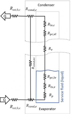
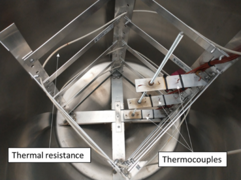
Figure 2. (a) Complete resistor network, (b) inside picture of the fermentation tank used for simulating the fermentation for the validation of the model
Figure 2 (a) shows the contribution of the different thermal resistances and their connection. Considering the heat entering the heat pipe, it is possible to schematise its path through a succession of thermal resistances, for creating a model describing the operation of the thermosyphon. These resistances can be expressed as follow:
-External convective resistance at the evaporator (Rext,h,e):
It is the resistance due to the external fluid convection at the evaporator. This value can be expressed ad follow:
$R_{e x t, h, e}=\frac{1}{h_{e x t, e} \,\,\,A_e}$ (2)
where, hex,e and Ae are respectively the convection coefficient of water at the evaporator and the exchange area.
-Wall conduction resistance at the evaporator (Rcond,e):
It is the resistance due to the wall layer of the heat pipe considering the radial direction. It can be calculated as follow:
$R_{\text {cond }, e}=\frac{\ln \left(\frac{r_{e x t}}{r_{i n}}\right)}{2 \pi \lambda l_e}$ (3)
where, rex and rin are the outer and inner radius, λ is the conductivity of the material, and le the length of the evaporator.
-Wall axial conduction resistance (Rcond,ax):
It is the resistance for the heat flow in the axial direction of the heat pipe through the wall, and can be expressed as follow:
$R_{\text {cond,ax }}=\frac{l_{H P}}{\pi \lambda\left(r_{e x t}^2-r_{i n t}^2\right)}$ (4)
where, lHP is the length of the thermosyphon heat pipe. It is usually three orders of magnitude greater than the radial resistance, so the amount of heat that tends to flow axially through the wall of the heat pipe can be neglected. Almost all of the heat power flows radially through the surface and heats the internal fluid. In fact, this thermal resistance is positioned parallelly to all the successive ones in Figure 2 (a) (in series with each other) that characterise the inner part of heat pipe.
-Pool boiling resistance (Rp):
It represents the boiling resistance of the fluid in the thermosyphon evaporator. The heat flow, after passing through the wall layer, enters the evaporator, where it warms up the liquid held in a small bath at the bottom of the device. For this resistance, it is possible to use a formulation like those used for convection, as follow:
$R_p=\frac{1}{h_{i n t} A_{i n t}}$ (5)
where, the subscript int denotes the values inside the heat pipe in the pool area.
-Thermal Resistance of the Evaporator Film (Rlv,e):
Once passed the aluminium wall, the heat flux invests the liquid fluid either on the base in the pool or, if the pool does not cover the entire height of the evaporator (as in this case), the film layer of condensed liquid that is descending from the cold side towards the hot side. Considering the fluid's properties and the film thickness, this resistance can be expressed as follow [12]:
$R_{l v, e}=\frac{0.235 q_e^{1 / 3}}{D_i^{4 / 3} g^{1 / 3} \,\,\,l_e\left(\frac{h_{l v}\,\,\, \lambda_l^3 \,\,\,\rho_l^2}{\mu_l}\right)^{1 / 3}}$ (6)
where, qe is the power entering the evaporator, hlv is the latent heat, λl is the conductivity of the liquid, ρl its density and μl its viscosity.
-Phase change resistance (Rpc,lv and Rpc,vl):
After passing through the liquid film, the heat flow encounters another resistance caused by the liquid-to-vapour phase transition interface. This contribution occurs in an identical manner both passing from liquid to vapour in the evaporator and, in the opposite way, passing from vapour to liquid inside the condenser. Usually, these two resistances are not considered because they are extremely low, on the order of 10-5℃W-1. Therefore, these two contributions can be considered negligible.
-Thermal Resistance of flowing vapour (Rv):
The movement of the vapour creates an extremely low resistance, of the order of 10-8℃ W-1, and therefore also this contribution is eliminated from the final balance.
-Thermal Resistance of the Condenser Film (Rlv,c):
It is due to the thickness of the film of the condensate on the internal wall of the condenser. For this case too, it can be used the empirical formula written in Eq. (6), substituting the value of $q_e$ with the power provided to the condenser qc, that in this case it was considered to be equivalent to the one at the evaporator:
$R_{l v, c}=\frac{0.235 q_c^{1 / 3}}{D_i^{4 / 3} g^{1 / 3} \,\,\,l_e\left(\frac{h_{l v} \,\,\lambda_l^3 \,\,\,\rho_l^2}{\mu_l}\right)^{1 / 3}}$ (7)
-Wall conduction resistance at the condenser (Rcond,c):
It is the same resistance exposed in Eq. (3) but considering the geometrical dimension of the condenser.
-External convective resistance at the condenser (Rext,h,c):
It is the final resistance of the model, and it represents the resistance at the external side of the condenser. In this case it can be figured like a convective resistance, as follow:
$R_{e x t, h, c}=\frac{1}{h_{e x t, c} \,\,\,A_{e x t, c}}$ (8)
where, hex,c and Ac are the convective coefficient of the fluid on the external side of the condenser and the external heat exchange area of the condenser, respectively.
Finally, it is possible to write the final balance equation of the model, using Eqns. (2-8), excluding the contributes identified as negligible (i.e., Rcond,ax, Rpc,lv, Rpc,vl, Rv). The model, in its general form, can be written as follow:
$R_{e q}=R_{e x t, h, e}+R_{\text {cond }, e}+R_p+R_{l v, e}+R_{l v, c}+R_{\text {cond }, c}+R_{e x t, h, c}$ (9)
3.1 Experimental setup and conditions
For the validation of the thermal model, wine fermentation conditions were simulated inside a stainless-steel tank: 100 l of grape must with a glucose concentration of 300 g/l were considered as fermenting substrate, that correspond to 1.66 mol/l. During the alcoholic fermentation, each mole of fermented glucose generates heat of about 106 kJ. The kinetics of metabolism of the yeasts involved in a week-long fermentation is more concentrated in the first 48 hours and it is possible to state that the 80%-90% of the heat is generated in this period. For that reason, it is possible to state that 100 W is the power generated by the fermentation in this specific conditions. However, considering the dispersion of the tank to the environment, it is possible to state that only a proportion of 65 W of the power generated by the fermentation is handled by the thermosyphon heat pipe [9].
For the simulation, water was used as fermenting substrate and the power Q of 100 W was provided to the water inside the tank by means a thermal wire resistance. During the fermenting simulation, the water inside the tank was mixed by a stirring system for simulating the effect of the pumping over of the grape must that is commonly applied to a real fermentation.
For the control of the fermentation temperature of the product inside the tank, a thermosyphon heat pipe in aluminium with a cylindrical shape was made. It is characterised by an external diameter of 0.03 m, an internal one of 0.02 m and a length of 0.8 m. Once it was inserted in the fermenter, the length of the evaporator section (the part immersed in the product) resulted of 0.4 m, while the length of the condenser area (the part outside the fermenter) resulted of 0.2 m. Finally, it was filled with R134a refrigerant fluid with a filling ratio of about 20%. The condenser of the heat pipe was kept at constant temperature using an external cooling jacket in which flowed cold water at 18℃. Using a sufficient flow rate, at the condenser it was possible to obtain a temperature-imposed condition. 18℃ is a representative value of the ambient temperature that can be found in a fermentation cellar, and consequently it could be considered the temperature at which the device condenser might be working in oenological field.
Inside the tank an equally distributed network of twelve type-T thermocouple was created to measure the temperature of the product (Figure 2 (b)). Moreover, the inlet and the outlet temperature of the cooling jacket of the condenser was monitored using 4 thermocouples. Temperature signals were read by a data acquisition system (National Instrument NI CDAQ chassis + 3 NI 9213 C Series modules) connected to an ice point reference, type KAYE K170-274 50C.
The test was performed until the reaching of the steady state condition of the water inside the tank.
With this experiment it was possible to obtain an experimental value of the Req for the thermosyphon heat pipe for the comparison with the one calculated with the proposed model to allow the validation of the model itself.
3.2 Experimental estimation of the equivalent resistance of the thermosyphon heat pipe
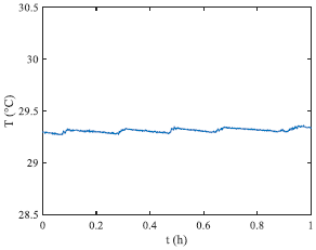
In Figure 3 it is possible to observe the average temperature inside the product in steady state condition, and it is possible to observe that it is stable around 29.35℃. This temperature corresponds to the temperature of the evaporator Te and it is possible to substitute it inside Eq. (1) together with the real temperature of the condenser Tc=18℃ and the real value of Q= 65W, obtaining a value for the experimental Req of 1.75∙10-1℃ W-1.
Figure 3. Average temperature of the product inside the fermenter tank
3.3 Model application
By the proposed numerical model, the equivalent resistance of the thermosyphon heat pipe under investigation is calculated, starting from the computation of the values of the different thermal resistances.
The value of the external area of the thermosyphon heat pipe evaporator is of 0.38 m2. It is substituted to the Ae term in Eq. (2), and it was a forced convection condition for the water outside the evaporator due to the stirring system (hext,e can be assumed equal to 500 Wm-2K-1). In this way, Rex,hs resulted 0.053℃ W-1.
Substituting the geometrical values in Eq. (3) and considering the thermal conductivity of the aluminium of about 210 Wm-1K-1, the parameter Rcond,e and Rcond,c result in the order of magnitude of 10-4℃ W-1. For this reason, in this case, they can be considered negligible.
In Eq. (4) it is possible to assume a value of 105 Wm-2K-1 for $h_{\text {int }}$ and, substituting all the geometrical values of the thermosyphon heat pipe, it is possible to state that Rp is equal to 3.3∙10-2℃ W-1.
Considering hlv=173.09 KJ kg-1, ρl=1187 kg m-3 and λl=0.079 W m-1 K-1 of the refrigerant R134a at the temperature of the evaporator, and the geometrical values of the evaporator section, it is possible to obtain a value of Rlv,e equal to 2.4∙10-2℃ W-1. In this case, to simplify the model, the surface area wetted by the pool boiling was neglected, considering the entire internal area of the evaporator as the film surface. Moreover,
Repeating the passages used for calculating Rlv,e but using and the geometrical values of the condenser, it is possible to obtain a value of Rlv,c, that in this case is equal to 4.8∙10-2℃ W-1.
Since the condenser is kept at a constant temperature of 18°C by its cooling jacket, it is possible to state that in this case it is in temperature-imposed condition and, for this reason, its thermal resistance can be neglected.
Substituting in Eq. (9) the values obtained in the previous steps, and excluding the ones neglected during the calculation, it is possible to compute the theorical value of Req, that corresponds to 1.65∙10-1℃ W-1.
This value is in accordance with the one obtained experimentally. In fact, the two values differ by 5.7% and, for this reason, the model can be considered quite accurate for the estimation of the equivalent resistance of a thermosyphon heat pipe used in these conditions and it is possible to state that it is validated.
In this paper a model for calculating the thermal behaviour of a thermosyphon heat pipe applied to a fermenter tank for wine production was developed. Since the temperature of the product is of fundamental importance during the fermentation phase, a precise thermal sizing of this device is needed. The model proposed was based on a network of resistances that describes the operation of the device. The model was validated by means of an experimental test that involved a thermosyphon heat pipe installed in a small-scale fermenter of stainless steel, in which the conditions of a fermenting process were reproduced. During the experiment, it was possible to calculate the experimental thermal equivalent resistance and successively it was compared to the one obtained with the theoretical model. The two values differ by only the 5.7%, confirming the validation of the model and its suitability for the thermal sizing of these kind of devices in these specific conditions.
This work was partially supported by the Emilia-Romagna Region (Piano triennale alte competenze per la ricerca, il trasferimento tecnologico POR FSE 2014/2020). The authors would like to acknowledge the European Space Agency (ESA) support through grant 4000128640/19/NL/PG/pt, ESA MAP project TOPDESS.
The authors would also like to thank MBS S.r.l. for its great technical support in the realisation of the experimental setup used for the tests performed in this project.
Finally, the authors thank student Manuel Bonetta for the support in the experimental tests.
|
Symbols |
Quantity |
SI Unit |
|
|
A |
Heat transfer surface area |
m2 |
|
|
D |
Diameter |
m |
|
|
g |
Gravity acceleration |
m/s2 |
|
|
h |
Convective heat transfer coefficient |
W/m2∙K |
|
|
m |
Mass |
Kg |
|
|
Q |
Heat transfer rate |
W |
|
|
R |
Thermal resistance |
°C/W |
|
|
r |
Radius |
m |
|
|
T |
Temperature |
K |
|
|
t |
Time |
s |
|
|
$\lambda$ |
Thermal conducivity |
W/m∙K |
|
|
$\rho$ |
Density |
Kg/m3 |
|
|
$\mu_l$ |
Dinamic viscosity |
Pa∙s |
|
|
Subscripts, superscripts |
|||
|
ax |
Axial |
||
|
c |
Condenser |
||
|
h |
Convective |
||
|
THP |
Thermosyphon heat pipe |
||
|
e |
Evaporator |
||
|
eq |
Equivalent |
||
|
ex |
External |
||
|
int |
Internal |
||
|
l |
Liquid |
||
|
lv |
Liquid-vapor |
||
|
vl |
Vapor-liquid |
||
|
p |
Pool boiling |
||
|
pc |
Phase change |
||
|
v |
Vapor |
||
[1] Colombié, S., Malherbe, S., Sablayrolles, J.M. (2007). Modeling of heat transfer in tanks during wine-making fermentation. Food Control, 18(8): 953-960. https://doi.org/10.1016/j.foodcont.2006.05.016
[2] Zenteno, M.I., Pérez-Correa, J.R., Gelmi, C.A., Agosin, E. (2010). Modeling temperature gradients in wine fermentation tanks. Journal of Food Engineering, 99(1): 40-48. https://doi.org/10.1016/j.jfoodeng.2010.01.033
[3] Jowitt, R. (1984). Fermentation and biochemical engineering handbook — Principles, process design and equipmentEdited by Henry C. Vogel. Noyes Publications, New Jersey. 1983. 440 pp. + xv. Price: US$64. Journal of Food Engineering, 3(2): 162-163. http://linkinghub.elsevier.com/retrieve/pii/0260877484900372.
[4] Huminic, G., Huminic, A., Morjan, I., Dumitrache, F. (2011). Experimental study of the thermal performance of thermosyphon heat pipe using iron oxide nanoparticles. International Journal of Heat and Mass Transfer, 54(1-3): 656-661. https://doi.org/10.1016/j.ijheatmasstransfer.2010.09.005
[5] Bahmanabadi, A., Faegh, M., Shafii, M.B. (2020). Experimental examination of utilizing novel radially grooved surfaces in the evaporator of a thermosyphon heat pipe. Applied Thermal Engineering, 169: 114975. https://doi.org/10.1016/j.applthermaleng.2020.114975
[6] Kannan, K.G., Kamatchi, R., Venkatajalapathi, T., Krishnan, A.S. (2018). Enhanced heat transfer by thermosyphon method in electronic devices. International Journal of Heat and Technology, 36(1): 339-343. https://doi.org/10.18280/ijht.360145
[7] Srimuang, W., Amatachaya, P. (2012). A review of the applications of heat pipe heat exchangers for heat recovery. Renewable and Sustainable Energy Reviews, 16(6): 4303-4315. https://doi.org/10.1016/j.rser.2012.03.030
[8] Pipatpaiboon, N., Parametthanuwat, T., Bhuwakietkumjohn, N., Rittidech, S., Sichamnan, S. (2022). Applications of heart shaped glass spoon loop oscillating heat pipe (HSGS/LOHP) for making coffee stirrer. International Journal of Heat and Technology, 40(1): 258-266. https://doi.org/10.18280/ijht.400130
[9] Ramezanizadeh, M., Nazari, M.A., Ahmadi, M.H., Lorenzini, G., Kumar, R., Jilte, R. (2018). A review on the solar applications of thermosyphons. Mathematical Modelling of Engineering Problems, 5(4): 275-280. https://doi.org/10.18280/mmep.050401
[10] Malavasi, M., Cattani, L., Bozzoli, F., Rainieri, S. (2022). Development of an innovative temperature control system in a fermenter: Application to the case of the wine industry. In Journal of Physics: Conference Series, 2177(1): 012036. http://dx.doi.org/10.1088/1742-6596/2177/1/012036
[11] Driss A., Maalej S., Chouat I., Zaghdoudi M.C. (2019). Experimental investigation on the thermal performance of a heat pipe-based cooling system. Mathematical Modelling of Engineering Problems, 6(2): 217-228. https://doi.org/10.18280/mmep.060209
[12] Mantelli, M.B.H. (2021). Thermosyphons and Heat Pipes: Theory and Applications.