Omar Nameer Mohammed Salim | Ammar Hussein Mutlag | Salah A. Adnan* | Siraj Qays Mahdi
© 2022 IIETA. This article is published by IIETA and is licensed under the CC BY 4.0 license (http://creativecommons.org/licenses/by/4.0/).
OPEN ACCESS
Optical communication systems (OCSs) have become increasingly important in recent decades because these systems provide high-speed, reasonable cost connectivity. One of the most important parts of OCSs is their optical source, where the laser diode (LD) is the most widely used source type. The devices used to settle and control the laser diode temperature are vital to the operation of OCSs. This paper proposes an efficient controlled cooling system for optical communication LDs using a thermoelectric cooler controlled by an Arduino Uno microcontroller. To accomplish precise and fast control of LD temperature, a proportional integral derivatives algorithm is used. The control program was run on the Arduino Uno board. Analysis of the proposed system model was first performed using a simulation in MATLAB. Robust results were obtained, showing that the LD temperature decreased from 70°C to 25°C in 170 seconds with stable system performance across 6,000 seconds of operation. A second analysis was conducted by constructing the proposed controlled cooling system and implementing real-time testing of its performance. The real-time implementation shows that the proposed system decreases the LD temperature from 71°C to the setpoint temperature (25°C) in 176 seconds. This finding shows a fast, smooth system response with only negligible overshooting and demonstrates the stability of the system performance across 6,000 seconds of testing.
controlled cooling system, laser diode, optical communication, PID controller, TEC
Optical communications began with the use of light to convey information and news to the human eye [1]. As technology progressed, transmitting and receiving signals has become possible over longer distances, with more secure methods of data encryption. The development of modern optical communication systems (OCSs) began in the 1970s with devices operating in the visible and infrared wavelength ranges [2]. An OCS has a bandwidth 104 times greater than that of radio frequency (RF) and microwave communication systems, allowing many users to communicate at the same time [3]. Communication tasks are performed in an OCS by utilizing three phases: data transmission, channel characterisation, and data receipt [4]. The primary role of the transmitter is to convert electrical signals into optical signals. Optical transmitters frequently make use of laser diode (LD) devices [5]. The channel is the medium in which the optical signals travel — at present, there are two major types. The first is the fibre optic channel, where optical signals are transmitted in a flexible and transparent medium made of extremely fine silica glass or high-quality polymer; the second is the free-space optical (FSO) channel where optical signals are transmitted through an air medium [6, 7]. Optical receivers are primarily responsible for the conversion of optical signals into electrical signals [3]. The photodetector component of an optical receiver detects the optical signal and converts it to electrical current, where the current value is proportional to the number of incident photons [2, 6].
When lasers were invented, optical communication was becoming increasingly accessible and affordable, however, optical communication via laser radiation was hampered by several difficulties such as atmospheric obstacles in FSO communication, optical fibre losses, laser diode (LD) limitations, and photodetector precision [8, 9]. An LD is a compact and rigid optical source that may be utilized in optical communication; however, changes in the LD’s output wavelengths and power will result in performance limits [10], [10]. The operating temperature of the LD has a significant impact on its optical efficiency [1]. An LD's working temperature is determined by the temperature of its surroundings and the junction temperatures [11, 12]. Therefore, controlling LD temperature is a crucial factor in communication systems for achieving maximum stability in the emitted wavelength and optical power [13].
Analogue circuits, proportional integral derivatives (PID), and Artificial Intelligence (AI) have all been used in temperature control systems [9, 11] A real-time PID temperature controlling system is proposed in this work. A PID control method was chosen in this study because a real-time PID regulator is a controller that continuously adjusts to find the optimal constants as required. Furthermore, based on the overflow removal capability belted in the PID algorithm, it is possible to respond quickly, avoid overflow, and additionally adjust the controller's hysteresis [14-17]. In this work, the LD temperature needs to be recorded and adjusted instantly with high precision while avoiding temperature overshooting due to the LD’s high sensitivity. However, temperature errors will affect the performance and accuracy of the OCS; thus, a real-time PID control system is the optimum choice. This paper contains five sections, where section two discusses the theoretical principles of the thermoelectric cooler (TEC) and PID controller. The design of the proposed controlled cooling system is presented in section three. The results are discussed in detail in section four, and section five contains the conclusions of the study.
The first steps involved in designing the controlled cooling system are selecting the cooling method and the control method. The TEC is proposed in this work as a cooler device. Some of the advantageous TEC features for use in this proposed system include its compact size, controllability, low cost, and long life. As noted above, the PID method was chosen in this project to control the cooling system.
2.1 Thermoelectric cooler
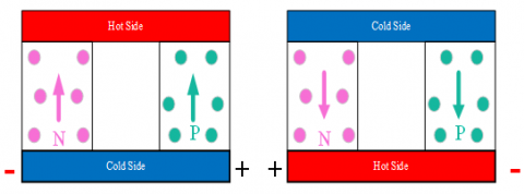
TEC module is a device made up of two ceramic plates sandwiching thermoelectric couples of P-type and N-type semiconductor material [18]. In electronic system applications where cycling or stabilizing of operational temperatures is required, the TEC module is the best choice [19]. TECs operate according to the phenomenon of temperature change between two contacting plates of metals or semiconductors that occurs when a direct electrical current passes via a contact region. One side of the TEC will be cold, and the other side will be hot; this phenomenon is known as the Peltier effect and is shown in Figure 1 [20]. One side of the TEC becomes hot due to electrons moving from the N-material to the lower energy P-material and releasing energy; similarly, the other side becomes cold due to the energy absorbed by electrons moving from the P-material to the higher energy level N-material [21]. The TEC’s hot and cold sides can be specified according to the direction and amount of current flow, thus, TEC temperatures can be controlled by controlling current flow.
Figure 1. Thermoelectric Cooler device
2.2 PID controller
The PID control approach is one of the most widely used in the industry, where it is used in even the most complicated industrial control systems [21]. The PID control process is based on a feedback circle to control process variables (PVs), where each PV is a system quantity that is measured by a sensor and controlled to match a desired set output point (SP), as shown in Figure 2 [22]. The error in each feedback circle is generated due to the difference between the PV value and SP value [23]. This error will be used as a reference by the PID controller to generate a control signal [24, 25]. The control signal is transferred to an actuator, which is responsible for modifying the system variables to minimize the errors between PV and SP in the next feedback circle until said errors become zero [20]. Each one of the PID controller terms (KP, KI, and KD) has a specific role and characteristics, described below [26].
Figure 2. Structure of PID controller
The proportion term (KP) deals with the present errors and aims to achieve a control signal proportionate to the difference between SP and PV in the present cycle [26]. A steady-state error is always present in the system because the controller is unbalanced to activate PV rapidly enough to achieve the SP value, thus there will be oscillations and overshoots if the KP term is too large [24]. Therefore, most control systems will need more than a proportional controller, so the proportional term is usually followed by an integral term, making the controller a PI-controller [27].
The integral term (KI) takes into consideration every error that has occurred in the system from the onset of system operation to the current stage in the process [26]. It analyses the error history up to that moment, thus, KI is a very important term in PID systems [28]. The KI term seeks to strike a balance between the period that PV spends below and above the setpoint, i.e. if the PV runs at 95% of the SP for 20 seconds, the KI term will raise the PV to 105% for the next 20 seconds to identify the difference [28]. Accordingly, overshooting could occur, which is potentially very harmful to the sensitive controlling system [14].
Hence, the third term used in a PID is KD. At each point, the KD term takes the derivative of a PV [24]; as a result, it forecasts how the PID loop will operate in the future. Thus, KD is used to see how the PV changes without exceeding the SP [20]. As the PV value gets closer to the SP, it stabilises at the SP value without overshooting or with only minimal overshooting. The output control signal of the PID controller shown in Figure 2 can be expressed as Eq. (1) [26].
$u(t)=K_{\mathrm{P}} e(t)+K_{\mathrm{I}} \int e(t) d t+K_{\mathrm{D}} \frac{\partial e(t)}{\partial t}$ (1)
where, u(t) is the output control signal, e(t) is the error value, KP is the proportional term, KI is the integral term, and KD is the derivative term. A Laplace transform is used to obtain the PID controller transfer function, as shown in Eq. (2) [26].
$U(s)=K_{\mathrm{P}}+\frac{K_{\mathrm{I}}}{s}+K_{D} s$ (2)
The structure of the proposed optical communication LD cooling system enables the control program to interact with the hardware parts of the system simultaneously, thus achieving a real-time controlled cooling system. A schematic of the proposed system hardware is shown in Figure 3.
3.1 Proposed system hardware
As illustrated in Figure 3, the main hardware components of the proposed system are the microcontroller, temperature sensor, LD holder, and cooling system. These hardware parts operate according to the instructions of the control program uploaded into the microcontroller.
3.1.1 Microcontroller
Microcontrollers are integrated circuit devices used to control other electronic systems through various peripherals such as a microprocessor unit and memory [29]. The Arduino Uno platform proposed in this work is a microcontroller unit, where the microcontroller and software are both parts of the Arduino device [30]. The Arduino board was chosen over other microcontrollers because it can be used without being connected to a PC, making it more compact and flexible. Furthermore, it can drive all parts of the hardware required for the proposed system which makes it more versatile [31].
The Arduino Uno is based on the ATmega328P microcontroller [30]. It has a 16 MHz crystal oscillator, six analogue input pins, 14 pins for digital inputs or outputs, where PWM outputs can be obtained from six of these pins, a power connection, and a USB connection used to connect the board to a computer and upload programs [31]. The Integrated Development Environment platform used for Arduino programming simplifies building and developing control programs [32].
3.1.2 Temperature sensor
Two K-type Thermocouple temperature sensors with a detecting range of -20 to 500℃ and a resolution of 0.25℃ are used in this proposed project [33]. One of these temperature sensors is connected to the LD to detect its temperature instantly, while the other is connected to the hot side of the TEC to sense its temperature. Both sensors are connected to the Arduino board through a MAX66750 module [33].
3.1.3 Laser diode holder
The laser diode used in the proposed system is an OCLARO HL63163DG model (633 nm, 100 Mw, and ϕ 5.6 mm). Since this LD is small, an LD holder was designed and fabricated to be used in this system. Aluminium alloy 6060 was used to fabricate the LD holder; this material has a favourable specification, including a strong structure, malleability, and good thermal conductivity which makes it ideal to be used as an LD heat sink holder. The dimensions of the fabricated LD holder were L=40 mm, W=44 mm, and H=20 mm — these dimensions were chosen to matched the dimensions of the TEC used in this study to achieve maximum heat exchange between the LD and TEC.
3.1.4 Cooling system
The proposed cooling system comprises two main parts which are the TEC cooling and the liquid radiator cooler. The TEC1-12706 is used in this project as a main cooling unit for the LD, where the cooling module’s dimensions are L=40 mm, W=40 mm, and H=3.8 mm. This unit operates at Vmax= 16 V and I max= 6 A, with a maximum cooling capacity equal to 66.7 watts on the cooled side of the TEC. The TEC module is operated by a controlling signal from the Arduino board through a MOSFET module. The TEC control signal is set to the current value that will pass through the TEC module, which in turn defines the cooling capacity of the TEC.
The main function of the liquid radiator cooler is to cool the hot side of TEC. The temperature difference between the cooled and hot sides of the TEC must be maintained within a certain range as specified by the design of the cooling system. Accordingly, the hot side of TEC must be cooled to within a certain temperature range to maintain a regular temperature difference between the two sides of the TEC.
The liquid radiator cooler consists of three parts. The first is an aluminium liquid cooling heatsink block (L=40 mm, W=40 mm, and H=12 mm) attached to the hot side of the TEC. The second part is a liquid pump connected to the first part by a flexible PVC pipe, which has a flow rate of up to 15 litre/min, where the flow rate is controlled by a control signal from the Arduino board through a MOSFET module. The third part is an aluminium liquid radiator connected to a liquid pump that has dimensions of L=160 mm, W=140 mm, and H=38 mm.
3.2 Proposed system program
The program responsible for controlling the operation of the proposed system is shown in Figure 4. The PID algorithm was first designed using MATLAB; the values of KP, KI, and KD were also found using MATLAB. The determined values of the KP, KI, and KD terms were used in the controlling program, which was designed and written using the Arduino integrated development environment platform and uploaded to the Arduino Uno board.
The control program was designed to record and monitor the LD temperature and the TEC hot side temperature, with the temperatures detected by a K-type temperature sensor and the values transferred to the Arduino board by a MAX66750 module. The control program then calculates the error between the setpoint temperature and the real LD temperature. According to this error value, the program calculates the output control signal value as a PWM signal whose value lies between 0 and 255. If the output is less than 0, the value of the output control signal is set to 0; similarly, if the output is greater than 255, the value of the output control signal is set to 255. These control signals are transferred to the TEC to set its operating current to control the cooling temperature and transferred to the water pump to set its operating voltage to control the cooling liquid flow rate. The proposed controlling procedure ensures that the temperature of the LD is stable and maintained within the limits of the desired operating temperature.
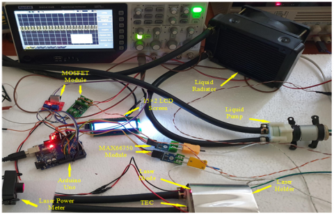
The proposed controlled LD cooling system was tested in a real environment, with the proposed system connected as shown in Figure 5 and the hardware components wired as shown in the system schematic in Figure 3.
Figure 3. Thermoelectric Cooler device
Figure 4. Proposed cooling system procedure
Figure 5. Experimental setup for the proposed controlled cooling system
Before the performance of the proposed LD cooling system could be evaluated, the PID controller's KP, KI, and KD parameters had to be determined using a simulation in MATLAB. A trial-and-error procedure was used to determine the values of the KP, KI, and KD parameters to ensure the optimal response and meet specific criteria, described below.
The criteria that needed to be achieved in the proposed cooling system are fastest rising time, shortest settling time, smallest overshoot, and minimum steady-state error. The temperature versus time curves for the different tests of the PID controller are shown in Figure 6, where each line corresponds to different values of the PID gain parameters. As shown in the curves in Figure 6, as KP increases, the settling time and steady-state error increase and the overshoot decreases. Furthermore, when KI increases, the settling time and steady-state error decrease but the overshoot increases; however, this overshooting can be overcome by increasing KD.
Figure 6. Step response for the proposed system based on different values of (KP, KI, and KD)
The changes in the system's characteristic parameters as a function of KP, KI, and KD are shown in Table 1. As shown, the characteristics’ parameters do not uniformly increase, decrease, or change; rather, the changes are erratic. Considering that the control characteristic settling time, steady-state error, and overshoot change as a function of KP, KI, and KD, by comparing curves obtained from multiple tries, the optimal value of the gain parameters (KP, KI, and KD) can be obtained. The gain parameter values that meet the criteria of the proposed cooling system are KP= 1,000, KI=40, and KD=5,000.
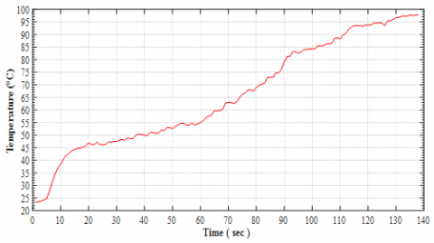
To analyse the performance of the proposed cooling system, the first step involves recording the temperature of the OCLARO HL63163DG LD without using the controlled cooling system. As shown in Figure 7, the temperature of LD rises to reach 97.75℃ after 138 seconds of operation. The second step is to measure the output optical power of the LD using a thermopile optical power meter to elucidate the effect of temperature on the LD. Rapidly increasing, high LD temperatures cause serious problems to the OCS, with the output optical power of the LD dropping from 82.4 mW when supplied by a 160 mA current at 23.5℃ to 49.7 mW at 97.75℃. Therefore, the LD needs to be cooled efficiently to overcome these problems.
Figure 7. Real-time temperature of LD recorded without using a cooling system
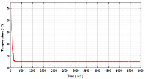
The proposed PID-based controlled LD cooling system was simulated using MATLAB. The LD temperature was set at 70°C at the start of the simulation of the proposed system, with the simulation showing that the LD was cooled from 70℃ to the setpoint temperature of 25℃ in 170 seconds and settled well at that temperature throughout 6,000 seconds of testing time, as shown in Figure 8. The stability of the LD temperature throughout this protracted testing time gives a clear indication of the effectiveness of the proposed system.
Figure 8. Simulation of the LD temperature when cooled by the proposed cooling system
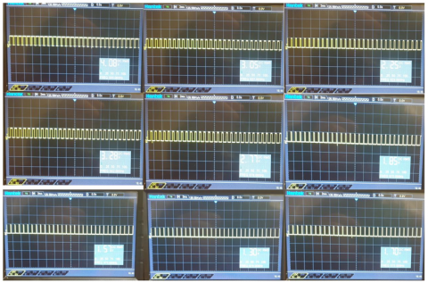
The real-time PWM signals that are output from the Arduino board to control the TEC module operation are shown in Figure 9.
Table 1. Changes in the system's characteristic parameters as a function of the (KP, KI, and KD)
|
PID gain parameter values |
Rising time (sec) |
Settling time (sec) |
Steady-state error (°C) |
Overshoot percentage (%) |
|
KP= 250, KI=10, KD=500 |
9.3 |
130 |
± 0.082 |
19.2 |
|
KP= 250, KI=20, KD=500 |
9.6 |
120 |
± 0.064 |
34.4 |
|
KP= 250, KI=40, KD=500 |
9.9 |
90 |
± 0.048 |
51.5 |
|
KP= 250, KI=40, KD=5,000 |
10.2 |
112 |
± 0.1 |
24.4 |
|
KP= 500, KI=10, KD=500 |
9.6 |
205 |
± 0.062 |
10.7 |
|
KP= 500, KI=20, KD=500 |
9.8 |
145 |
± 0.04 |
28.9 |
|
KP= 500, KI=40, KD=500 |
10.1 |
126 |
± 0.036 |
34.6 |
|
KP= 500, KI=40, KD=5,000 |
10.6 |
140 |
± 0.042 |
17.8 |
|
KP= 1,000, KI=10, KD=500 |
9.8 |
290 |
± 0.17 |
6.2 |
|
KP= 1,000, KI=20, KD=500 |
9.9 |
210 |
± 0.055 |
10.5 |
|
KP= 1,000, KI=40, KD=500 |
10.5 |
140 |
± 0.012 |
20.2 |
|
KP= 1,000, KI=40, KD=5,000 |
11.2 |
145 |
± 0.014 |
10.6 |
Figure 9. Samples of Output PWM signal to control TEC module operation
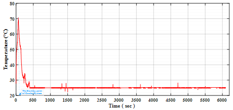
Figure 10. Real-time temperature of the LD when cooled by the proposed controlled cooling system
The real-time temperature of the LD when cooled to the proposed controlled cooling system was recorded using K-type thermocouple temperature sensors and the Arduino board, as shown in Figure 10. The temperature versus time curve in Figure 10 shows that the LD temperature increases rapidly when the cooling system is not in operation. With the onset of operation of the cooling system, the LD temperature decreases until reaching 25℃ (i.e. the setpoint temperature of the proposed cooling system). The time needed to reach 25℃ from 71℃ (LD temperature before running the proposed cooling system) is 176 sec. This time value is very close to the time obtained from the simulation of the proposed system was tested across 6,000 sec of operation, with the LD temperature showing good stability around the setpoint temperature.
The output optical power of the LD measured before running the proposed controlled cooling system was 57.4 mW when the supplied current to the LD was 160 mA and the LD case temperature was 71℃. After running the proposed controlled cooling system, the output optical power of the LD was 82 mW at the settling temperature (25℃) and a supplied current of 160 mA.
This study described a controlled cooling system for an optical communication semiconductor laser diode using a TEC module, an Arduino Uno microcontroller board, and a PID controlling algorithm. Firstly, the effects of operating the LD without a cooling system on temperature, performance, and LD output optical power were analysed. According to the thermal behaviour and characteristic curves of the LD in optical communication, a PID controlled cooling system based on a TEC was designed. The MATLAB-based simulation results for the proposed controlled cooling system proved its reliability. Subsequently, an Arduino Uno board with several modules was used to implement a real-time controlled cooling system. The PWM signals from the Arduino Uno board were used to control the TEC module and a liquid radiator cooler. The results of the real-time proposed controlled cooling system demonstrate its capability for cooling LDs and preserving LDs temperatures at a certain value related to the OCS design. The experimental results show that the proposed system successfully decreased LD temperature from 71℃ to 25℃. Furthermore, the controller also succeeded in keeping the temperature stable. These experiments show a fast, smooth system response with negligible overshooting, with 176 sec taken to settle the temperature at 25℃. These findings clearly show the successful design and robustness of the proposed system. Other classes of LD temperature controllers, such as those described in this paper, may be developed in the future using the approach provided in this study, including controllers that allow the desired temperature to be set using a user interface and temperature controllers for solid-state lasers.
|
A |
electrical current |
|
AI |
Artificial Intelligence |
|
°C |
degree Celsius |
|
FSO |
free-space optical |
|
KD |
PID derivative TERM |
|
KI |
PID integral term |
|
KP |
PID proportional term |
|
LD |
laser diode |
|
OCSs |
Optical communication systems |
|
PID |
proportional integral derivatives |
|
PVs |
control process variables |
|
SP |
set output point |
|
TEC |
thermoelectric cooler |
|
W |
power or radiant flux kg⋅m2⋅s-3 |
|
Greek symbols |
|
|
$\phi$ |
Diameter |
|
Subscripts |
|
|
D |
derivative |
|
I |
integral |
|
P |
proportional |
[1] Ali, S.H. (2019). Advantages and limits of free space optics. International Journal of Advanced Smart Sensor Network Systems, 9: 1-6. https://doi.org/10.5121/ijassn.2019.9301
[2] Ujager, F.S., Zaidi, S.M.H., Younis, U. (2010). A review of semiconductor lasers for optical communications. 7th International Symposium on High-Capacity Optical Networks and Enabling Technologies, Cairo, Egypt, pp. 107-111. https://doi.org/10.1109/HONET.2010.5715754
[3] Gupta, A., Anand, P., Khajuria, R., Bhagat, S., Jha, R.K. (2014). A survey of free space optical communication network channel over optical fiber cable communication. International Journal of Computer Applications, 105: 32-36. https://doi.org/10.5120/18416-9711
[4] Chun, H., Rajbhandari, S., Tsonev, D., Faulkner, G., Haas, H., O’Brien, D. (2015). Visible light communication using laser diode based remote phosphor technique. 2015 IEEE International Conference on Communication Workshop, ICCW 2015, pp. 1392-1397. https://doi.org/10.1109/ICCW.2015.7247373
[5] Sharma, D., Khan, S.A., Singh, S. (2015). Understanding the performance analysis of free space optical communication using red laser 650nm wavelength. International Journal of Engineering Research & Technology, 79(11): 1345-1353. https://doi.org/10.17577/IJERTV4IS040985
[6] Milonni, P.W., Eberly, J.H. (2010). Diode lasers and optical communications. Laser Physics, pp. 735-792. https://doi.org/10.1002/9780470409718.ch15
[7] Adnan, S.A., Alchalaby, A., Hassan, H.A. (2021). Future optimization algorithm to estimate attenuation in 532 nm laser beam of UWOC-channel: Improved neural network model. Mathematical Modelling of Engineering Problems, 8(3): 453-460. https://doi.org/10.18280/mmep.080316
[8] Garlinska, M., Pregowska, A., Gutowska, I., Osial, M., Szczepanski, J. (2021). Experimental study of the free space optics communication system operating in the 8–12 µm spectral range. Electronics, 10(8): 875. https://doi.org/10.3390/electronics10080875
[9] Yin, M., Krier, A., Krier, S., Jones, R., Carrington, P. (2006). Mid-infrared diode lasers for free-space optical communications. Advanced Free-Space Optical Communication Techniques/Applications II and Photonic Components/Architectures for Microwave Systems and Displays, 6399: 63990C. https://doi.org/10.1117/12.688238
[10] Asmari, A., Hodgkinson, J., Chehura, E., Staines, S.E., Tatam, R.P. (2017). All-electronic frequency stabilization of a DFB laser diode. Optics Express, 25(10): 11679-11691. https://doi.org/10.1364/OE.25.011679
[11] Adnan, S.A., Hassan, H.A., Alchalaby, A., Kadhim, A.C. (2021). Experimental study of underwater wireless optical communication from clean water to turbid harbor under various conditions. International Journal of Design & Nature and Ecodynamics, 16(2): 219-226. https://doi.org/10.18280/ijdne.160212
[12] Taleb, S.M., Fakhri, M.A., Adnan, S.A. (2020). Substrate and annealing temperatures effects on the structural results of LiNbO3 photonic films using PLD method. In AIP Conference Proceedings, 2213(1). https://doi.org/10.1063/5.0000197
[13] Samsuddin, N.I., Hasbullah, N.F., Ahmad, S. (2011). Fuzzy logic based temperature control of thermoelectric cooler (TEC) for single photon avalanche diode (SPAD) application. 2011 4th International Conference on Mechatronics: Integrated Engineering for Industrial and Societal Development, ICOM’11 - Conference Proceedings, pp. 17-19. https://doi.org/10.1109/ICOM.2011.5937146
[14] Jiang, W., Jiang, X. (2012). Design of an intelligent temperature control system based on the fuzzy self-tuning PID. Procedia Engineering, 43: 307-311. https://doi.org/10.1016/j.proeng.2012.08.053
[15] Mohammed Salim, O.N. (2017). New neuro-fuzzy system-based holey polymer fibers drawing process. AIP Advances, 7(10): 105301. https://doi.org/10.1063/1.4998270
[16] Sinulingga, D.F., Prasetyawati, F.M., Palebangan, F.M., Suhendi, A., Ajiwiguna, T.A., Handayani, I.P., Fathonah, I.W. (2017). PID temperature controlling of thermoelectric based cool box. In 2017 International Conference on Control, Electronics, Renewable Energy and Communications (ICCREC), pp. 236-240. https://doi.org/10.1109/ICCEREC.2017.8226671
[17] Oelschlegel, M., Bachnak, R. (2003). A project in PID temperature control and loop tuning. In 2003 Annual Conference, 13863-13873. http://dx.doi.org/10.18260/1-2--12258
[18] Huang, H., Fu, S., Zhang, P., Sun, L. (2016). Design of a small temperature control system based on TEC. In 2016 9th International Symposium on Computational Intelligence and Design (ISCID), pp. 193-196. https://doi.org/10.1109/ISCID.2016.1051
[19] Ali, A., Alaoui, C. (2012). FPGA-based control of thermoelectric coolers for laser diode temperature regulation. International Journal of Engineering Science and Technology, 4(4): 1628-1633.
[20] Chein, R., Huang, G. (2004). Thermoelectric cooler application in electronic cooling. Applied Thermal Engineering, 24: 2207-2217. https://doi.org/10.1016/j.applthermaleng.2004.03.001
[21] Zhang, J., Li, H., Ma, K., et al. (2018). Design of PID temperature control system based on STM32. In IOP Conference Series: Materials Science and Engineering, 322(7): 072020. https://doi.org/10.1088/1757-899X/322/7/072020
[22] Singh, Y.K., Kumar, J., Pandey, K.K., Rohit, K., Bhargav, A. (2016). Temperature control system and its control using PID controller. International Journal of Engineering Research and Technology, 4(2): 4-6.
[23] Mutlag, A.H., Salim, O.N.M., Mahdi, S.Q. (2021). Optimum PID controller for airplane wing tires based on gravitational search algorithm. Bulletin of Electrical Engineering and Informatics, 10: 1905-1913. https://doi.org/10.11591/eei.v10i4.2953
[24] Misses, M.A.O., lópez, J.C.G. (2020). Temperature control for Newton’s Law of Cooling using PID Controller. IEEE DataPort. https://dx.doi.org/10.21227/gg33-sm32
[25] Al-awad, N.A. (2020). Optimal controller design for reduced-order model of rotational mechanical system. Mathematical Modelling of Engineering Problems, 7(3): 395-402. https://doi.org/10.18280/mmep.070309
[26] Sailaja, V., Raju, K.N. (2019). PID controller tuning using Ziegler-Nichols method for temperature control of thermal cycler. International Journal of Advanced Research in Electrical, Electronics and Instrumentation Engineering, 8(4): 1289-1296.
[27] Jacob, N., Kaur, B. (2020). Combining LMS with PID control for H-bridge controlled thermal electric cooler (TEC). In Mobile Multimedia/Image Processing, Security, and Applications 2020, 1139905. https://doi.org/10.1117/12.2563298
[28] Lee, C., Chen, R. (2015). Optimal self-tuning PID controller based on low power consumption for a server fan cooling system. Sensors (Switzerland), 15: 11685-11700. https://doi.org/10.3390/s150511685
[29] Shubbar, M.M., Abdul-Rahaim, L.A., Hamad, A.A. (2021). Cloud-based automated power factor correction and power monitoring. Mathematical Modelling of Engineering Problems, 8(5): 757-762. https://doi.org/10.18280/mmep.080510
[30] Saha, T., Jewel, M.K.H., Mostakim, M.N., Bhuiyan, N. H., Ali, M.S., Rahman, M.K., Ghosh, H.K., Hossain, M.K. (2017). Construction and development of an automated greenhouse system using Arduino uno. International Journal of Information Engineering and Electronic Business, 9(3): 1-8. https://doi.org/10.5815/ijieeb.2017.03.01
[31] Erham, E., Surjanto, A., Rukmana, J. (2018). Design of a new PID controller based on Arduino Uno R3 with application to household refrigerator. In MATEC Web of Conferences, 154: 01044. https://doi.org/10.1051/matecconf/201815401044
[32] Najmie, M.S., Fadzly, M.K. (2019). Thermoelectric portable water cooler using Arduino Uno. In AIP Conference Proceedings, 2129(1): 020147. https://doi.org/10.1063/1.5118155
[33] Li, Y., Zhang, L. (2013) Design of digital K-type thermocouple temperature transmitter. Applied Mechanics and Materials, 433-435: 217-220. https://doi.org/10.4028/www.scientific.net/AMM.433-435.217