Ruslan Kudabayev | Ulanbator Suleimenov | Raimberdi Ristavletov | Irkin Kasimov | Medetbek Kambarov* | Nurlan Zhangabay | Khassen Abshenov
© 2022 IIETA. This article is published by IIETA and is licensed under the CC BY 4.0 license (http://creativecommons.org/licenses/by/4.0/).
OPEN ACCESS
An increasing demand for energy and climate change encouraged the search for new ways of using renewable energy sources, including in building structures. At present, improving energy efficiency in buildings by integrating thermal energy storage materials is an urgent task. This paper proposes a mathematical model for the thermal regime in a building with a TES building envelope. The enclosure model consists of gypsum board with 25% of phase change material (PCM). The PCM layers of different thickness reduce room temperature and heat load. The effectiveness evaluation of the proposed model involved calculating the thermal conductivity using the finite difference method. The results show that the incorporation of thermal energy storage materials can reduce temperature fluctuations in the room and maintain a comfortable temperature for a long time (up to 8 hours). With an increase in the thickness of the thermal energy storage layer, the cooling time of the exterior surface of the internal wall also increases.
energy-active envelope, phase change material, thermal energy storage, modeling thermal regime of a room
Intensive economic growth and enhancement of living standards in many developed and developing countries around the world have led to an increased consumption of non-renewable energy resources, facilitating environmental pollution and acceleration of climate change. High fossil fuel consumption may lead to a rapid depletion of fossil energy sources in the near future. This problem also applies to the buildings construction sector, in which energy conservation and creation of energy-efficient buildings are a priority. Building maintenance accounts for around 30% of the final energy consumed in the world [1]. For the European Union, this figure is about 40% [2], where approximately 80% of the energy is utilized for space conditioning (heating and cooling) and ventilation purposes [3]. The recent issues are thus associated with energy efficiency during buildings construction and maintenance processes. In Europe, energy-efficient buildings must meet a number of requirements, such as building orientation and shape, envelope system, passive heating and cooling mechanisms, energy consumption below 60 W/m2 per year, and more [4]. For energy efficiency, various renewable energy systems have been developed, such as thermal energy storage (TES) systems and photovoltaic (PV) panels [5].
The whole range of design considerations for energy-efficient building construction stems from many years of experience and research. There is also a need for more studies on this matter given the growing threat of environmental and energy crises, as well as a rising demand for efficient use of material-technical resources. Taken together, the world experience in energy-saving buildings [6], research on the heat-shielding properties of the building envelopes [7], calculation-based experiments [8] and regulatory requirements [9-12] show that in an energy-efficient building design, the following specifications and insights should be taken into account:
In this way, energy saving can be achieved through optimization of building envelope and architectural design, the use of alternative types of energy, and enhancement of engineering systems.
Among the promising areas of energy conservation is the use of alternative sources of energy, such as solar radiation [13-15]. The energy-efficient building designs largely focus on ways to store solar radiation [16]. It appears that thermal energy consumption can be regulated efficiently by optimizing the exterior of a building [17]. The simplest and most indicative system for passive solar storage is a Trombe wall [18], designed to absorb solar radiation and convert it into thermal energy (heat) as it passes along the air channels, which is then transferred into the room via openings in the wall (vents). The Trombe wall consists if a double-layer translucent panel and a masonry wall placed at distance from the translucent panel to create an air space, usually made of bricks, with high thermal inertia.
The recently popular house designs involve the use of passive solar energy heating solutions, which combine transparent insulation materials and materials with high capacity to store heat [19]. The transparent insulation layer transmits radiation to the absorber and prevents the transfer of radiative, conductive, and convective heat in the opposite direction. The thermal energy storage layer, in this case, can be either gapless or with ventilation ducts and air spaces [20]. A gapless energy storage material transfers heat to the inner surface of the envelope, while the energy storage material with ventilation ducts and air spaces helps to heat up the ventilation air that comes from inside the house.
Theoretical and experimental studies [21, 22] show that with a well thought-through envelope design, the amount of solar gain can compensate a substantial portion of the heat loss of a building. The advantage of this constructive solution is that when the heat is emitted from the surface of the walls, a more favorable microclimate is created than with the convective heat from heating devices.
Latent heat TES materials have been recently rising in popularity because of their high energy density storage and the constant phase-transition temperature [23]. When using TES systems in building construction, it is important to determine the proper their thermophysical properties. Therefore, it is not possible to create a TES system design and model without verified data inputs [24].
Among the most environmentally friendly organic materials, paraffins are the more suitable option for thermal energy storage applications in residential buildings. The melting point of paraffins is directly related to the number of carbon atoms within the material structure, therefore they are suitable for storing different types of thermal energy, including solar energy [25], but they also have disadvantages, such as high flammability. At the same time, due to their non-corrosive properties, paraffins can be encapsulated into certain metallic and other materials [26], which allows overcoming the risk of leakage. The use of alternative solar energy in buildings has its own distinctive features associated with the number of storeys, layout complexity, and heat supply organization [27].
Some authors propose an energy-saving envelope design with an energy-active panel [28-30], which enhances the energy performance and heat storage capacity of the enclosure. The TES panel contains phase change particles that intensify the exchange of heat between the air channels in the envelope and the heat storage material inside the panel. Researchers report that the inclusion of 5% microencapsulated phase change materials (PCMs) into a concrete mix can save up to 12% of thermal energy that can be used to heat the room [31]. In addition, the incorporation of PCMs into the building structures can reduce the fluctuation of interior temperature against the background of change in the outdoor temperature. For example, the concrete walls incorporated around 30% commercial paraffin reduce the daytime temperature by 10℃ compared to walls without such an enhancement [32]. PCMs can also be incorporated into light timber wallboards, windows and other structures [33] to maintain a comfortable temperature in the room. However, before incorporating PCMs, it is necessary to accurately determine their thermal properties and properties of the building structures. A high-quality accurate model may help solve this problem and explore the advantages and disadvantages of using TES materials in the construction process, as well as calculate the best conditions to reduce temperature fluctuations in the room. This paper aims to develop a mathematical model for the thermal regime in a building with a TES building envelope.
2.1 Input data
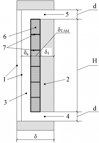
It is known that paraffin-based TES materials are compatible with mineral, silicate and polymeric materials. They can be used in buildings in different ways: (1) as part of the enclosure to improve building envelope thermal performance; (2) as additives added to dry building mixtures, paints, varnishes, and building materials (such as bricks, foam blocks or stones, panels, etc.); and (3) as a fill for voids in hollow or sandwich structures. For example, consider an energy-saving enclosure design (Figure 1) that has an energy-active TES panel with phase change particles that intensify heat exchange between air channels and the heat storage material in the panel.
Figure 1. An energy-efficient building envelope design
The proposed design of an energy-efficient building envelope consists of a glazing system 1; a load-bearing layer 2, shown in light gray; air cavities 3, 4, and 5; TES layer 6, shown in dark gray; and high thermal conductivity particles 7.
The proposed enclosure design is paraffin-based. The paraffin has the following characteristics: melting point, Tf=25°C; liquid-phase density, ρl=780 kg/m3; solid-phase density, ρt=900 kg/m3; liquid phase heat capacity, comp=3.72 kJ/(kg·℃); solid phase heat capacity, ctw=2.91 kJ/(kg·℃); liquid phase thermal conductivity, λl=0.146 W/(m·K); and solid phase thermal conductivity, λw=0.3 W/(m·K). In the phase transition zone, thermophysical characteristics are calculated with regard to the liquid-to-solid ratio.
The wall has three layers. The first or inner layer is TES material. The second or intermediate layer is an insulation with thermal conductivity of 0.06 W/(m·K) and thickness 250 mm. Finally, the third or outer layer is 510 mm thick brick cladding. The room has a dimension of 3 m (width) × 5 m (length) × 2.5 m (height) and a volume of 37.5 m3. Wall area minus window area (1 m2) is 6.5 m2. The TES layer thickness was taken as 30, 60 and 100 mm.
The main objective of this study is to evaluate the effect of TES layers on the thermal performance of a building envelope. The focus is laid on a relationship between TES layer thickness, building envelope surface temperature, and room temperature.
2.2 Mathematical model and solution
Heat supply systems in buildings rely on heat sources that operate on an occasional basis, which leads to temperature fluctuations in the room (4-7℃ depending on the thermal inertia of a building, as well as heating system settings). The peak energy consumption is observed during daytime hours when the room temperature is within the comfortable range of 20-23℃. At night, the temperature of air in the room is usually lowered to a 10℃ standard. In these conditions, a diverse range of TES solutions can be used, which allow smoothing out temperature unevenness throughout the day while maximizing energy savings.
Materials for phase change thermal energy storage can serve as an effective heat storage solution. Such materials can absorb and store a relatively large amount of thermal energy (heat) in the temperature range of 18-23℃. Therefore, they can be used in building envelopes, but the question is how effective they can be. To answer this question, the present paper developed a mathematical model of the thermal regime of a room in the presence of TES layers in the building envelope.
The model is based on the problem of heat-transfer during solid-liquid phase transition (Stefan problem) [11, 12]. The heat balance equation is given as:
$\mathcal{C} a \rho a V_{r} \frac{\partial \mathrm{Text}}{\partial \tau}=\sum_{i}^{n} k_{w}\left(T_{i n t}-T_{e x t}\right) F_{w}$
$+\sum_{i}^{m}\left[\alpha_{\text {out }}\left(T_{e x t}-T_{F_{i}}\right)+\alpha_{i n}\left(T_{F_{i}}-T_{R}\right)\right] F_{i}$ (1)
where, Ca is the heat capacity of air in the room; ρa is the density of air in the room; Vr represents room volume; Fw and Fe are window area and envelope area, respectively; Text and Tint are exterior temperature and interior temperature, respectively; $\tau_{F_{i}}$ represents the inner wall surface temperature; TR is the radiative room temperature; αout is the heat transfer coefficient of the outer wall surface; αin is the heat transfer coefficient of the inner wall surface; αrad is the equivalent radiative heat transfer coefficient; and kw is the heat transfer coefficient of a window.
The thermal conductivity equation is given as:
$c_{i} \rho_{i} \frac{\partial T_{i}}{\partial \tau}=\lambda_{i} \quad \frac{\partial_{2} T_{i}}{\partial x^{2}}$ (2)
with boundary conditions for the outer wall expressed as:
$-\left.\lambda_{i} \frac{\partial T_{i}}{\partial x_{i}}\right|_{x=\delta}=\alpha_{H}\left(T_{i}-T_{r}\right)$
$-\left.\lambda_{i} \frac{\partial T_{i}}{\partial x_{i}}\right|_{x=0}=\alpha_{\text {out }}\left(T_{\text {ext}}-T_{\text {int}}\right)+\alpha_{\text {in }}\left(T_{i}-T_{R}\right)$ (3)
For inner and intermediate layers of the envelope, the following boundary conditions can be applied:
$\begin{aligned}-\left.\lambda_{i} \frac{\partial T_{i}}{\partial x_{i}}\right|_{x=0}=& \alpha_{\text {out }}\left(T_{\text {ext}}-T_{\text {int }}\right)+\alpha_{\text {in }}\left(T_{i}-T_{R}\right), \\ &-\left.\lambda_{i} \frac{\partial T_{i}}{\partial x_{i}}\right|_{x=\delta / 2}=0 \end{aligned}$ (4)
A one-dimensional, two-phase model of the TES layer can be expressed as follows:
$(c \rho) l \frac{\partial T T}{\partial \tau}=\frac{\partial}{\partial x}\left(\lambda_{s} \frac{\partial T}{\partial x}\right), \xi(\tau)<\mathrm{x}<\delta_{T E S}, \tau$
$(c \rho) l \frac{\partial T}{\partial \tau}=\frac{\partial}{\partial x}\left(\lambda, \frac{\partial T}{\partial x}\right), 0<\mathrm{x}<\xi(\tau), \tau>0$
$\left.\lambda_{s} \frac{\partial T}{\partial x}\right|_{\xi-0}-\left.\lambda_{l} \frac{\partial T}{\partial x}\right|_{\xi+0}=\rho_{\mathrm{ext}} \operatorname{int} \frac{d \xi}{d \tau}, \mathrm{x}=\xi(\tau)$
$\left.T\right|_{\xi-0}-\left.T\right|_{\xi+0}=T_{\mathrm{int}}$ (5)
where, λs and λl are coefficients of thermal conductivity; (сρ)s and (сρ)l represent specific heat capacity of TES material in solid and liquid phases, respectively; Tp represents phase-transition temperature, qp is the amount of phase-transition heat; δ is the envelope thickness; and δTES is the thickness of the inner wall (TES layer).
Eq. (1) is an equation of parabolic type with discontinuous coefficients, which has first-order discontinuities. The best method to solve thermal conductivity equation via software is the finite difference method.
Let Δt be the spacing of the grid points in the t direction and Δh be the spacing of the grid points in the h direction. The approximate value of the temperature derivative with respect to time ($\frac{\partial T}{\partial t}$) at the node $y_{i}, t_{j}$ can thus be replaced with this implicit difference scheme:
$\frac{T_{i, j}-T_{i, j-1}}{\Delta t}=\left(f T_{i, j}\right)$
Assume the domain of variables (x, t) be a rectangular network, i.e.,
$R=\left(0 \leq x \leq \delta ; 0 \leq t \leq t_{\text {end }}\right)$
In this case, the section (0, δ) can be divided into M parts to introduce arbitrary points $x_{0}=0<x_{1}<x_{2}<\cdots<x_{M}=\delta$, whereas the section (0, $t_{\text {end }}$) can be segmented into N parts with arbitrary points $t_{0}=0<t_{1}<t_{2}<\cdots<t_{N}=t_{\text {end }}$. Let the distance between points xi and xi-1 be Δhi, and the distance between points tj and xj-1 be Δtj, where i=1,2,…, M and j=1,2,…, N. The set of nodes $x_{i}=i \Delta h_{i}$ and $t_{j}=j \Delta t_{j}$ will be called a grid in the rectangle R.
To convert Eq. (1) into a finite-difference model, it was integrated with a rectangular network $\left(X_{i-0.5} \leq x \leq x_{i+0.5} ; t_{j-1} \leq t \leq t_{j}\right)$, where xi-0,5 and xi+0,5 are expressed from the following equation.
$\int_{x_{i-0.5}}^{x_{i+0.5}} \int_{t_{j-1}}^{T_{j}}\left[c(\mathrm{x}) \rho(\mathrm{x}) \mathrm{V}_{n} \frac{\partial T_{e}}{\partial t}\right] d x d t$
$\mathrm{x}=\int_{x_{i-0.5}}^{x_{i+0.5}} \int_{t_{i-1}}^{t_{i}}\left[\sum_{i}^{n} k_{w}\left(T_{e x t}-T_{i n t}\right) F_{i n t}\right] d x d t+$
$\left.\quad+\int_{x_{i-0.5}}^{x_{i+0.5}} \int_{t_{j-1}}^{t_{j}}\left[\sum_{i}^{m}\left[\alpha_{o u t}\left(T_{i n t}-T_{F i}\right)\right] \alpha_{i n}\left(T_{F i}-T_{R}\right)\right] F_{i}\right]\underline{dxdt}$ (6)
Consider each integral on the left and right sides of Eq. (6) separately. When calculating the integral on the left-hand side of Eq. (6), assume that T(х)=const=T(хi) and lies in the range $x_{i-0.5} \leq x \leq x_{i+0.5}$ . In this case, we get:
$\begin{aligned}
&\int_{x i-0.5}^{x i+0.5} \int_{t_{j}-1}^{t_{j}}\left[c(\mathrm{x}) \rho(\mathrm{x}) \mathrm{V}_{n} \frac{\partial T}{\partial t}\right] d x d t \\
&=\int_{x i-0.5}^{x i+0.5} c(\mathrm{x}) \rho(\mathrm{x})\left[\begin{array}{c}
T\left(\mathrm{x}, t_{j}\right) \\
-T\left(\mathrm{x}, t_{j-1}\right)
\end{array}\right] d x= \\
&=\frac{h\left(\begin{array}{l}
c\left(\mathrm{x}_{i}\right) \rho\left(\mathrm{x}_{i}\right) \\
+c\left(\mathrm{x}_{i+1}\right) \rho\left(\mathrm{x}_{i+1}\right)
\end{array}\right)\left(T_{i, j}-T_{i, j-1}\right)}{2}
\end{aligned}$ (7)
The first integral on the right-hand side of Eq. (6) can be replaced by:
$\begin{aligned}
&\left.\int_{x i-0.5}^{x i+0.5} \int_{t j-1}^{t_{j}}\left[\sum_{i}^{n} k_{o \kappa}\left(T_{H}-T_{B}\right) F\right)\right] d y d t \\
&=\left[\sum_{i}^{n} k_{o \kappa}\left(T_{H}-T_{B}\right) F_{o \kappa}\right] \\
&\int_{x-0.51}^{x i+0.5}\left(t_{j}-t_{j-1}\right) d x= \\
&=\frac{1}{2}\left[\sum_{i}^{n} k_{o \kappa}\left(T_{H}-T_{B}\right) F_{o \kappa}\right] \\
&\left(t_{j}-t_{j-1}\right)\left(x_{i+1-}-\mathbf{x}_{i-1}\right)
\end{aligned}$ (8)
Similarly, the second integral can be expressed as:
$\begin{aligned}
&\int_{x_{i-0.5}}^{x_{i+0.5}} \int_{t_{j-1}}^{t_{j}}\left[\sum_{i}^{m}\left[\begin{array}{l}
\alpha_{\text {out }}\left(T_{B}-T_{F_{i}}\right) \\
+\alpha_{i n}\left(T_{F i}-T_{R}\right)
\end{array}\right] F_{i}\right] d x d t= \\
&=\frac{1}{2}\left[\sum_{i}^{m}\left[\begin{array}{l}
\left.\alpha_{\text {out }}\left(T_{B}-T_{F i}\right)\right] \\
+\alpha_{\text {in }}\left(T_{F_{i}}-T_{R}\right)
\end{array}\right] F_{i}\right] \\
&\left(t_{j}-t_{j-1}\right)\left(x_{i+1}-\mathbf{x}_{i-1}\right)
\end{aligned}$ (9)
After integration, Eq. (1) is replaced by this finite-difference equation:
$\frac{h V_{n}\left(\begin{array}{l}c\left(\mathrm{x}_{i}\right) \rho\left(\mathrm{x}_{i}\right) \\ +c\left(\mathrm{x}_{i+1}\right) \rho\left(\mathrm{x}_{i+1}\right)\end{array}\right)}{2}\left(T_{i j}-T_{i, j-1}\right)$
$=\frac{1}{2}\left[\sum_{i}^{n} k_{w}\left(T_{e x t}-T_{\text {int }}\right) F_{w}\right]\left(t_{j}-t_{j-1}\right)$
$=\frac{1}{2}\left[\sum_{i}^{m}\left[\begin{array}{c}\alpha_{\text {out }}\left(T_{B}-T_{F i}\right) \\ +\alpha_{\text {in }}\left(T_{F i}-T_{R}\right)\end{array}\right] F_{i}\right]$
$\left(t_{j}-t_{j-1}\right)\left(\mathrm{x}_{i+1}-x_{i+1}\right)$
$i=1,2, \ldots,=M-1 ; \quad j=1,2, \ldots, N$ (10)
The boundary conditions (3-4) for this finite-difference equation can be expressed as follows:
$-\lambda_{M} \frac{T_{M, j}-T_{M-1, j}}{h}$
$=\alpha_{s}\left(T_{M, j}-T_{s}\right)$
$-\lambda \frac{T_{1, j}-T_{0, j}}{h}$
$=\alpha_{o u t}\left(T_{B}-T_{0, j}\right)+\alpha_{i n}\left(T_{0, j}-T_{R}\right)$; (11)
To solve the system of finite-difference Eqns. (10-12), the sweep method was used. A solution is be in the following form:
$T_{\mathrm{i}, j}=\tilde{\alpha}_{i+1} T_{\mathrm{i}+1, j}-\beta, \quad i=0,1,2, \ldots, \mathrm{M}-1 \$$
where, $\tilde{\alpha}_{i+1}$ and $\tilde{\beta}_{i+1}$ are sweep coefficient.
A formula to calculate TM,j is obtained from a boundary condition (11), as shown below:
$T_{M, j}=-\frac{\lambda_{M} T_{M-1, j}+\alpha_{\mathrm{s}} T_{H}}{\lambda_{M}+\alpha_{s} h}$
$=\frac{0.25 T_{M-1, j}+23(-20)}{0.25+23 \cdot h}$ (12)
Substituting the primary inputs (see subsection 2.1), we get:
$T_{i, j}=\frac{\sum_{i}^{m}\left[\begin{array}{l}2(20-6) \\ +8,7(16-20)\end{array}\right] 6,5 \cdot \Delta t \cdot 2 h}{h \cdot 37,5 \cdot 1005 \cdot 1,205}-$
$-T_{i, j-1}=\frac{\sum_{i}^{m}\left[\begin{array}{l}2(20-6) \\ +8,7(16-20)\end{array}\right] 6,52 \cdot \Delta t \cdot 2}{37,5 \cdot 1005 \cdot 1,205}$
$-T_{i, j-1}$
$i=1,2, \ldots, M-1 ; \quad j=1,2, \ldots, N$ (13)
Dividing a grid into 100 smaller sections along the x and t axes, one can obtain determine temperature values at the nodes. If the initial air temperature is 20℃, then the subsequent values will be calculated according to Eq. (13).
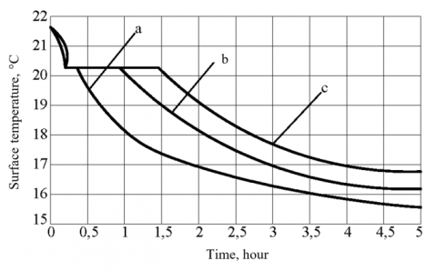
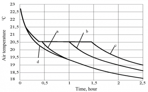
The calculation results are presented as graphs illustrating changes over time in the temperature of the exterior surface of the wall and air temperature as the room cools down depending on the thickness of the TES material inside the wall (Figures 2 and 3).
Figure 2. Temperature behavior of the exterior surface of the inner wall having the following thickness: (а) 30 mm, (b) 60 mm, and (с) 100 mm
Figure 3. Temperature behavior of air in a room: (a) 30 mm thick TES layer; (b) 60 mm thick TES layer; (с) 100 mm thick TES layer; (d) without TES
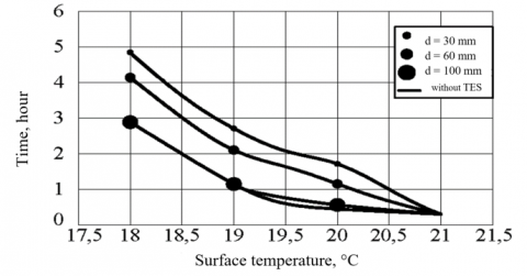
Figure 4. Cooling dynamics of TES layer depending on thickness
It appears that in the absence of phase transition, the cooling process of air in the room takes place as with the regular, non-stationary heat transfer according to the exponential law.
In the phase transition, the temperature of the interior surface of the TES material falls to the temperature of crystallization Tp and a material goes from a liquid to a solid phase, releasing phase transition heat qp. The temperature of the whole TES layer becomes equal to that of phase transition Tp. As the TES material crystallizes, the phase transition boundary shifts to the inner surface of the wall. Crystallization ends when the phase transition boundary reaches the inner surface of the TES material. The graphs depict this moment by means of a horizontal line.
According to calculations, the time of phase transition is not proportional to the thickness of the TES material. Therefore, the retention time of comfortable room temperature must be non-proportional to the thickness of the TES material as well.
Figure 4 shows a dependence between temperature behavior of TES layer and its thicknesses as the wall cools down. It appears that after crystallization is completed, the cooling process stops and the regular heat exchange takes place. Furthermore, it seems that a thicker TES layer tends to cool down faster. For example, while with a 30 mm thick layer of TES material inside the wall, the exterior surface temperature of the wall falls to 18℃ in 5 hours, with a 100 mm thick layer of such material, the cooling takes just 3 hours. There is no obvious difference in room temperature between TES layers of different thickness before 0.5 h. Hence, TES material is effective in maintaining a comfortable temperature (20-23℃) in a room within a short period.
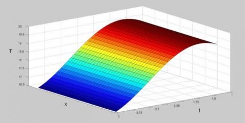
Figure 5. Cooling dynamics of air in a room: Т – temperature, t – time, х -space coordinate
Figure 5 depicts a time dependence of room temperature and inner wall thickness. Note that a comfortable room temperature retention time can be adjusted by changing the thickness of the TES layer, an important factor for room temperature stability. The ability to store thermal energy is crucial for the efficient use of solar energy in buildings. The results obtained in this study are in good agreement with other studies. It is reported that the melting-point temperature of commercial paraffins can be tailored by mixing paraffins that show different phase transitions [34]. It was found that a large heat transfer area of the wall supports a large heat transfer between the wall and the room space [35]. Therefore, the incorporation of encapsulation PCMs into the wallboards is a suitable and cheap way to improve energy efficiency of a building. For passive solar applications, some authors suggest using drywall panels impregnated with paraffin [36, 37]. The incorporation of PCMs into drywall panels can be done at the initial stage of manufacturing and after the panel is made. Studies on the thermal dynamics of paraffin impregnated drywall panels [25, 38, 39] show that this type of panels are suitable for maintaining a comfortable room temperature, which aligns with the present work.
Experimental and numerical simulations with internal walls covered with plasterboard containing 25% PCMs show that integrating PCMs can reduce the maximum room temperature by about 4℃ during daytime house, as well as heat load by 2-3℃ at night [40]. A finite difference approach was implemented to assess thermal energy storage in drywall panels treated with PCMs [41] and the results revealed that the thermal mass of PCMs can be used to reduce the peak-power demand and down-size the cooling/heating systems. These findings align with the results of this work. In addition, the developed model can be utilized to decide on the optimal surface area and thickness of the TES component.
The present study investigated the thermal energy-saving effect of PCM-enhanced TES panels of varying thickness using a mathematical model. The integration of TES materials into wall structures allows reducing temperature fluctuations in the room and maintaining a comfortable temperature for a long time (up to 8 hours). A comfortable room temperature retention time can be regulated by changing the thickness of the TES layer. For instance, thicker TES panel allows retaining the heat longer. According to the results of modeling, the thermal mass of PCMs could be used to reduce the peak-energy demand and thus downsize the heating/cooling system.
|
PCMs |
phase change materials |
|
TES |
thermal energy storage |
[1] Gielen, D., Boshell, F., Saygin, D., Bazilian, M. D., Wagner, N., Gorini, R. (2019). The role of renewable energy in the global energy transformation. Energy Strategy Reviews, 24: 38-50. https://doi.org/10.1016/j.esr.2019.01.006
[2] Zavrl, E., Stritih, U. (2019). Improved thermal energy storage for nearly zero energy buildings with PCM integration. Solar Energy, 190: 420-426. https://doi.org/10.1016/j.solener.2019.08.041
[3] Shandilya, A., Hauer, M., Streicher, W. (2020). Optimization of thermal behavior and energy efficiency of a residential house using energy retrofitting in different climates. Civil Engineering and Architecture, 8(3): 335-349. https://doi.org/10.13189/cea.2020.080318
[4] Zhongming, Z., Linong, L., Wangqiang, Z., Wei, L. (2020). Energy Efficiency 2020. IEA. https://www.iea.org/reports/energy-efficiency-2020. accessed on June 12, 2021.
[5] Lizana, J., Friedrich, D., Renaldi, R., Chacartegui, R. (2018). Energy flexible building through smart demand-side management and latent heat storage. Applied Energy, 230: 471-485. https://doi.org/10.1016/j.apenergy.2018.08.065
[6] Michalak, P. (2021). Selected aspects of indoor climate in a passive office building with a thermally activated building system: A case study from Poland. Energies, 14(4): 860. https://doi.org/10.3390/en14040860
[7] Usta, P., Zengin, B. (2021). The energy impact of building materials in residential buildings in Turkey. Materials, 14(11): 2793. https://doi.org/10.3390/ma14112793
[8] Ferrante, A., Mochi, G., Predari, G., Badini, L., Fotopoulou, A., Gulli, R., Semprini, G. (2018). A European project for safer and energy efficient buildings: pro-get-one (proactive synergy of integrated efficient technologies on buildings’ envelopes). Sustainability, 10(3): 812. https://doi.org/10.3390/su10030812
[9] Salis, L.C.R., Abadie, M., Wargocki, P., Rode, C. (2017). Towards the definition of indicators for assessment of indoor air quality and energy performance in low-energy residential buildings. Energy and Buildings, 152: 492-502. https://doi.org/10.1016/j.enbuild.2017.07.054
[10] Bao, X., Tian, Y., Yuan, L., Cui, H., Tang, W., Fung, W.H., Qi, H. (2019). Development of high performance PCM cement composites for passive solar buildings. Energy and Buildings, 194: 33-45. https://doi.org/10.1016/j.enbuild.2019.04.011
[11] Jain, A., Parhizi, M. (2021). Conditionally exact closed-form solution for moving boundary problems in heat and mass transfer in the presence of advection. International Journal of Heat and Mass Transfer, 180: 121802. https://doi.org/10.1016/j.ijheatmasstransfer.2021.121802
[12] Wang, H., Lu, W., Wu, Z., Zhang, G. (2020). Parametric analysis of applying PCM wallboards for energy saving in high-rise lightweight buildings in Shanghai. Renewable Energy, 145: 52-64. https://doi.org/10.1016/j.renene.2019.05.124
[13] Duraković, B., Mešetović, S. (2019). Thermal performances of glazed energy storage systems with various storage materials: An experimental study. Sustainable Cities and Society, 45: 422-430. https://doi.org/10.1016/j.scs.2018.12.003
[14] Krese, G., Butala, V., Stritih, U. (2018). Thermochemical seasonal solar energy storage for heating and cooling of buildings. Energy and Buildings, 164: 239-253. https://doi.org/10.1016/j.enbuild.2017.12.057
[15] Shukla, A., Kant, K., Sharma, A. (2017). Solar still with latent heat energy storage: A review. Innovative Food Science and Emerging Technologies, 41: 34-46. https://doi.org/10.1016/j.ifset.2017.01.004
[16] Lizana, J., Chacartegui, R., Barrios-Padura, A., Valverde, J.M. (2017). Advances in thermal energy storage materials and their applications towards zero energy buildings: A critical review. Applied Energy, 203: 219-239. https://doi.org/10.1016/j.apenergy.2017.06.008
[17] Wang, Y., Yang, X., Xiong, T., Li, W., Shah, K.W. (2017). Performance evaluation approach for solar heat storage systems using phase change material. Energy and Buildings, 155: 115-127. https://doi.org/10.1016/j.enbuild.2017.09.015
[18] Wang, F., Yang, W.J., Sun, W.F. (2020). Heat transfer and energy consumption of passive house in a severely cold area: Simulation analyses. Energies, 13(3): 626. https://doi.org/10.3390/en13030626
[19] Pintaldi, S., Sethuvenkatraman, S., White, S., Rosengarten, G. (2017). Energetic evaluation of thermal energy storage options for high efficiency solar cooling systems. Applied Energy, 188: 160-177. https://doi.org/10.1016/j.rser.2014.08.062
[20] Ndiaye, K., Ginestet, S., Cyr, M. (2018). Thermal energy storage based on cementitious materials: A review. AIMS Energy, 6: 97-120. https://doi.org/10.3934/energy.2018.1.97
[21] Horn, R., Burr, M., Fröhlich, D., Gschwander, S., Held, M., Lindner, J.P., Munz, G., Nienbirg, B., Schossig, P. (2018). Life cycle assessment of innovative materials for thermal energy storage in buildings. Procedia CIRP, 69: 206-211. https://doi.org/10.1016/j.procir.2017.11.095
[22] Frazzica, A., Freni, A. (2017). Adsorbent working pairs for solar thermal energy storage in buildings. Renewable Energy, 110: 87-94. https://doi.org/10.1016/j.renene.2016.09.047
[23] Koukou, M.K., Vrachopoulos, M.G., Tachos, N.S., Dogkas, G., Lymperis, K., Stathopoulos, V. (2018). Experimental and computational investigation of a latent heat energy storage system with a staggered heat exchanger for various phase change materials. Thermal Science and Engineering Progress, 7: 87-98. https://doi.org/10.1016/j.tsep.2018.05.004
[24] Jeon, J., Park, J.H., Wi, S., Yang, S., Ok, Y.S., Kim, S. (2019). Latent heat storage biocomposites of phase change material-biochar as feasible eco-friendly building materials. Environmental Research, 172: 637-648. https://doi.org/10.1016/j.envres.2019.01.058
[25] Alva, G., Liu, L., Huang, X., Fang, G. (2017). Thermal energy storage materials and systems for solar energy applications. Renewable and Sustainable Energy Reviews, 68: 693-706. https://doi.org/10.1016/j.rser.2016.10.021
[26] Borodin, K., Zhangabay, N.Z. (2019). Mechanical characteristics, as well as physical-and-chemical properties of the slag-filled concretes, and investigation of the predictive power of the metaheuristic approach. Curved and Layered Structures, 6: 236-244. https://doi.org/10.1515/cls-2019-0020
[27] Qiu, F., Song, S., Li, D., Liu, Y., Wang, Y., Dong, L. (2020). Experimental investigation on improvement of latent heat and thermal conductivity of shape-stable phase-change materials using modified fly ash. Journal of Cleaner Production, 246: 118952. https://doi.org/10.1016/j.jclepro.2019.118952
[28] Shchukina, T.V., Sheps, R.F., Burak, E.E. (2018). Energy-saving regimes examination during new generation building structures insolation. In: IOP Conference Series: Materials Science and Engineering. IOP Publishing, 463(2): 022072. https://doi.org/10.1088/1757-899X/463/2/022072
[29] Gan, W., Cao, Y., Jiang, W., Li, L., Li, X. (2019). Energy-saving design of building envelope based on multiparameter optimization. Mathematical Problems in Engineering, 2019: 521869. https://doi.org/10.1155/2019/5261869
[30] Das, D., Bordoloi, U., Muigai, H.H., Kalita, P. (2020). A novel form stable PCM based bio composite material for solar thermal energy storage applications. Journal of Energy Storage, 30: 101403. https://doi.org/10.1016/j.est.2020.101403
[31] Ikutegbe, C.A., Farid, M.M. (2020). Application of phase change material foam composites in the built environment: A critical review. Renewable & Sustainable Energy Reviews, 131: 110008. https://doi.org/10.1016/j.rser.2020.110008
[32] Duissenbekov, B., Tokmuratov, A., Zhangabay, N., Yerimbetov, B., Aldiyarov, Z. (2020). Finite-difference equations of quasistatic motion of the shallow concrete shells in nonlinear setting. Curved and Layered Structures, 7: 48-55. https://doi.org/10.1515/cls-2020-0005
[33] Yao, C., Kong, X., Li, Y., Du, Y., Qi, C. (2018). Numerical and experimental research of cold storage for a novel expanded perlite-based shape-stabilized phase change material wallboard used in building. Energy Conversion and Management, 155: 20-31. https://doi.org/10.1016/j.enconman.2017.10.052
[34] Ren, M., Wen, X., Gao, X., Liu, Y. (2021). Thermal and mechanical properties of ultra-high performance concrete incorporated with microencapsulated phase change material. Construction and Building Materials, 273: 121714. https://doi.org/10.1016/j.conbuildmat.2020.121714
[35] Singh, S.P., Bhat, V. (2018). Performance evaluation of dual phase change material gypsum board for the reduction of temperature swings in a building prototype in composite climate. Energy and Buildings, 159: 191-200. https://doi.org/10.1016/j.enbuild.2017.10.097
[36] Ali, N., Sebzali, M., Bourisli, H., Safar, A., Ebrahem, Z. A. (2020). Nanocoating: An energy efficient solution towards reducing buildings electrical consumption in the state of Kuwait. In: 2020 Advances in Science and Engineering Technology International Conferences (ASET), pp. 1-4. https://doi.org/10.1109/ASET48392.2020.9118309
[37] Elias, C.N., Stathopoulos, V.N. (2019). A comprehensive review of recent advances in materials aspects of phase change materials in thermal energy storage. Energy Procedia, 161: 385-394. https://doi.org/10.1016/j.egypro.2019.02.101
[38] Du, K., Calautit, J., Wang, Z., Wu, Y., Liu, H. (2018). A review of the applications of phase change materials in cooling, heating and power generation in different temperature ranges. Applied Energy, 220: 242-273. https://doi.org/10.1016/j.apenergy.2018.03.005
[39] Martin, M., Villalba, A., Fernández, A.I., Barreneche, C. (2019). Development of new nano-enhanced phase change materials (NEPCM) to improve energy efficiency in buildings: Lab-scale characterization. Energy and Buildings, 192: 75-83. https://doi.org/10.1016/j.enbuild.2019.03.029
[40] Buonomo, B., Capasso, L., Diana, A., Manca, O., Nardini, S. (2019). A numerical analysis on a solar chimney with an integrated latent heat thermal energy storage. In: AIP Conference Proceedings. AIP Publishing LLC, Melville, 2191(1): 020029. https://doi.org/10.1063/1.5138762
[41] Feng, P.H., Zhao, B.C., Wang, R.Z. (2020). Thermophysical heat storage for cooling, heating, and power generation: A review. Applied Thermal Engineering, 166: 114728. https://doi.org/10.1016/j.applthermaleng.2019.114728