Hussein Yousif Aziz* | Hussein Kareem Sultan | Basim Jabbar Abbas
© 2021 IIETA. This article is published by IIETA and is licensed under the CC BY 4.0 license (http://creativecommons.org/licenses/by/4.0/).
OPEN ACCESS
In this paper, two types of bridges were taken to carry out the analysis and design according to the AASHTO Code and the SAP2000 program, in the beginning, work is done using AASHTO Code and both bridges are designed and analyzed, the first one was the suspension bridge and the second was a bridge supported in the pier region only. The two models, 16 piles with a diameter of 3.8 m were carried out on each pier. After that, the two models are analyzed and designed according to the SAP2000 program to calculate moment, shear and deflection for both bridges. So that the two models are compared based on torque, shear, impact loads and deflection to find out which one of the two models is more suitable for use in a long girder span. The comparison between the AASHTO Code and the SAP2000 program is also made based on the loading to show its effect on the stability design. The AASHTO code and the SAP2000 program are the most appropriate when analyzing and designing for two models. There is a slight difference in moment where the proportions were approximately (6-9)%. As for shear for both methods, the values for the suspension bridge were greater than those of the supported bridge. The difference was about (27-26)%.
bridge engineering, AASHTO code, SAP analysis, piles
Bridge, structure consists of spans horizontally between supports, which is used to carry vertical loads [1]. The design and construction of bridges has changed to reflect the needs of the traveling public and advances in structural analysis techniques and developments of materials [2]. In this research two models were taken (Suspension bridge and Supported bridge) to find out which type of them is better and safer for large spaces, this is done according to the AASHTO Code [3] and SAP2000 program. Structural design will conform to a high level of technical competence and will be based on proven methods, materials and technology. All structures will be designed in accordance with accepted engineering practice, relevant codes and incorporate safety in principles of design [4]. Since the first stage of the research is done using AASHTO Code for the design and analysis of a suspended bridge. The loads are taken according to the self-weight of the bridge elements, as well as the additional loads are taken into considerations. Due to the design, the dimensions of the bridge are adopted, as well as the concrete strength, the strength of the rebar etc. The bridge is designed and analyzed depending on the quality of the seismic area, soil characteristics, the acceleration factor and the site selection coefficient, as well as the return coefficient of the bridge is determined, so seismic effect is considered in the design. On the basis of the projected yield displacement, the seismic design of construction members as comparison design [5]. Thanks to its high strength, high ductility, and low permeability, reactive powder concrete can be used in design of bridge members to achieve the goal of sustainability [6, 7].
The aim of this study is to make a comparison between two methods of analysis and find which one is better. So AASHTO code is the first method and SAP analysis is the second one.
The dead load, live load and earthquake load are usually considered on the two longitudinal movements and the transverse movement. Deflection and stiffness coefficients are estimated to represent the inverse or the inverse of the deviation and the displacement through the acceleration factor and the site selection factor. The response coefficient of earthquakes must be within the limits of the specification, i.e. not exceeding 2.5 of the acceleration factor, after which the loads are calculated in both directions. The same steps are repeated proportionally to the transverse movement, deflection, stiffness coefficient, loads and forces in the transverse direction. Then, the torque is calculated for both directions.
The effective longitudinal coefficient is dependent on the type of the section that is used in the design and analysis of the suspended bridge. The same steps are repeated for the supported bridge. Manual calculations are completed according to the required code, after which an analysis and design is carried out according to the SAP2000 program. This means that the appropriate model is chosen for bridges, and then the materials are defined according to a concrete resistance. The stresses coming from the live, dead, moving and earthquake loads were included as an input for each part of the bridge. The seismic zone is included in the assumption that it is within the first zone according to the AASHTO code. The site selection factor is selected based on the type of soil. The aim of this study is to compare the results for both methods according to the AASHTO code and the SAP2000 program. The design criteria and theory design information are taken from the Design Criteria for Bridges and Other Structures [8]. The suspension bridge used in this study can be shown in Figure 1 [9].
Figure 1. The elements and components of bridges with suspended cable models [9]
3.1 Dimensions and characteristics
Two models were applied for in this study. The first one is the suspension bridge model and the second one is the bridge with the same dimensions and properties but is supported from the bottom, the two models are proposed models suggested. Figure 2 shows the pier design model and superstructure which selected for this study and this bridge is constructed in Basrah city/Iraq. Figure 3 shows the standard model of girder according to AASHTO code and Figure 4 shows the pile foundation of this bridge and the details of the design. For the two models, each pier is supported by 16 piles with diameter of 3.8 m. the numbers and the spacing between piles were conducted according the applied loads and characterstic of soil stratum. The soil exploration explained that the soil varied from sand to clayey sand.
Figure 2. General dimensions of substructure of the bridge [8]. (Note: All dimensions are in meters)
Figure 3. Dimension of girder of the bridge [3]
Figure 4. General dimensions of substructure of the bridge [10]. (Note: All dimensions are in meters)
3.2 Material and configuration
Due to the speciality of the project the material should be of high quality, the concrete strength of the sub and superstructure of the bridge in addition to the foundation is 35 MPa and yield strength of the prestress steel is 1200 MPa.
The cable used in the bridge as a suspension material is manufactured with high quality properties and the yield strength is 1500 MPa.
The cable configurations are design according the AASHTO code and constructed to be suitable to sustain the loadings of bridge girder.
4.1 SAP 2000 14 program
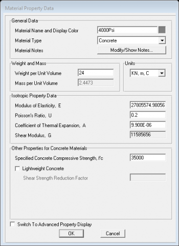
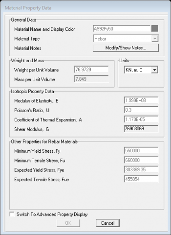
Figure 5. Material property data of the suspension bridge model
The analysis of this study is done with SAP2000 according to [10]. The previous applications of SAP2000 have shown that it can be the most integrated, productive and practical general purpose structural program.
From a simple small 2D static frame analysis to a large complex 3D nonlinear dynamic analysis, SAP 2000 is one of the easiest, most productive solutions for structural analysis and design. Figure 5 shows the window of this software.
4.2 Superstructure loading
In order to analyse the model in SAP2000 it should define the loading and all the parameters of the project as following:
Design load: dead-weight of the 500 meter, secondary-dead load is 59250 kN.
Total vertical dead load=59250 kN.
Girder:
Single column:
Column cross sectional area (Pier 1) = (13.5×3.5×32) m
Column cross sectional area (Pire 2) = (2.25×3.5×68) m
4.2.1 Live load from the superstructure
Maximum= 270.5 kN
Minimum= 0.0 kN
Given:
Multiple Columns Bent: R = 5 (Treat as a wall-type pier).
The bridge is a triple span suspension bridge with a length of 250+500+250 meters, the total length of 1000 meters. H-shaped concrete towers at a height of 68 m. The height from sea level to the underside of the deck is about 32 meters to allow container ships to pass safely under the bridge.
4.2.2 Modeling and analysis
Using the SAP program, all bridge beams, suspension cables and other small members are designed with a bridge slab section width of 9 meters. Vertical struts are placed in suspension positions, and the instant struts are placed along the edges where the surface sections will join to ensure that the model correctly matches the behavior of the bridge.
4.3 Suspension bridge material property
From the file menu, choose a new model, and after choosing a cable bridge, the boundary conditions information and dimensions of the bridge and the layout of the suspension bridge model after simulation in SAP program are defined. Figure 5 shows material property data by which all the required input information will be entered like material type, unit weight of concrete, modulus of elasticity etc. all these information was according to the design in AASHTO code.
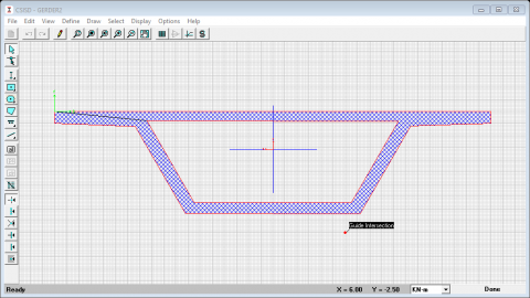
Figure 6 shows the section property data of the girder and it is simulated in the software according to AASHTO code which represent the standard girder for this code.
The seismic load pattern by which the eccentricity ratio is 0.05 and seismic zone factor is 0.075. The factors are taken as the zone suitable to country of project.
Figure 6. Girder section of the suspension bridge model
While Load Case Date-Moving Load: General Vehicle Data are taken into consideration by simulating them as a point load by considering the accel loads applied on the bridge. Load Combination Data and moving loads are necessary to take into consideration by which scale factor and reduction scale factor can be stated. The bridge dead loads were applied as well as live loads and their distribution, and the analysis was performed in the presence of seismic and moving loads. After running the program and find the deformed shape.
4.4 Design and analysis of the supported bridge loadings
The data of loadings and dimension details which is necessary for the analysis are taken as follows:
Superstructure loading:
Design load: dead-weight of the 500 meter is Secondary-dead load is 59250 kN.
Total vertical dead load=59250 kN.
Dimensions of substructure of the bridge:
(Pier 1)=(13.5×3.5×32) m
Live load from the superstructure:
Maximum=270.5 kN
Minimum=0.0 kN
Given:
The bridge is a span suspension bridge with a length of 250 + 500 + 250 meters, as a total length of 1000 meters. The height from sea level to the underside of the deck is about 32 meters to allow container ships in the world to pass safely under the bridge.
4.5 Analysis of supported bridge
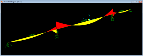
From the file menu, choose a new model, and after choosing a cable bridge, the same previous procedure is repeated but with supported bridge model as mentioned in the previous sections. The bending moment and shear diagram including the maximum moments and shear in the middle and supports of spans are shown in Figure 7. By which the maximum value of moments is located in the middle and maximum shear is in the supports. Deformed shape and resultant shear of the suspension bridge are shown with about 58444 kN and moment is about 43280 kN.m as shown in Figures 8 and 9.
Figure 7. Bending moment and shear diagrams of the supported bridge model
Figure 8. Deformed shape of the supported bridge model
Figure 9. Bending moment diagram of the supported bridge model
The two models were taken with the same girder and dimensions but the style is different to find which style is better. The results are discussed based on the manual calculations which based on the AASHTO code, which is the most widespread used code for designing and analyzing bridges. By knowing the resistance of the bridge to the impacted loads, it is found that the suspended bridge could be better, more appropriate and safer for large spaces (long girder span), unlike the supported bridge, which is not suitable for large spaces. Many researchers have studied the bridge design and the style of design due codes, external effects and environments [11-14]. The design of the bridge style and its effect on bridge stability have been studied [15].
Therefore, the results of the suspended bridge were discussed with the supported bridge according to the AASHTO Code. The calculations show that the moments of both bridges are close, which the suspended bridge has a value equal to 403966 kN.m as shown in Table 1, while the moment of the supported bridge is equal to 403968 kN.m as shown in Table 2. This means that the ratio is approximately 0.005%.
Table 1. The results of loading and moment of suspension bridge according to AASHTO code
|
AASHTO Code: Suspension Bridge |
|
|
Mu (KN.m) |
Pu (KN) |
|
403966 KN.m |
292578.15 Kn |
Table 2. The results of loading and moment of supported bridge according to AASHTO code
|
AASHTO Code: Supported Bridge |
|
|
Mu (KN.m) |
Pu (KN) |
|
403968 KN.m |
340773 Kn |
The shear is calculated according to the AASHTO Code with a value equal to 80664.5 kN for both bridges. Given that both bridges can take the same live loads and dead loads in terms of self-weight and additional loads [16], i.e., at a rate of 100%. The ratio, pu, which represents the axial loads was found to be equal to that of the suspended bridge 340773 kN. For the reinforced bridge, it has a value of 292578.1 kN. This means that the axial loads for the suspension bridge are greater than those of the supported bridge by approximately 14%.
Likewise, with respect to the difference of the reinforcing steel area, the values are equal with respect to 100%. The area of the reinforcing steel is equal to 5434 cm². Through the results of the SAP2000 program are shown in Tables 3 and 4, it is shown that the moment at the supported bridge equal to 445498.8 kN.m slightly greater than the moment of the suspended bridge, which is equal to 432807.1 kN.m, i.e. a ratio of approximately 3%. The shear values were also close, as the shear for the supported bridge was 59526.3 kN, which is slightly greater than the shear for the suspension bridge of 58443.6 kN, i.e. a ratio of approximately 2%. After comparing the results of both bridges according to both methods, it can be said in general that the results of both methods are very close. This means that there is a slight difference in moment values according to the AASHTO Code and the SAP2000 program. The proportions were approximately (6-9)%. As for shear for both methods, the values for the suspension bridge were greater than those of the supported bridge. The difference was about (27-26)%.
Through the results of the SAP2000 program are shown in Tables 3 and 4, it is shown that the moment at the supported bridge equal to 445498.8 kN.m slightly greater than the moment of the suspended bridge, which is equal to 432807.1 kN.m, i.e. a ratio of approximately 3%. The shear values were also close, as the shear for the supported bridge was 59526.3 kN, which is slightly greater than the shear for the suspension bridge of 58443.6 kN, i.e. a ratio of approximately 2%.
After comparing the results of both bridges according to both methods, it can be said in general that the results of both methods are very close. This means that there is a slight difference in moment values according to the AASHTO Code and the SAP2000 program. The proportions were approximately (6-9)%. As for shear for both methods, the values for the suspension bridge were greater than those of the supported bridge. The difference was about (27-26)%. The following Tables show the difference of results moments, shear, loading, deflection and steel area using AASHTO and SAP program for the both models. Table 5 shows the summary results of comparison between AASHTO code and SAP program for the two models. It should be mention that SAP is depending on AASHTO code in the analysis but firstly the software didn’t give option to use it during the procedure of the analysis secondly SAP software is designed to solve the problems according to the finite element analysis which is not considered in AASHTO code.
The limitation and future research direction is to develop or propose new methods in the design of prestressed bridges so that the other researchers can have a benefit of these methods and give them the correct choice to choose the better ones.
Table 3. The results of moment and shear of suspension bridge according to SAP program
|
SAP Program Suspension Bridge |
|
|
Moment (KN.m) |
Shear(kN) |
|
432807.14 kN.m |
58443.573 KN |
Table 4. The results of moment and shear of supported bridge according to SAP program
|
SAP Program: Supported Bridge |
|
|
Moment (KN.m) |
Shear(kN) |
|
445498.81 kN.m |
59526.298 Kn |
Table 5. The final results with percentage difference results for suspension bridge and supported bridge
|
1. Results of the AASHTO code and the results of the SAP program |
||
|
percentage difference results |
SAP Program |
AASHTO Code |
|
|
Suspension Bridge |
Suspension Bridge |
|
6.66% |
Moment = 432807.14 kN.m |
Moment = 403966 KN.m |
|
27.55% |
Shear =58443.573 KN |
Shear =80664.5 KN |
|
|
SAP Program |
AASHTO Code |
|
|
Supported Bridge |
Supported Bridge |
|
9.32% |
Moment =445498.81kN.m |
Moment =403968 KN.m |
|
26.2% |
Shear =59526.298 KN |
Shear=80664.5 KN |
|
2. The results of the suspension bridge and the bridge supported by the AASHTO code |
||
|
|
AASHTO Code |
AASHTO Code |
|
|
Supported Bridge |
Suspension Bridge |
|
|
Total Dead Load |
Total Dead Load |
|
14.18% |
155538 kN |
181242 Kn |
|
|
Factored Axial Load For Critical Case |
|
|
14.14% |
PU=292578.15 Kn |
PU= 340773 KN |
|
0.1% |
Moment =403968 KN.m |
Moment =403966 KN.m |
|
0.0% |
Shear=80664.5 KN |
Shear=80664.5 KN |
|
0.0% |
As=5434 cm² |
As=5434 cm² |
|
0.0% |
Deflection=7.78× $10^{-6}$ m/KN |
Deflection=7.78× $10^{-6}$ m/kN |
|
3. The results of the suspension bridge and the supported bridge SAP program |
||
|
|
SAP Program |
SAP Program |
|
|
Supported Bridge |
Suspension Bridge |
|
2.85% |
Moment =445498.81kN.m |
Moment =432807.14 kN.m |
|
15.68% |
Deflection=0.04838m |
Deflection=0.05738m |
|
1.82% |
Shear =59526.298 KN |
Shear =58443.573 KN |
After performing the calculations according to the AASHTO Code and the SAP2000 program, and by using two models of different bridges, the following conclusions were drawn:
(1) Notice that the torque moment according to the program has a value that is slightly greater than the torque for the AASHTO Code, i.e. the ratio is approximately (6-9)%.
(2) As for the shear, the values were in contrast to the torque values, meaning that the calculations according to the AASHTO Code are greater than the shear values according to the SAP2000 program. The difference ratio was approximately (26-27)%. Given that the SAP2000 program deals with an integrated model unlike manual calculations, this would lead to the fact that the SAP2000 program is more accurate and more reliable in bridge analysis.
(3) As for the deviation, the results of the SAP2000 program were slightly greater than those of the AASHTO Code, considering that the SAP2000 deals with an integrated model and with the most accurate details, unlike the AASHTO Code. The difference ratio was about 99%.
(4) Through all these results, it can be said that the supported bridge is not suitable for large spaces compared to the suspension bridge, which the latter is considered better and safer for large spaces, depending on the SAP2000 program. And the vice versa in AASHTO code, this does not mean the supported bridge is suitable for large spaces according to the AASHTO code, because with the design of the suspension bridge, the cables are not taken into consideration, which is an important part in the design of the suspension bridge.
Data Availability
The model of the bridge taken from a bridge constructed in Basrah city in the south of Iraq which connect the two sides of Shat Al Arab river. This bridge is constructed as suspension bridge with three continuous spans, the middle span is with length of 500 m and the both two other sides are with 250 m length. The dimension and all other specification of the models used in this study are taken similar to the above bridge.
[1] Billington, D.P. (2020). Bridge Engineering. Brittanica.
[2] Garlich, M.J., Pechillo, T.H., Schneider, J.M., et al. (2015). Engineering for Structural Stability in Bridge Construction (No. FHWA-NHI-15-044). United States. Federal Highway Administration. Office of Bridge Technology.
[3] Transportation Officials. Subcommittee on Bridges. (2007). AASHTO Load and Resistance Factor Design Movable Highway Bridge Design Specifications. AASHTO.
[4] Manual of Design Criteria for Bridges and Other Structures. The State of Queensland (Department of Transport and Main Roads), 2021.
[5] Sultan, H.K., Mohammed, A.T., Qasim, O.A., Maula, B.H., Aziz, H.Y. (2020). Ductility factor evaluation of concrete moment frame retrofitted by FRP subjected to seismic loads. International Review of Civil Engineering (I. RE. CE), 11(6): 275-282. http://dx.doi.org/10.15866/irece.v11i6.18670
[6] Qasim, O.A., Sultan, H.K. (2020). Experimental investigation of effect of steel fiber on concrete construction joints of prism. In IOP Conference Series: Materials Science and Engineering, 745(1): 012170. http://dx.doi.org/10.1088/1757-899X/745/1/012170/
[7] Sultan, H.K., Alyaseri, I. (2020). Effects of elevated temperatures on mechanical properties of reactive powder concrete elements. Construction and Building Materials, 261: 120555. https://doi.org/10.1016/j.conbuildmat.2020.120555
[8] Manual, Design Criteria for Bridges and Other Structures, 2020.
[9] Al Basrah Bridge, Bridges in Basrah city-Iraq photographed, 2017.https://www.demiranda.it/?portfolio=cable-stayed-bridge-over-shatt-al-arab-river-al-basra-iraq-work-progress.
[10] Aziz, H.Y., Maula, B.H. (2018). Estimation of negative skin friction in deep pile foundation using the practical and theoretically approaches. Journal of Engineering and Applied Sciences, 13(10): 3340-3349.
[11] Aziz, H.Y., Abd-Noor, A.A. (2016). Comparison of high speed railway bridge substructures. African Journal of Engineering Research, 4(2): 36-42.
[12] Aziz, H.Y., Ma, J. (2012). Experimental and theoretical static analysis of high-speed railway bridge settlement for deep soft soil. The Open Construction and Building Technology Journal, 6(1): 17-31. https://doi.org/10.2174/1874836801206010017
[13] Aziz, H.Y., Ma, J. (2011). Design and analysis of bridge foundation with different codes. Journal of Civil Engineering and Construction Technology, 2(5): 191-118. https://doi.org/10.5897/JCECT.9000012
[14] Aziz, H.Y., Ma, J., Mohammed, A.A., Liu, N. (2011). Design of substructure bridge with different codes and analysis manually and by using Plaxis program 3D. In ICTE 2011, 517-523. https://doi.org/10.1061/41184(419)251
[15] Mascolo, I., Modano, M. (2020). Optimisation of suspended-deck bridge design: A case study. Australian Journal of Structural Engineering, 21(3): 244-253. https://doi.org/10.1080/13287982.2020.1778433
[16] Parsons Brinckerhoff. (2009). Design Guidelines for High-Speed Train Aerial Structures TM 2.3.3. California High-Speed Train Project. http://www.tillier.net/stuff/hsr/TM-2.3.3-HST-Aerial-Structure-R0-090602.pdf.