Lubna Thamer* | Hussein Shaia
© 2021 IIETA. This article is published by IIETA and is licensed under the CC BY 4.0 license (http://creativecommons.org/licenses/by/4.0/).
OPEN ACCESS
The term "reinforced soil" refers to a composite material with high tensile-strength components that enhance the soil's tensile strength. One of the most common kinds of geosynthetic fabric utilized for soil reinforcement is geotextiles. This article investigates woven geotextile's potential benefits in enhancing the maximum load-carrying capacity of footings resting upon silty sand soil. The foundation was constructed of a 10 mm thick strong carbon steel plate of 100 mm×100 mm. The factors examined in this research were the first geotextile layer's depth, the geotextile layer's width, the number of layers of reinforcing material, and the vertical spacing between geotextile layers. The impact of geotextile strengthening configurations on the load-carrying capacity of strengthened soil foundations was also studied. The results of the experiments indicated that geotextile reinforced soil could help to grow the soil bearing capacity. The testing findings revealed that the system with three geotextile layers, 0.25B vertical distance among geotextile layers, and a geotextile width of 5B, B denotes the plate's width, achieves the most significant bearing capacity. The test findings also revealed that the reinforcement configuration greatly impacted the reinforced silty sand on the foundation's behavior.
bearing capacity, woven geotextile, silty sand soil, plate load test, configuration effect, square footing, model tests, reinforcement
Soil is the most common and least expensive resource utilized as a building material. However, it occasionally suffers from a lack of suitable engineering qualities. In this respect, several academics are constantly working to develop new ways to improve the features. Furthermore, introducing new construction materials and procedures will increase their qualities and make the soil appropriate for various building operations [1].
"Reinforced Soil" or "Reinforced Earth" refers to a building technology created by combining soil with reinforcement. It has gained popularity due to its wide range of uses. Henry Vidal, a French engineer, was the first to pioneer the approach [2]. Engineers have been researching the usage of geosynthetics to raise the efficiency of shallow foundations over the last two decades. Geosynthetics strengthening is a cost-effective solution in the case of bad fringe soil conditions. ASTM D4439 describes geosynthetic as a planar material composed of polymers combined with the ground, soil, rocks, and various geotechnical engineering-related components in a man-made construction system or program. Geosynthetics might help improve soil quality, boost the project's safety factor, and lower the project's construction costs. One of the most common types of geosynthetics is geotextiles. A geotextile is a permeable geosynthetic constructed of textile fibers [3]. The good effect of a geosynthetic additional is primarily dedicated to how it is employed as reinforcement. For instance, the same geosynthetic material will provide various strength gains in various forms when utilized in planar layers, geocells, or discrete fibers containing similar materials. This disparity in strength is mostly due to the diverse failure mechanisms in soil strengthened with geosynthetics in various forms [4]. Many researchers have investigated the favorable impacts of adopting geosynthetic soil reinforcement. Banquet and Lee published the first systematic research on employing metallic strips to improve strip foundation bearing capacity [5, 6]. Since then, much study has been devoted to recognizing the conduct of strengthened soil bases and the impacts of various factors on their bearing capacity, such as the Refs. [7-14]. Akinmusuru and Akinbolade [15] study the effect of the initial reinforcement layer's height as well as the total number of layers of strengthening on reinforced sand. The tests were carried out on square foundations with woven strips utilized as re-enforcing components. For sand strengthened with three reinforcing layers, the number of reinforcing layers with the best performance was determined to be (3), and 0.5B was the ideal depth for the first layer of reinforcement. The effect of numerous factors on the bearing capacity of geogrid and geotextile reinforced sands was studied. They demonstrated that the approach for geotextile enforcement is founded on the friction between sand and geotextiles. On the other hand, they depend on the interlocking between sand and geogrid. Yetimoglu et al. [16] evaluated the bearing capacity of rectangular sample foundations lying upon sand enhanced with one or more multilayers of geogrids. They found that 0.3B was the best reinforcing depth for sand strengthened with one layer of geogrid. Gabr et al. [17] investigated the stress distribution in geogrid strengthened sand using plate load experiments with pressure cells. The results demonstrated that the incorporation of the reinforcement resulted in superior stress attenuation. Sitharam and Sireesh [18] have carried out laboratory model testing to assess the bearing capacity of an embedded sand bed supported circular foundation strengthened with many geogrids layers. The test findings indicate that with the foundation's embedment depth ratio, the ultimate bearing pressure increases. Latha and Somwanshi [19] studied the bearing capacity of foundations onto geosynthetic reinforced sands and the effects of different reinforcement factors such as geosynthetic material type and tensile strength- the quantity of reinforcement- design and arrangement of geosynthetic sheets under the foundation on the improvement of the footings' bearing capacity. Results indicate that the successful reinforcement depth was twice as wide as the footing; 1/2 the width of the footing is the ideal spacing of geosynthetic layers. Abu-Farsakh et al. [20] conducted a study on the influence of numerous parameters that refer to their efficiency utilizing different experimental tests. They utilized three different geogrid types and one geotextile type. The findings of the experiments have indicated that the strengthening configuration had a significant influence on the actions of the improved sand foundation. Sand strengthened with geogrids and geotextiles was more effective than geogrids or geotextiles strengthened alone. Kazi et al. [21] examined the effect on sand beds of one layer of woven-geotextile reinforcements with wraparound ends. The model test findings revealed that as D/B rises, regarding both reinforced instances without and with wraparound ends during all densities relative, qRu (maximum load-bearing capacity of strengthened soil) rises until D/B=0.3, then declines with a rise in D/B. By comparing reinforcement with wraparound ends to reinforcement without wraparound ends for D/B=0.3, for (Dr) 50, 70, and 90 percent, the wraparound ends result in qRu improvements of about 1.25, 20, and 57 kPa, respectively. Tavangar and Shooshpasha [3] investigated the influences of using nonwoven-geotextile to increase the maximum bearing capacity of footings lying on medium-density sand. Their test results demonstrated that the system with 0.3B vertical spacing across geotextile layers, and four geotextile layers have the highest bearing capacity. Panigrahi and Pradhan [22] have used geo jute (gunny bags) as a geotextile to increase soil bearing capacity. The experiments showed that the most effective zone of reinforcement was at a depth of 0.5B. Regardless of the size of the footing, the maximum benefit was achieved at the optimum reinforcement size of 3.5Bx3.5B. Several studies show the influence of different parameter types of geosynthetic materials. However, there are no studies on silty sandy soils related to improving square foot bearing capacity and geotextile system. This study discusses the results of laboratory model experiments on square footing maintained by silty sand soil with and without geotextile strengthening. The major objectives of this paper are to assess the achievement of geotextile layers in enhancing the bearing capacity of the square foundation and investigate the effect of various reinforcing factors on overall footing achievement improvement. The parameters examined in the model testing involve top layer spacing (U), reinforcing layer width (W), the number of layers of reinforcement (N), the vertical distance between reinforcement layers (h), and reinforcing layer configuration.
2.1 Setup for the test
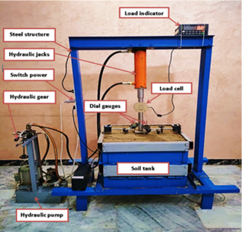
The Experimental setup utilized in this investigation is presented in Figure 1. The system consists of a box with dimensions of 600 mm × 600 mm and a height of 400 mm. The plates that form the bottom and sides of the box are 6 mm thick, making them robust enough to resist the loading pressure. The box's base is created from solid steel with measures of 800 mm in width and 1100 mm in length, and it's attached to a loading frame. The steel container comprises a 6 mm steel plate bolted together and welded to the steel plate with a steel angle of (75×75×6) mm. The loading frame is made up of two columns and a loading platform. In addition, in this research, 100×100 mm square plates with a thickness of 25mm were used. The footing was placed so that the center of the foundation coincides with the center of the bedding soil and is in contact with the top surface of the ground. These dimensions were determined using the ASTMD-1196 standard for plates. It is necessary to measure the footing's settlement using two dial gauges with a range of 25 mm, and an accuracy of 0.01 mm hung on reference beams. For the plate load test, a loading jack with a capacity of 10 tons was employed.
Figure 1. Experimental setup
2.2 Materials for the examination
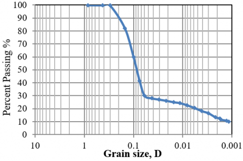
The soil sample for this research was taken in the Almuhia region, Al-Ameed Residential Complex in Nasiriyah, Iraq Figure 2. The soil samples are taken from a depth of (1.0-1.5) m below the existing ground level. Sieve analysis and hydrometer were also performed on the soil sample to calculate the distribution curve of particle sizes, as illustrated in Figure 3. According to the unified soil classification system (USCS), the soil is categorized as silty sand soil (SM). The engineering properties of the soil are given in Table 1.
Table 2 lists the mechanical and physical characteristics of the woven geotextile utilized in this investigation.
2.3 Soil preparation
Within the steel test box, the soil was layered and compacted. Іn οrdеr tο еnѕurе thе асhіеvеmеnt οf а unіfοrm ѕοіl dеnѕіty wіthіn thе ѕοіl rеѕеrvοіr іn сοnfοrmіty wіth thе fіеld ѕοіl dеnѕіty, the box was divided into four layers, еасh lаyеr wіth а hеіght οf 100 mm, аnd thе vοlumе οf еасh lаyеr wаѕ fixed аt 0.036 m3. Each layer's thickness ranged between 25 and 100 millimeters, based on the reinforcing spacing. The soil and water for the empirical samples were mixtures by hand. The quantity of soil required for each layer was first determined. Then the soil was put into the box, leveling, and compacting using a 200 mm×200 mm plate and with a weight of 10 kg under a number of blows which given equipollent density to the soil in the field. This procedure is carried out for each layer until the soil reaches the desired depth of (450) mm. Before that, the tank's sides were smoothed out by coating them with a lubricating gel in order to minimize the impacts of boundary effects. After the final layer was completed, the surface was leveled, and the foundation was perfectly centered on the loading jack to prevent eccentric loading. The footing had been loaded by an electric hydraulic jack supported against a reaction frame. The load transmitted to the footing was measured using a pre-calibrated load cell with a capacity of 5 tons. The load was applied in small increments. Until the footing settling has stabilized, each successive load increase was kept constant. The model's geometry is shown in Figure 4. It should be noted that "U," "N," "W," and "h" refer to the height of the first geotextile layer, the number of layers geotextile, the width of the geotextile layers, and the vertical spacing among geotextile layers, respectively.
Table 1. Soil properties
|
Soil Property |
Specific gravity (Gs) |
D10 (mm) |
D60 (mm) |
D30 (mm) |
LL |
PL |
Cohesion (kPa) |
friction angle ∅° |
$Ɣ_{field}$(kN/m3) |
Wc % |
Sand % |
Fines content % |
Soil classification |
|
Value |
2.58 |
.0011 |
0.1 |
0.061 |
24.6 |
21 |
7.06 |
27 |
17.88 |
14 |
58.7 |
41.3 |
SM |
Table 2. The characteristics of woven geotextiles
|
Elongation% |
Tensile strength (Kn/m) |
Thickness(mm) |
Mass / unit area (gr/m2) |
|
15 |
80 |
1.1 |
370 |
Figure 2. Site of study
Figure 3. The soil particle size distribution
Figure 4. The model's geometry
The ultimate bearing capacity is defined in this paper as the foundation stress related with a10% settling of the plate width in all plate load testing [23]. Additionally, the bearing capacity ratio (BCR) of all plate load experiments was examined. This ratio is described as the maximum bearing capacity of a square base on strengthened soil divided by the ultimate bearing capacity of the same base on not supporting ground.
3.1 Influence of the first geotextile layer
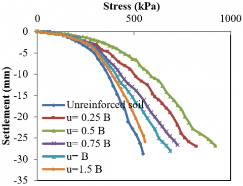
Figure 5. Curves of stress settlement for model footing tests using one layer of geotextile with varying top layer spacings
A single-layer geotextile system was employed to ascertain the optimal thickness of the first geotextile layer (U) and ensure that other factors do not affect the ultimate bearing capacity. To ensure uniform qualification and mitigate the impact of layer width on reaching the optimal height of the first layer, the layer's width was kept constant and similar to the box's width [24]. The load settlement curves for model footing testing using one layer of geotextile at various top layer spacings are shown in Figure 5.
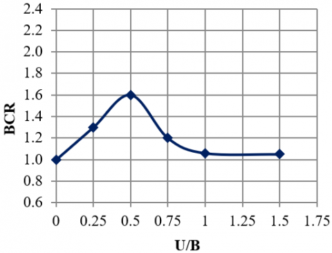
Figure 6. Bearing capacity ratio BCR with U/B for one layer of geotextile
Figure 6 demonstrates that as the top layer spacing ratios (U/B) increase, the BCR increases until it reaches an ultimate value at U/B=0.5, and then it declines. The upper layer distance ratio (U/B) is the relationship between top layer spacing (U) and footing width (B). The best position for the upper layer is determined to be around 50 mm, or 0.5B. The rise and decrease in the ratio of bearing capacity concerning increasing depth might be related to the theory of stress distribution. When a load is applied to the foundation depth, the load is dispersed within the impact zone of 2.0B depth. At the mid-height of the effect zone, 1.0B, the load intensity is high. But, in the current investigation, the load intensity is high in the 0.25B to 0.75B range, with a maximum value of 0.5B achieved using reinforcement. This result is comparable to those made in the works [22, 25]. Panigrahi & Pradhan [22] found that the highest amount of BCR was gained at a depth of 0.5B for square footing on one geotextile layer reinforced sand. Shin & Das showed that the optimal positioning of the top layer for three geogrid layers was around 0.4B for strip footing on clay. In contrast, Puroshothama and Ramaswamy [26] achieved a maximum BCR at u/B=0.5 using a 40 mm diameter circular foundation on clay strengthened by a single layer of reinforcement. This disparity in the best position for upper layer reinforcement might be due to various soil and reinforcing characteristics from different studies.
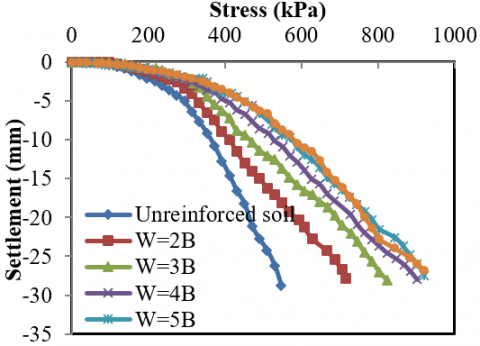
3.2 The influence of the geotextile layer's width
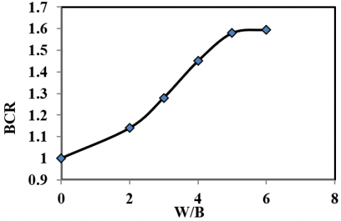
The optimal geotextile layer width (W) for silty sand strengthened with a single layer of geotextile and a U/B of 0.5 is illustrated in Figure 7. The bearing capacity values were nearly equal after W/B=4, as shown in Figure 6, which can be associated with the geosynthetics mechanism. The geotextile's tensile behavior, generally, can considerably reduce the applied stress to the soil [27]. The term "optimal reinforcement width " refers to the truth that just the part of strengthening located inside the shear zone under the footing will have its tensile strength crowded efficiently. To give a pulling resistance to the reinforcement, it is necessary to have some extra length outside the shear area as an anchoring. As a result, the optimal reinforcement width equals the sum of the shear zone and anchoring zone widths on both sides. Any reinforcement width more than this best value is useless and will not consequence any further increase in the bearing capacity of the footing [28]. Figure 8 depicts a graph illustrating the variance in BCR with the width of reinforcement (w), which is changed between 2B and 6B in different tests can be observed If rises as the reinforcement width ratio increase up to w/B 4.0, at which point the impact of reinforcement width on the enhancement of square footing bearing capacity is virtually insignificant. According to Lee et al. [29], the reinforcement should be 5-6 times the width of the footing. Sitharam and Sireesh [18] found that the optimal width of reinforcements for circular footings is roughly four times the footing's diameter, based on laboratory model testing. Based on a regression model, Bera et al. [30] suggested an optimal reinforcement width of (5-7) times the footing's width for square footings on reinforced pond ash. Latha and Somwanshi [31] studied sand beds reinforced with planar geogrids and found no significant increase beyond a reinforcement width of (4) times the footing width.
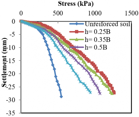
3.3 Effects of reinforcement layer vertical spacing
Figure 7. Stress settlement curves for model foundation trials with a single layer of geotextile reinforced with various widths
Figure 8. Impact of W/B on bearing capacity ratio (BCR)
Figure 9. Stress settlement curves for three-layer geotextile model footing tests with various vertical spacing between reinforcing layers
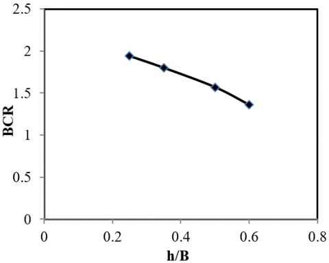
Figure 10. The change in the bearing capacity ratio (BCR) with h/B
The effect of vertical reinforcing layer spacing was investigated in this phase using the optimum first layer distance (U=0.5B) and geotextile width (w=5B) from prior experiments. Moreover, three layers of geotextile were used. As demonstrated in Figure 10, the spacing between layers (h/B) equal to 0.25B has the highest bearing capacity, followed by 0.35, 0.5, and 0.6. Curves, as illustrated in Figure 9, do not have a maximum value. In other words, the tensile strength of the geotextile did not reach its maximum. Thus, geotextile tensile strength is not the influential factor in failure. Vertical distance has a non-independent impact. Instead, it is determined by a top layer spacing (U) and the number of layers (N). Guido et al. [32] have highlighted that the impact of vertical spacing on the bearing capacity is difficult to completely understand without taking other influencing variables into account. However, the BCR for the silty sand and geotextile reinforcement evaluated in this research is more significant when the spacing is smaller. The findings also indicate no considerable difference in the initial stages and that curves overlapped in some instances; consequently, differences between reinforcement components will be identified at high displacement. Guido et al. [33] found similar findings on geo-grid reinforced sand, as did the Ref. [34] on geo-grid reinforced clay. Yetimoglu et al. [16] found an optimal vertical distance of strengthening layers for maximum bearing capacity when utilizing rectangular foundation on geogrid reinforced sand. Based on their research, Vertical distance was about 0.2B for strengthened sand with 4 layers of reinforcement and an upper layer spacing of 0.3B.
3.4 The influence of geotextile layer number
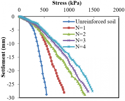
The ideal number of geotextile layers is calculated using the optimal U/B, W/B, and h/B values established in the preceding sections, as shown in Figure 11. In another term, the ideal number of geotextile layers is determined for geotextile reinforced silty sand with a U/B ratio of 0.5, a W/B ratio of 5, and an h/B ratio of 0.25. As anticipated, with an increase in the number of strengthening layers, the bearing capacity improved. However, the importance of an added reinforcement layer reduced as the number of layers grew. Figure 11 compares models' findings with one, two, three, and four layers of geotextile to the equivalent non-reinforced model.
It should be noted that the distance between the geotextile layers is 25 mm. As seen in the Figure, the ultimate bearing capacity rises as the number of geotextile layers rises. This implies that for settlement to occur, a significant amount of soil must move. As a result, resistance to soil displacement rises, resulting in reduced settlement.
Figure 11. Stress-settlement curves for model foundation testing using various geotextile layer numbers
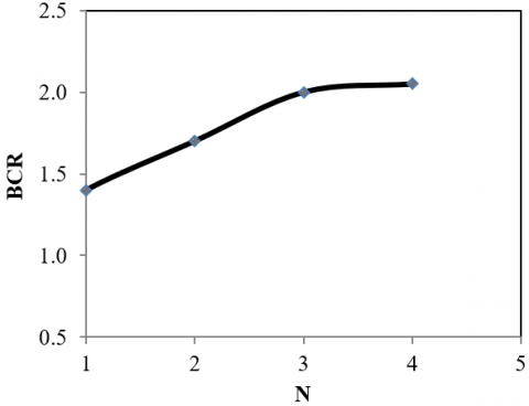
Figure 12 shows that the BCR rises with N and seems to become nearly constant after N=3 or has a negligible effect on the maximum bearing capacity of the soil at 1.0B depth. Impact depth (d/B) is defined as the depth below the footing under which the inclusion of an additional reinforcement layer contributes significantly to the BCR increase. Similar to these results, Guido et al. [33] found that geogrids and geotextiles under 1.0B could not increase sand capacity for bearing. According to the findings [35], the impact depth was about 1.2B. The information in Refs. [31, 36] indicated that influence depth was approximately 2.0B. Sakti and Das [37] found that geotextiles applied under 1.0B did not enhance clay's bearing capacity. So in this study, the optimal number of reinforcement was (N=3).
Figure 12. BCR with N relationship
3.5 Configuration of geotextile layer
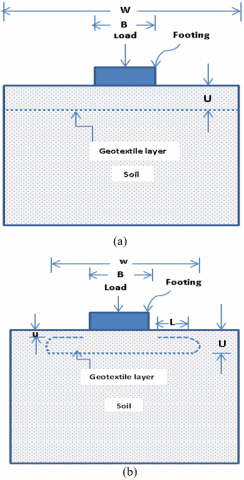
This step investigated the effects of geotextile reinforcement configurations on the bearing capacity of reinforced soil foundation structures. A series of laboratory tests were carried out using square footing with one layer of the woven-geotextile reinforcement with wraparound ends. The geotextile reinforcement (w) width was recorded at 600 mm, similar to the box's width as shown in Figure 13a. Figure 13b shows how the geotextile with wraparound ends was put in the shape, with the lap (L) width maintained at 80 mm.
Figure 13. (a) Foundation resting on the geotextile reinforced soil without wraparound ends and (b) A foundation resting on the geotextile-reinforced soil with wraparound ends
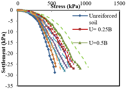
The change in pressure (q) with settling for reinforced soil is shown in Figure 14. With a single geotextile layer reinforcing applied at various depths U/B=0.25,0.5,0.75,1, and 1.5 from the footing's base with the given details: W/B = 6 for reinforcement without wraparound ends Figure 13.a. w/B = 4, L/B = 0.8, u/B = 0.05, 0.3, 0.55, 0.8, and 1.3 for wrapped ends with U/B = 0.25, 0.5, 0.75, 1 and 1.5, respectively. In Figure 14, As the pressure rises, it is seen that the footing settlement continues to rise. For every load, the settlement is less for reinforced cases without and with wraparound ends when U/B=0.5. In other words, for any settlement, reinforced soil carries a greater load than unstrengthened soil. Additionally, it can be observed that the wraparound ends provide an extra bearing capacity increase above the strengthened case without a wraparound.
The connection between ultimate bearing capacity and embedment depth ratio (U/B) for strengthened soil is shown in Figure 15. The qRu values for U/B=0 represent the unreinforced condition. As U/B rises, it is seen that qRu continues to rise until U/B=0.5; afterward, it diminishes as U/B increases for both strengthened instances without wraparound ends and supported cases with wraparound ends. According to the previous discussion, any given load-bearing pressure results in much less footing settling than in the case of reinforcement without wraparound ends. The improvement is due mostly to the confinement effect [38-40] caused by the wraparound ends.
Figure 14. Stress versus settlement effect of depth of reinforcement
Figure 15. The connection between ultimate bearing capacity and embedment depth ratio (U/B)
This research established a set of laboratory-scale foundation tests on geotextile unreinforced and reinforced foundations to determine the possible advantages of employing reinforcement to raise the bearing capacity and decrease the settling of shallow foundations on silty sand soils. The findings indicate that the maximum bearing capacity of woven geotextile strengthened silty sand in all instances is greater than that of unreinforced silty sand.
The research work has been carried out at Soil Mechanics Laboratory at the Department of Civil Engineering, University of Thi-Qar, Iraq University E-mail: university.of.thiqar@utq.edu.iq.
The authors also express sincere thanks to the referees for their valuable suggestions in the improvement of the paper.
|
U/B |
The ratio of the depth of the first geotextile layer to the width of the plate. |
|
W/B |
The ratio of the geotextile width to plate width |
|
h/B |
Vertical spacing between geotextile layers / plate width |
|
N/B |
The ratio of number of geotextile layers to the plate width |
|
BCR |
The ratio of reinforced to unreinforced soil carrying capacity |
[1] Kurre, P., Kumar, M., Praveen, G.V., Heeralal, M. (2017). An inquisitive method of improving California bearing ratio (CBR) value of marginal soil subgrade of flexible pavement construction. International Journal of Civil Engineering and Technology, 8(6): 842-849.
[2] Şadoğlu, E. (2015). Numerical analysis of centrally and eccentrically loaded strip footing on geotextile-reinforced sand. Geosynthetics International, 22(3): 225-234. https://doi.org/10.1680/gein.15.00007
[3] Tavangar, Y., Shooshpasha, I. (2016). Experimental and numerical study of bearing capacity and effect of specimen size on uniform sand with medium density, reinforced with nonwoven geotextile. Arabian Journal for Science and Engineering, 41(10): 4127-4137. https://doi.org/10.1007/s13369-016-2101-y
[4] Nakai, T., Shahin, H.M., Morikawa, Y., Masuda, S., Mio, S. (2014). Effect of reinforcement on bearing capacity of foundations. In Advances in Soil Dynamics and Foundation Engineering, pp. 482-490. https://doi.org/10.1061/9780784413425.049
[5] Binquet, J., Lee, K.L. (1975). Bearing capacity analysis of reinforced earth slabs. Journal of the Geotechnical Engineering Division, 101(12): 1257-1276. https://doi.org/10.1061/AJGEB6.0000220
[6] Binquet, J., Lee, K.L. (1975). Bearing capacity tests on reinforced earth slabs. Journal of the Geotechnical Engineering Division, 101(12): 1241-1255. https://doi.org/10.1061/AJGEB6.0000219
[7] Mandal, J.N., Sah, H.S. (1992). Bearing capacity tests on geogrid-reinforced clay. Geotextiles and Geomembranes, 11(3): 327-333. https://doi.org/10.1016/0266-1144(92)90007-W
[8] Adams, M.T., Collin, J.G. (1997). Large model spread footing load tests on geosynthetic reinforced soil foundations. Journal of Geotechnical and Geoenvironmental Engineering, 123(1): 66-72. https://doi.org/10.1061/(ASCE)1090-0241(1997)123:1(66)
[9] Chen, Q., Abu-Farsakh, M.Y., Sharma, R., Zhang, X. (2007). Laboratory investigation of behavior of foundations on geosynthetic-reinforced clayey soil. Transportation Research Record, 2004(1): 28-38. https://doi.org/10.3141/2004-04
[10] Rethaliya, R.P., Verma, A.K. (2009). Strip footing on sand overlying soft clay with geotextile interface. Indian Geotech J, 39(3): 271-287.
[11] Kolay, P.K., Kumar, S., Tiwari, D. (2013). Improvement of bearing capacity of shallow foundation on geogrid reinforced silty clay and sand. Journal of Construction Engineering, 2013: 1-10. https://doi.org/10.1155/2013/293809
[12] Demir, A., Yildiz, A., Laman, M., Ornek, M. (2014). Experimental and numerical analyses of circular footing on geogrid-reinforced granular fill underlain by soft clay. Acta Geotechnica, 9(4): 711-723. https://doi.org/10.1007/s11440-013-0207-x
[13] Makarchian, M., Badakhshan, E. (2017). Comparison of bearing capacity of footings with same area resting on reinforced sand. GEOMATE Journal, 12(29): 9-16. https://doi.org/10.21660/2017.29.79025
[14] Zhou, B., Wang, H., Wang, X., Ji, J. (2018). Permeability and stability of soil bags in slope protection structures. International Journal of Heat and Technology, 36(3): 1094-1100. https://doi.org/10.18280/ijht.360341
[15] Akinmusuru, J.O., Akinbolade, J.A. (1981). Stability of loaded footings on reinforced soil. Journal of the Geotechnical Engineering Division, 107(6): 819-827. https://doi.org/10.1061/AJGEB6.0001153
[16] Yetimoglu, T., Wu, J.T., Saglamer, A. (1994). Bearing capacity of rectangular footings on geogrid-reinforced sand. Journal of Geotechnical Engineering, 120(12): 2083-2099. https://doi.org/10.1061/(ASCE)0733-9410(1994)120:12(2083)
[17] Gabr, M.A., Dodson, R., Collin, J.G. (1998). A study of stress distribution in geogrid-reinforced sand. In Geosynthetics in Foundation Reinforcement and Erosion Control Systems, 62-76.
[18] Sitharam, T.G., Sireesh, S. (2004). Model studies of embedded circular footing on geogrid-reinforced sand beds. Proceedings of the Institution of Civil Engineers-Ground Improvement, 8(2): 69-75. https://doi.org/10.1680/grim.8.2.69.36369
[19] Latha, G.M., Somwanshi, A. (2009). Bearing capacity of square footings on geosynthetic reinforced sand. Geotextiles and Geomembranes, 27(4): 281-294. https://doi.org/10.1016/j.geotexmem.2009.02.001
[20] Abu-Farsakh, M., Chen, Q., Sharma, R. (2013). An experimental evaluation of the behavior of footings on geosynthetic-reinforced sand. Soils and Foundations, 53(2): 335-348. https://doi.org/10.1016/j.sandf.2013.01.001
[21] Kazi, M., Shukla, S.K., Habibi, D. (2015). An improved method to increase the load-bearing capacity of strip footing resting on geotextile-reinforced sand bed. Indian Geotechnical Journal, 45(1): 98-109. https://doi.org/10.1007/s40098-014-0111-9.
[22] Panigrahi, B., Pradhan, P.K. (2019). Improvement of bearing capacity of soil by using natural geotextile. International Journal of Geo-Engineering, 10(1): 1-12. https://doi.org/10.1186/s40703-019-0105-7
[23] Briaud, J.L., Jeanjean, P. (1994). Load settlement curve method for spread footings of sand. In Vertical and Horizontal Deformations of Foundations and Embankments, 1774-1804.
[24] Mosallanezhad, M., Hataf, N., Ghahramani, A. (2008). Experimental study of bearing capacity of granular soils, reinforced with innovative grid-anchor system. Geotechnical and Geological Engineering, 26(3): 299-312. https://doi.org/10.1007/s10706-007-9166
[25] Shin, E.C., Das, B.M. (1998). Ultimate bearing capacity of strip foundation on geogrid-reinforced clay slope. KSCE Journal of Civil Engineering, 2(4): 481-488. https://doi.org/10.1007/bf02830129
[26] Ramaswamy, S.D., Purushothaman, P. (1992). Model footings of geogrid reinforced clay. In Proceedings of the Indian Geotechnical Conference on Geotechnique Today, 1: 183-186.
[27] Moraci, N., Gioffrè, D. (2006). A simple method to evaluate the pullout resistance of extruded geogrids embedded in a compacted granular soil. Geotextiles and Geomembranes, 24(2): 116-128. https://doi.org/10.1016/j.geotexmem.2005.11.001
[28] Morel, J.C., Gourc, J. P. (1997). Mechanical behavior of sand reinforced with mesh elements. Geosynthetics International, 4(5): 481-508. https://doi.org/10.1680/gein.4.0103
[29] Lee, K.M., Manjunath, V.R., Dewaikar, D.M. (1999). Numerical and model studies of strip footing supported by a reinforced granular fill-soft soil system. Canadian Geotechnical Journal, 36(5): 793-806. https://doi.org/10.1139/t99-053
[30] Bera, A.K., Ghosh, A., Ghosh, A. (2005). Regression model for bearing capacity of a square footing on reinforced pond ash. Geotextiles and Geomembranes, 23(3): 261-285. https://doi.org/10.1016/j.geotexmem.2004.09.002
[31] Latha, G.M., Somwanshi, A. (2009). Effect of reinforcement form on the bearing capacity of square footings on sand. Geotextiles and Geomembranes, 27(6): 409-422. https://doi.org/10.1016/j.geotexmem.2009.03.005
[32] Guido, V.A., Biesiadecki, G.L., Sullivan, M.J. (1985). Bearing capacity of a geotextile-reinforced foundation. In International Conference on Soil Mechanics and Foundation Engineering. 11: 1777-1780.
[33] Guido, V.A., Chang, D.K., Sweeney, M.A. (1986). Comparison of geogrid and geotextile reinforced earth slabs. Canadian Geotechnical Journal, 23(4): 435-440. https://doi.org/10.1139/t86-073
[34] Ingold, T.S., Miller, K.S. (1982). Analytical and laboratory investigation of reinforced clay. In Proceedings of the Second International Conference on Geotextiles, 3: 587-592.
[35] Omar, M.T., Das, B.M., Puri, V.K., Yen, S.C. (1993). Ultimate bearing capacity of shallow foundations on sand with geogrid reinforcement. Canadian Geotechnical Journal, 30(3): 545-549. https://doi.org/10.1139/t93-046
[36] Basudhar, P.K., Saha, S., Deb, K. (2007). Circular footings resting on geotextile-reinforced sand bed. Geotextiles and Geomembranes, 25(6): 377-384. https://doi.org/10.1016/j.geotexmem.2006.09.003
[37] Sakti, J.P., Das, B.M. (1987). Model tests for strip foundation on clay reinforced with geotextile layers. Transportation Research Record, 1153.
[38] Shukla, S.K., Yin, J.H. (2006). Fundamentals of Geosynthetic Engineering-Chapter 4. Taylor & Francis Group, LLC, London, UK.
[39] Shukla, S.K. (2011). Handbook of Geosynthetic Engineering.
[40] Shukla, S.K. (2004). Discussion: Applications of geosynthetics for soil reinforcement. Proceedings of the Institution of Civil Engineers-Ground Improvement, 8(4): 179-182. https://doi.org/10.1680/grim.2004.8.4.179