Neerudi Bhoopal | Dokku Sivanaga Malleswara Rao | Bharath Kumar Narukullapati | Idamakanti Kasireddy | Devineni Gireesh Kumar*
© 2021 IIETA. This article is published by IIETA and is licensed under the CC BY 4.0 license (http://creativecommons.org/licenses/by/4.0/).
OPEN ACCESS
This paper proposed a new topology of a symmetric single-phase multilevel inverter with the smaller number of semiconductor switches and optimized low-frequency control methods to optimize the Total Harmonic Distortion. A nine-level single phase output is obtained by eight number of active semiconductor switches, four diodes and four capacitors from two asymmetrical dc sources. The selected harmonic order in the output voltage is eliminated by the PWM (SHE-PWM) based on selective harmonic elimination. To optimize the switching angles, an ant colony optimization is introduced. The proposed SHE-PWM and ant optimization are implemented and tested for THD on the SIMULINK platform. The proposed approach offers less THD and is best suited to high-power applications with medium voltage.
THD, SHEPWM, ACO, multi-level inverter, optimization, symmetric Inverter
Inverter is a system that converts the acceptable voltage and output frequency from DC to AC. There are some problems in inverters including lower efficiency, high dv/dt, higher power losses and large THD [1]. A multi-level inverter is designed to solve these issues. With a three-level converter, the word Multilevel has begun, the cascaded multilevel inverter is currently in use [2]. The output of the multi-level inverter has lower harmonics than the normal output voltage of the bipolar inverter. Multilevel inverters are mainly known as a clamped diode, Flying condenser, and cascaded MLI [2, 3]. The control scheme of cascaded MLI is simple compared to other MLIs since a clamping diode and a flying condenser are not needed [4]. For more than three decades, multi-level inverters are under research and development, and successful industrial applications have been discovered [5]. Nonetheless, this is still an emerging technology, and many fresh developments have been reported in recent years [6-8]. Multilevel inverters have drawn growing interest, with the key reasons being increasing power levels, improved harmonic performance and reduced emissions of electromagnetic interference (EMI) that can be preserved with several dc stages synthesizing the output voltage waveform [7]. In systems like industrial variable-voltage drives, EVs and photovoltaic networks connected to the grid. The ongoing work offers an alternative to the design of an effective multi-level topology for high and medium-power applications.
Advanced Multi-level inverters now use fewer components and smaller carrier signals as compared with traditional multi-level inverters. A composite topology is presented in this paper having separate level generating part and polarity generating parts [8]. To increase the output of multilevel inverters in hybrid topology, first positive rates are produced with high-frequency switches and then the voltage portion is reversed with low-frequency switches [9-12]. As a result, the control circuit complexity for higher levels is significantly reduced. Selective harmonic pulse width modulation (SHE-PWM) technique with Ant Colony optimization has been used to simulate a single phase 9-level hybrid inverter. The inverter performance is evaluated about harmonic distortion (THD) [13-15]. The purpose of this research is to minimize the THD of output voltage by using low switching frequency PWM (SHEPWM) and optimization algorithm in reduced switch symmetrical 9-level inverter. The harmonic distortion generated by the proposed inverter is significantly lower, around 5% by the results obtained from simulation. This paper is organized as follows. Firstly, introduction to the multilevel inverter literature, Section-2 describes the proposed 9-level symmetric inverter topology, Section-3 presents selective harmonic elimination-based control of proposed inverter, Section-4 presents results & discussions, and finally section-5 concludes the research results.
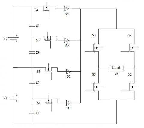
The proposed inverter's schematic design is shown in Figure 1, which consists of two modules, namely a module for level generation and a module for voltage reversal/polarity generation. Polarity generation module is an H-bridge that reverses the polarity of output for each half cycle of operation, whereas the level generating module will generate higher levels from the dc sources that can extend up to ' n ' levels. Symmetric dc sources are used for the inverter input, where each source is divided into two equal parts by using similar condensers to increase the higher output level from less dc sources. A MOSFET is used for the circuit design and the diodes used in the circuit to prevent the short circuit of the sources [16, 17].
Relation between the components used in the circuit design given as follows.
No. of capacitors (Nc) = 2 Nv,
Where, Nv = No. of voltage sources
No. of Switches (Ns) = Nc + 4
No. of diodes (Nd) = Nc
No. of levels (Nstep) = 2Nc + 1
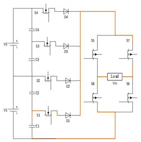
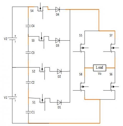
There are nine modes of operation of this inverter to achieve the required 9-level output Vo; the first four modes of operation give the positive levels of voltages, V/2, V, 3V/2, 2V and next four modes of operation give the negative levels of voltages, -V/2, -V, -3V/2, -2V and ninth mode ‘0V’is obtained by switching sequence mentioned in Table 1. All these modes of operation are presented in Figure 2, where current flow paths are highlighted in each mode of operation.
These eight operating modes along with the ‘0’V Operating mode is listed in table with respective output voltage levels.
Figure 1. Proposed symmetric 9-level inverter
Table 1. Switching sequence of the all modes of operations
|
Mode |
S1 |
S2 |
S3 |
S4 |
S5 |
S6 |
S7 |
S8 |
O/P Voltage |
|
I |
1 |
0 |
0 |
0 |
1 |
1 |
0 |
0 |
V/2 |
|
II |
0 |
1 |
0 |
0 |
1 |
1 |
0 |
0 |
V |
|
III |
0 |
0 |
1 |
0 |
1 |
1 |
0 |
0 |
(3/2)V |
|
IV |
0 |
0 |
0 |
1 |
1 |
1 |
0 |
0 |
2V |
|
V |
1 |
0 |
0 |
0 |
0 |
0 |
1 |
1 |
-V/2 |
|
VI |
0 |
1 |
0 |
0 |
0 |
0 |
1 |
1 |
-V |
|
VII |
0 |
0 |
1 |
0 |
0 |
0 |
1 |
1 |
-(3/2)V |
|
VIII |
0 |
0 |
0 |
1 |
0 |
0 |
1 |
1 |
-2V |
|
IX |
0 |
0 |
0 |
0 |
0 |
0 |
0 |
0 |
0 |
(a): Mode-I
(b): Mode-II
(c): Mode-III
(d): Mode-IV
(e): Mode-V
(f): Mode-VI
(g): Mode-VII
(h): Mode-VIII
Figure 2. Operating modes of proposed symmetric inverter
Harmonic reduction in the multi level inverters can be done by different modulation techniques, such as; Modulation with high frequency and modulation with low frequency. Modulation strategies with high switching frequency include; sine pulse modulation, stair cased modulation, digital pulse width modulation, phase shifted modulation etc., could remove harmonics of higher order in the inverter output [5]. But high-frequency modulation strategies will not remove harmonics of the lower order such as 3rd and 5th harmonics that are dominant in nature [9].
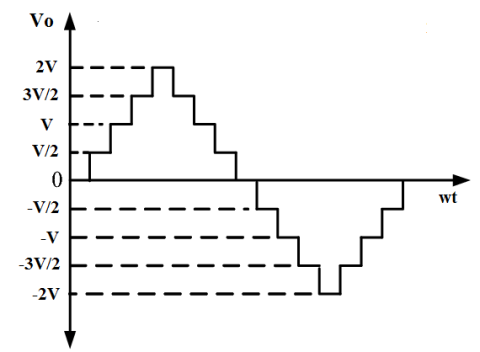
This condition can be solved by introducing low-frequency configurations such as modulation of the space vector pulse width and selective harmonic pulse width modulations [10]. This paper proposed a SHE-PWM to reduce the dominant harmonics of lower order and the switching losses in the proposed hybrid multilevel inverter [11]. A synthesized near sinusoidal output expected to obtain from the 9-level output is shown in Figure 3.
3.1 Selective Harmonic Elimination-PWM
For the above 9-level wave form the four switching angles $\theta_{1}, \theta_{2}, \theta_{3}, \theta_{4}$ need to be generated. By considering the charact eristics of the waveform, these switching angles are the function of Fourier series expression reported in ref. [18-21].
Figure 3. Proposed 9-Level synthesized near sinusoidal waveform
The generalized multi level inverter output is expressed by Fourier expansion:
$V_0=\sum\limits_{k=1}^{\infty }{\frac{4{{V}_{dc}}}{k\pi }}\left( \cos k{{\theta }_{1}}+\cos k{{\theta }_{2}}+......+\cos k{{\theta }_{n}} \right)*\sin k\omega t$ (1)
The necessary constraint the to be satisfied the switching angles from $\theta_{1}$ to $\theta_{n}$ is:
$0 \leq \theta_{1}<\theta_{2}<\theta_{3}<\theta_{4} \ldots \ldots \ldots<\theta_{n} \leq \frac{\pi}{2}$ (2)
The number of harmonics to be removed in the inverter output is 2Ns-1. The order of harmonics up to 6Ns-2 for K is odd, and up to 6Ns-1, for K is even, removed from the output waveform, where K is the order of harmonics. Thus with an inverter of nine levels with two DC outputs, the 5th, 7th, and 11th harmonics must be removed, and the transcendental equations to be satisfied are as follows.
$V_{1}=\cos \theta_{1}+\cos \theta_{2}+\cos \theta_{3}+\cos \theta_{4}=M I$
$V_{5}=\cos 5 \theta_{1}+\cos 5 \theta_{2}+\cos 5 \theta_{3}+\cos 5 \theta_{4}=0$
$V_{7}=\cos 7 \theta_{1}+\cos 7 \theta_{2}+\cos 7 \theta_{3}+\cos 7 \theta_{4}=0$
$V_{11}=\cos 11 \theta_{1}+\cos 11 \theta_{2}+\cos 11 \theta_{3}+\cos 11 \theta_{4}=0$ (3)
For optimum switching angles, modulation index (MI) is;
$M I=\frac{V_{1}}{\frac{16 V_{d c}}{\pi}}$ for $0 \leq M I \leq 1$ (4)
The optimization strategy for the proposed nine-level MLI is taken into account in order to solve non-linear transcendental equations [18, 19]. The significant step of any optimization technique is to create a fitness function, which relates to the variables to be evaluated. The main objectives are,
The magnitude of the harmonics depends on the angles of switching. To accomplish the above objectives the fitness function (FF) takes the form as follows:
$F F=100 * \frac{\left(V_{1 d}-V_{1}\right)^{4}}{V_{1 d}^{4}}+\left(\frac{50}{V_{1}}\right)^{2} *\left(\frac{V_{5}^{2}}{5}+\frac{V_{7}^{2}}{7}+\frac{V_{11}^{2}}{11}\right)$ (5)
3.2 ANT Optimization for SHE-PWM
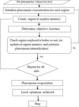
Ant optimization (ACO) is the first to investigate an optimal path in an evolutionary-based on ant's behavior to find a path between their colony and food source [22, 23]. Figure 4 shows the step by step procedure to be followed to implement the Ant colony optimization algorithm. This algorithm is implemented in MATLAB for the solution of transcendental equations, which provides optimized switching angles for the proposed inverter.
Figure 4. A flow chart for Ant colony optimization
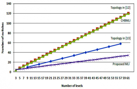
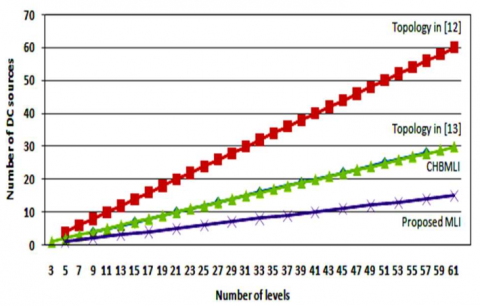
A symmetric 9-level inverter is implemented using MATLAB SIMULINK software. To generate 4-steps in each half cycle of output, 4-sources are required. These 4-sources are derived from 2-dc sources using split capacitors. This topology uses a smaller number of power switches compared to other 9-level topologies. The number of power switches and dc sources required to build this 9-level inverter is compared with other topologies and presented in Figure 5 and in Figure 6. Figure 5 shows the variance in the number of switches needed to model the proposed inverter for different output voltage rates.
Figure 5. Comparison for number of active switches
The variation in the number of dc sources needed to model the proposed inverter for different output voltage levels is shown in the Figure 6.
Figure 6. Comparison for number of DC sources
The transcendental equations shown in Eq. (3) is solved for satisfying the fitness in Eq. (5), the switching angles of the proposed inverter is evaluated and tabulated in Table 2.
Table 2. Switching angles obtained from the Ant colony optimization algorithm
|
Algorithm |
MI |
Optimized Switching Angles (degrees) |
THD % |
|||
|
θ1 |
θ2 |
θ3 |
θ4 |
|
||
|
ANT |
9.46 |
19.65 |
36.92 |
59.45 |
5.60 |
|
The switching angles were applied to the proposed symmetric inverter and simulated for output voltage and current. Figure 7 shows the 9-level output voltage of the proposed inverter and Figure 8 shows the load current waveform for R-L load.
Figure 7. 9-Level load waveform of proposed inverter
Figure 8. Load current waveform of proposed inverter
The THD of the output voltage is computed by analysing the load voltage waveform with Fourier analysis for maximum harmonic frequency. The magnitude of THD obtained for the output voltage is 5.6% and is satisfactory as per IEEE-519 standards. The graph of THD anaylis is shown in Figure 9.
Figure 9. THD analysis of proposed inverter
This paper presented a novel symmetric inverter with reduced switches for a nine-level inverter using MATLAB® SIMULINK. To optimize the switching angles of the multi-level inverter, a low frequency switching modulation called SHE-PWM is used to reduce switching losses and THD. An optimization technique, Ant Colony optimization, is implemented and obtained the optimized angles for the semiconductor switches of the proposed circuit. In addition, less THD is achieved by adopting the Ant Colony Optimization technique. The output voltage obtained is approximately a sinusoidal wave. The inverter output voltage THD calculation indicates the THD is 5.60%. Therefore, the suggested inverter is compliant with different single-phase applications.
[1] Tolbert, L.M., Fang, Z.P., Habetler, T.G. (1999). Multilevel converters for large electric drives. IEEE Transactions on Industry Applications, 35(1): 36-44. https://doi.org/10.1109/28.740843
[2] Villanueva, E., Correa, P., Rodriguez, J., Pacas, M. (2009). Control of a single-phase cascaded H-Bridge multilevel inverter for grid-connected photovoltaic systems. IEEE Transactions on Industrial Electronics, 56(11): 4399-4406. https://doi.org/10.1109/TIE.2009.2029579
[3] van Wyk, J.D., Lee, F.C. (2013). On a future for power electronics. IEEE Journal of Emerging and Selected Topics in Power Electronics, 1(2): 59-72. https://doi.org/10.1109/JESTPE.2013.2271499
[4] Holtz, J. (1992). Pulsewidth modulation-a survey. IEEE Transactions on Industrial Electronics, 39(5): 410-420. https://doi.org/10.1109/41.161472
[5] Du, Z., Tolbert, L.M., Ozpineci, B., Chiasson, J.N. (2009). Fundamental frequency switching strategies of a seven-level hybrid cascaded H-bridge multilevel inverter. IEEE Transactions on Power Electronics, 24(1): 25-33. https://doi.org/10.1109/TPEL.2008.2006678
[6] Nazarpour, D., Sabahi, M., Alishah, R.S., Hosseini, S.H. (2014). New hybrid structure for multilevel inverter with fewer number of components for high-voltage levels. IET Power Electron., 7(1): 96-104. https://doi.org/10.1049/iet-pel.2013.0156
[7] Liu, Y., Hong, H., Huang, A.Q. (2009). Real-time calculation of switching angles minimizing THD for multilevel inverters with step modulation. IEEE Transactions on Industrial Electronics, 56(2): 285-293. https://doi.org/10.1109/TIE.2008.918461
[8] Gupta, K.K., Ranjan, A., Bhatnagar, P., Sahu, L.K., Jain, S. (2016). Multilevel inverter topologies with reduced device count: A review. IEEE Transactions on Power Electronics, 31(1): 135-151. https://doi.org/10.1109/TPEL.2015.2405012
[9] Massoud, A.M., Finney, S.J., Cruden, A., Williams, B.W. (2007). Mapped phase-shifted space vector modulation for multilevel voltage source inverters. IET Electr. Power Appl., 1(4): 622-636. https://doi.org/10.1049/iet-epa:20060273
[10] Kouzou, A. (2015). Selective harmonics elimination PWM applied to multilevel four-legs DC/AC converter based on particle swarm optimization. 2015 4th International Conference on Electric Power and Energy Conversion Systems (EPECS), pp. 1-7. https://doi.org/10.1109/EPECS.2015.7368501
[11] Kumar, N.V., Chinnaiyan, V.K., Pradish, M., Divekar, M.S. (2016). Selective harmonic elimination: An comparative analysis for seven level inverter. 2016 IEEE Students’ Technology Symposium (TechSym), pp. 157-162. https://doi.org/10.1109/TechSym.2016.7872674
[12] Hota, A., Jain, S., Agarwal, V. (2017). An optimized three-phase multilevel inverter topology with separate level and phase sequence generation part. IEEE Transactions on Power Electronics, 32(10): 7414-7418. https://doi.org/10.1109/TPEL.2017.2688394
[13] Lee, S.S., Sidorov, M., Lim, C.S., Idris, N.R.N., Heng, Y.E. (2018). Hybrid cascaded multilevel inverter (HCMLI) with improved symmetrical 4-level submodule. IEEE Transactions on Power Electronics, 33(2): 932-935. https://doi.org/10.1109/TPEL.2017.2726087
[14] Rajesh, B., Manjesh. (206). Comparison of harmonics and THD suppression with three and 5 level multilevel inverter-cascaded H-bridge.1 2016 International Conference on Circuit, Power and Computing Technologies (ICCPCT), pp. 1-6. https://doi.org/10.1109/ICCPCT.2016.7530116
[15] Gupta, C., Varshney, A., Verma, N., Shukla, S. (2015). THD analysis of eleven level cascaded h-bridge multilevel inverter with different types of load using in drives applications. 2015 Second International Conference on Advances in Computing and Communication Engineering, pp. 355-359. https://doi.org/10.1109/ICACCE.2015.61
[16] Sabari, A., Omar, R., Sulaiman, M., Rasheed, M. (2014). Optimization and non-optimization of H-bridge cascaded multilevel inverter. 3rd IET International Conference on Clean Energy and Technology (CEAT) 2014, pp. 1-6. https://doi.org/10.1049/cp.2014.1497
[17] Ray, R.N., Chatterjee, D., Goswami, S.K. (2010). A PSO based optimal switching technique for voltage harmonic reduction of multilevel inverter. Expert System with Application., 37: 7796-7801. https://doi.org/10.1016/j.eswa.2010.04.060
[18] Patil, S.D., Kadwane, S.G. (2017). Application of optimization technique in SHE controlled multilevel inverter. 2017 International Conference on Energy, Communication, Data Analytics and Soft Computing (ICECDS), pp. 26-30. https://doi.org/10.1109/ICECDS.2017.8390050
[19] Abu-Rub, H., Holtz, J., Rodriguez, J., Baoming, G. (2010). Medium-voltage multilevel converters—state of the art, challenges, and requirements in industrial applications. IEEE Transactions on Industrial Electronics, 57(8): 2581-2596. https://doi.org/10.1109/TIE.2010.2043039
[20] Ahmed, M., Sheir, A., Orabi, M. (2017). Real-time solution and implementation of selective harmonic elimination of seven-level multilevel inverter. IEEE Journal of Emerging and Selected Topics in Power Electronics, 5(4): 1700-1709. https://doi.org/10.1109/JESTPE.2017.2746760
[21] Yu, Y., Zhang, P., Song, Z., Chai, F. (2018). Composite differential evolution algorithm for SHM with low carrier ratio. IET Power Electronics, 11(6): 1101-1109. https://doi.org/10.1049/iet-pel.2017.0588
[22] Babaei, M., Rastegar, H. (2017). Selective harmonic elimination PWM using ant colony optimization. 2017 Iranian Conference on Electrical Engineering (ICEE), pp. 1054-1059. https://doi.org/10.1109/IranianCEE.2017.7985195
[23] Patil, S.D., Kadwane, S.G., Gawande, S.P. (2016). Ant Colony Optimization applied to selective harmonic elimination in Multilevel inverters. 2016 2nd International Conference on Applied and Theoretical Computing and Communication Technology (iCATccT), pp. 637-640. https://doi.org/10.1109/ICATCCT.2016.7912078