Rachid Maouedj* | Ahmed Youcef
© 2020 IIETA. This article is published by IIETA and is licensed under the CC BY 4.0 license (http://creativecommons.org/licenses/by/4.0/).
OPEN ACCESS
Details on the hydrothermal behavior of airflows in a horizontal channel heat exchanger are provided in this paper. The exchanger is equipped with twisted fins under a staggered arrangement. The investigations are achieved with the CFD (Computational Fluid Dynamics) method. Turbulent flows are considered with a Reynolds number (Re) in the range [1.2×10⁴-3.6×10⁴]. The SST k-ω model is selected to describe the turbulent flows. The flow patterns, thermal fields, Nusselt number (Nu) and the skin friction factor (f) are determined for various flow rates. From the calculations, the suggested design of fins allowed a significant improvement in the heat exchange within the device.
mathematical modelling, computational fluid dynamics, turbulent flows, forced convection, solar channel air- heat exchanger, twisted fins
The solar collectors are generally used in the space heating, solar cooling, solar greenhouses, food refrigeration machines, and more particularly in the field of drying of food products. This requires an effective structure for high performance.
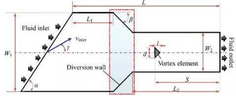
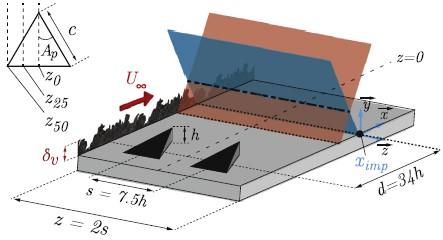
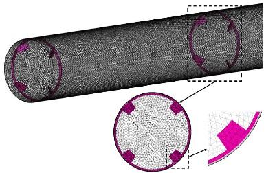
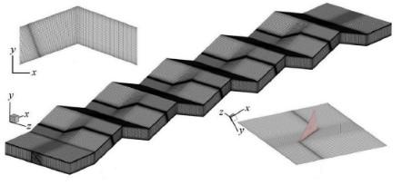
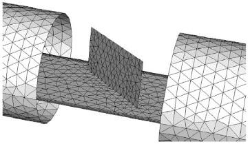
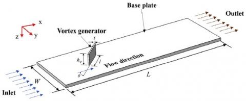
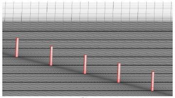
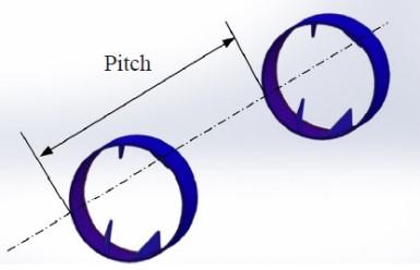
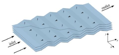
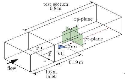
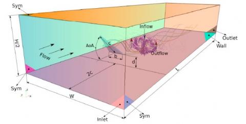
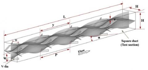
To obtain the high-energy efficiency, it is necessary to implant obstacles ‘baffles and fins’ in the airflow between the insulator and the absorber. The inserted obstacles create turbulence and lengthen the path of fluid through, which enhances the thermal exchange. Therefore, many researchers focused in their studies on the impact of various types of vortex generators (VGs) inside duct heat exchangers, (for example, see Figure 1). Ji et al. [1] reported a CFD (computational fluid dynamics) based study of recirculation flows in a variable cross-section channel with a triangular-prismatic VG. Grébert et al. [2] used large-eddy simulations (LES) to investigate a three-dimensional turbulent fluid domain with microramp-type vortex-generators (mVGs). Sun et al. [3] analyzed the overall performance of circular-form tubes in heat exchangers with multiple rectangular-winglet section VGs. Promvonge et al. [4] experimentally used both twisted-tape and winglet-VGs to enhance the thermal performance of a duct of square section. Luo et al. [5] combined wavy-type fins and VGs to improve the hydrothermal aspects of heat exchangers. da Silva et al. [6] explored two different types of longitudinal VGs, rectangular-winglet and delta-winglet, to augment the heat transfer in a circular-tube solar-collector. Kashyap et al. [7] considered a rectangular VG to increase the rate of heat transfer from a horizontal-section plate to fluid. Jiao et al. [8] studied and analyzed the characteristics of heat transfer in a rectangular-shape channel with different arrangement miniature-cuboid VGs.
(a) Fluid domain with variable cross-section [1]
(b) Fluid configuration with mVGs [2]
(c) Tube with multiple rectangular winglet VGs [3]
(d) Duct with twisted-tape and winglet VGs [4]
(e) Zig-zag channel with VGs [5]
(f) Tube with rectangular-winglet VGs [6]
(g) Horizontal plate with rectangular VGs [7]
(h) Rectangular channel with miniature cuboid VGs [8]
(i) Circular tube with delta winglet VGs [9]
(j) Wavy fin with delta winglet VGs [10]
(k) Rectangular channel with angled ribs [11]
(l) Fin-and-tube heat exchanger with curved VGs [12]
(m) Channel with a tetrahedral, full-body VG [13]
(n) Radiator with delta-wing VGs [14]
(o) Duct with quadruple V-finned twisted tapes [15]
(p) Tube with inclined rectangular ribs [16]
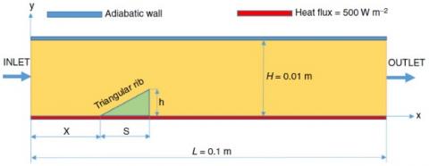
(q) Channel with a triangular rib [17]
Figure 1. Various flow configurations with different types of vortex generators (VGs)
Zhai et al. [9] conducted a heat transfer experiment to calculate the Nusselt number, friction factor and thermal performance through a circular-tube with delta winglet VGs of various situations. Luo et al. [10] proposed a new combination of a different corrugation-angle wavy-type fin and various attack-angle VGs to enhance the overall performance of heat exchangers. Sohankar [11] augmented the heat transfer in a rectangular-geometry channel by using a vee-type VG (i.e., two inclined ribs). Lu and Zhai [12] conducted CFD simulations to highlight the hydrothermal behavior of fin surface-attached curved VGs in heat exchangers. Henze et al. [13] experimentally analyzed the speed field as well as the heat transfer inside a channel with one tetrahedral full-body type VG. Garelli et al. [14] used a 3D simulation to examine the efficiency of delta-wing VGs for improving the heat transfer in radiators. Using an experimental approach, Promvonge [15] investigated the thermal enhancement inside a duct of square form with twisted tape-attached V-fins. Pourfattah et al. [16] used a numerical study to investigate the turbulent heat-transfer and flow characteristics in a tube with various attack inclined-rectangular type ribs. Ekiciler [17] used a new hybrid nanofluid of TiO2-Cu/EG and exploded a lower-placed triangular-type rib with various heights, positions and lengths, in order to improve the turbulent forced-convection flow in a 2D duct. Al-Asadi et al. [18] explored a novel geometry of VGs to reinforce the 3D conjugate heat transfer of a laminar micro-channel flow by using a CFD technique. Al-Asadi et al. [19] also reported another simulation to examine the impact of pin fin perforations under laminar heat transfer flow in heat sinks. Aravind and Deepu [20] enhanced the mass transfer in high-velocity fluid flows by combined lateral sweep VGs and dimple surfaces. Awais and Bhuiyan [21] performed a parametric analysis of effects of different arrangement and form tubes with various configuration, row number and attack VGs on the thermal and flow aspects of compact finned-tube type heat-exchangers. Chomdee and Kiatsiriroat [22] aimed to experimentally study the hydrothermal performance of staggered electronic modules with upstream delta-winglet VGs. Ramanathan et al. [23] summarized the flow and heat transfer performance of a various attack VG in a sudden expansion channel for different flow rates. Xiao et al. [24] included inclined trapezoidal VGs to optimize the flow and heat transfer aspects of the solar-duct air-heater. Samadifar and Toghraie [25] examined the effect of various VG situations (wavy, intended, wishbone, angular-rectangular, rectangular-trapezius and simple rectangular) on the efficiency of a triangular-channel heat-exchangers. Wang et al. [26] used both particle-image-velocimetry experiment and numerical simulation to analysis the laminar thermal efficiency of a circular-shaped tube with various slice height, spacing length and central angle longitudinal VGs. Zdanski et al. [27] verified the impact of delta-winglet deflectors on the pressure loss and heat transfer aspects for in-line arrangement in the tube bank. Demartini et al. [28] reported the distribution of speed and pressure-coefficient profiles in various axial stations from a rectangular-channel heat-exchanger by using both numerical and experimental approaches.
Here, we are interested in the determination of the hydrothermal behavior of air in a solar rectangular-channel heat-exchanger. Twisted fins are inserted to enhance the overall performances. The study is conducted numerically for Re in the range [1.2×10⁴-3.6×10⁴].
2.1 Case study
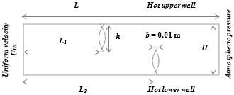
The inspected physical case is illustrated in Figure 2. It concerns a duct with two twisted transverse fins. The selected geometrical parameters are those on the experiments conducted by Demartini et al. [28], where the duct length (L), its height (H), and its hydraulic-diameter (Dh) are 0.554, 0.146, and 0.167 m, respectively. Under the steady-state condition and a 2D assumption, the turbulent airflows are considered. The 1st fin is inserted at L1 = 0.218 m from the intake station, while the 2nd fin is placed at 0.174 m from the exit station (i.e., at L2 = 0.37 m from the inlet section). These fins are inserted under a staggered arrangement (on the opposite walls of the duct). The distance of separation between the fin-tip and the duct-wall (h) is 0.08 m.
Figure 2. Computational domain
2.2 Governing equations
The following assumptions are selected in the computation:
From these assumptions, the governing fluid-flow equations are given as [29]:
Continuity equation:
$\nabla \vec{V}=0$ (1)
Momentum equation:
$\rho_{f}(\vec{V} . \nabla \vec{V})=-\nabla P+\mu_{f} \nabla^{2} \vec{V}$ (2)
Energy equation:
$\rho_{f} C_{p f}(\vec{V} . \nabla T)=\lambda_{f} \nabla^{2} T$ (3)
k turbulent kinetic energy equation:
$\frac{\partial}{\partial x_{i}}\left(\rho \cdot k \cdot u_{i}\right)=\frac{\partial}{\partial x_{j}}\left(\Gamma_{k} \frac{\partial k}{\partial x_{j}}\right)+G_{k}-Y_{k}+S_{k}$ (4)
ω dissipation of turbulent kinetic energy equation:
$\frac{\partial}{\partial x_{i}}\left(\rho \cdot \omega \cdot u_{i}\right)=\frac{\partial}{\partial x_{j}}\left(\Gamma_{\omega} \frac{\partial \omega}{\partial x_{j}}\right)+G_{\omega}-Y_{\omega}+D_{\omega}+S_{\omega}$ (5)
2.3 Characteristic quantities of flow and heat transfer
Reynolds number:
$\mathrm{Re}=\frac{\rho_{f} D_{h} u_{m}}{\mu_{f}}$ (6)
The friction factor:
$f=\frac{2 \cdot \tau_{w}}{\rho \cdot u_{m}^{2}}$ (7)
Local Nusselt number:
$N u_{x}=\frac{h_{x} \cdot D_{h}}{\lambda_{f}}$ (8)
Average Nusselt:
$\overline{N u}=\frac{1}{L} \int N u_{x} \partial x$ (9)
3.1 Boundary conditions
The flow and thermal boundary conditions are based on the experiments of Demartini et al. [28] and Nasiruddin and Siddiqui [29], respectively. A uniform velocity (u = Uin) and a temperature Tin= 300 K are set at the intake station (x = 0), while an atmospheric pressure (Patm) is applied at the outlet (x = L). The no-slip condition and a fixed temperature Tw = 375 K are applied at the walls of the exchanger (i.e., u = v = 0).
3.2 Mesh characteristics
A structured mesh with quadrilateral elements type was generated. A total number of grid elements of 250 × 100 to model fluid flow in this problem as axial and radial directions, respectively, was used. This mesh was refined in the regions with high gradients of the velocity and temperature occur, exactly at the interface fluid-wall and near the fins. To confirm the negligible effect of the mesh, a series of tests for non-uniform meshes was conducted. The mesh density was increased until the results did not change by more than 1.25%.
3.3 CFD technique
The governing equations were solved numerically by the finite volume technique [30]. The SIMPLE algorithm [30] was employed to ensure the velocity-pressure coupling. The Quick numerical scheme (Quadratic Upwind Interpolation for Convective Kinetics) [31] was used for the discretization of the diffusion terms, while, and the second order scheme [30] was employed for the pressure terms. The residual target of $10^{-6}$ was used as a convergence criterion for all variables (temperature, pressure, velocity, etc.).
4.1 Comparison against the experimental data
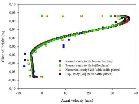
To verify the reliability of the predicted findings with the software FLUENT, the validation of our computations was made against the experimental values of Demartini et al. [28]. These authors studied a similar problem for the circulation of air in a channel with transverse plane obstacles. At Re = 8.73×10⁴, the results of the axial velocity are presented in Figure 3. As exhibited, the validation proves the accuracy of our predicted results.
Figure 3. Validation of the results of axial velocity
4.2 Hydrodynamic aspect
We focus here on the impact of twisted fins on the hydrothermal characteristics of the solar collector at high Re. Details on the streamlines, velocity distribution, and the friction factors are presented in the first section, whereas the thermal fields and the values of the Nusselt numbers are provided in the second part. The forced convection of turbulent airflows inside a baffled collector is characterized by flow instabilities, where their knowledge and understanding are highly required.
4.2.1 Velocity field and contour of streamlines
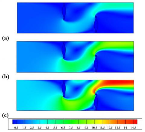
The flow behavior within the baffled duct at Re = 1.2×10⁴-3.6×10⁴ is highlighted in Figures 4 and 5. As observed from the plots of the dynamic fields, the flow is completely disturbed at high velocity of the air when reaching the fins, where three major areas of perturbation may be distinguished. In the 1st area just upstream of the two fins, the fluid flow changes its direction and recirculation loops are formed. In the 2nd area between the tip of each fin and the opposing wall of the duct, high flow velocities of the order of 15 times of Uin are observed, at Re = 3.6×10⁴. The augmentation of velocity in this area is due to the reduction of the passage of the main flow. In the 3rd area just downstream of each fin, recirculating cells with low velocities are observed.
Figure 4. Flow patterns in the baffled duct, at Re = (a) 1.2×10⁴, (b) 2.4×10⁴ and (c) 3.6×10⁴
Figure 5. Distribution of mean-velocity in the finned duct, at Re = (a) 1.2×10⁴, (b) 2.4×10⁴ and (c) 3.6×10⁴
4.2.2 Axial velocity
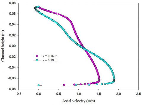
The axial velocity is plotted at various positions in the duct (Figures 6-9). Figure 6 illustrates the u-profiles upstream of the 1st obstacle at x = 0.16 and 0.19 m. The u-velocity is decrease in the upper section of the duct when approaching the 1st obstacle, while it increases elsewhere.
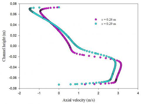
The profiles of u-velocity between the two baffles at x = 0.26 and 0.29 m from the inlet are presented in Figure 7. The negative values of u-velocity in the upper part of the duct mean the presence of a recirculation cell downstream of the 1st obstacle. In addition, relatively high velocities of the order of 3 times over Uin are observed near the baffle tip.
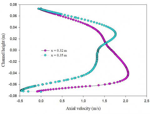
Two other positions x = 0.32 and 0.35 m, which correspond to the region just upstream of the 2nd obstacle, were selected for the presentation of u-profiles in Figure 8. When approaching the 2nd obstacle, the intensity of the flow is reduced in the lower part of the duct, while it is accelerated elsewhere. These vortices that are characterized by negative values greatly augment the flow resistance.
Figure 6. Variation of u-velocity upstream the 1st baffle, at Re = 1.2 ×10⁴
Figure 7. Variation of u-velocity downstream of the 1st baffle, Re = 1.2 ×10⁴
Figure 8. Variation of u-velocity upstream of the 2nd baffle, at Re = 1.2 ×10⁴
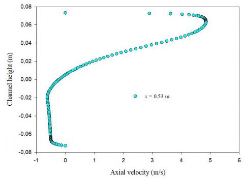
The u-profiles are also depicted near the duct exit (Figure 9). The velocity is approximately equal to 4.85 m/s just before the outlet (at x = 0.53 m), which is higher than uin by about 4.62 times.
Figure 9. u-velocity after the 2nd baffle, at Re = 1.2×10⁴
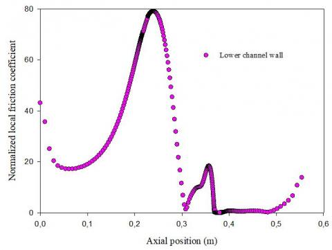
4.2.3 Normalized local friction coefficient (Cf/f0)
The Cf/f0 variation along with the bottom wall are depicted in Figure 10a. In the region between 0.1 and 0.3 m, the orientation of the flow with high velocities towards the lower wall of the duct, which is caused by the 1st obstacle, yielded an augmentation in Cf/f0 values. However, negligible values of Cf/f0 are observed at the duct exit due to the variations in the flow direction that is generated by the 2nd obstacle.
(a) Lower channel wall
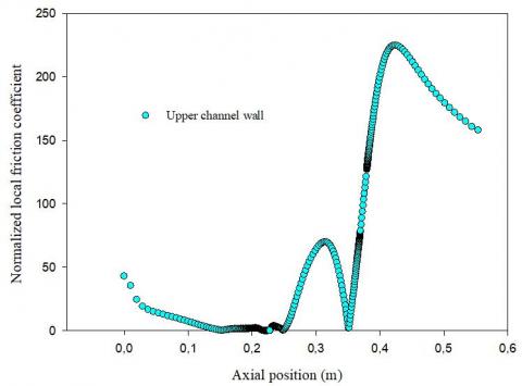
(b) Upper channel wall
Figure 10. Values of Cf/f0 on the walls of the exchanger, at Re = Re = 1.2 ×10⁴
The changes in Cf/f0 values on the upper wall of the exchanger are also highlighted (Figure 10b). Very low values of Cf/f0 are located in the unbaffled region of the exchanger, i.e., in the upstream region of the 1st obstacle. However, the presence of recirculation loops in the area between the two-baffles yielded an increase in Cf/f0 values.
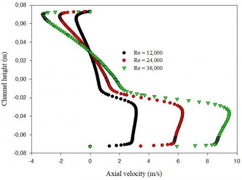
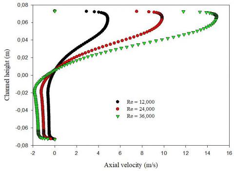
4.2.4 Influence of Re on u-velocity
Various positions were selected (x = 0.26 and x = 0.53 m) to examine the effect of Re on the u-velocity, Figures 11 (a-and-b). For Re varying from 1.2×10⁴ to 3.6×10⁴ an increase in the acceleration of the flow and the size of the recirculation cells is observed.
(a) at x = 0.26 m
(b) at x = 0.53 m
Figure 11. Changes in u-velocity downstream of the (a) 1st and (b) the 2nd fins: Impact of Reynolds number
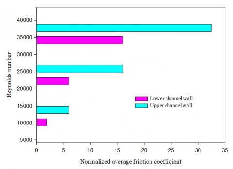
Figure 12. Normalized average friction coefficient vs. Re
4.2.5 Impact of Re on the normalized mean friction (Cf/f0)
The change in the normalized average friction factor on the upper and lower walls of the exchanger vs. Reynolds number is illustrated in Figure 12. A significant increase in Cf is reached with the rise of Re due to the augmentation of the pressure drop that is resulted by the increase of the flow resistance.
4.3 Thermal exchange aspect
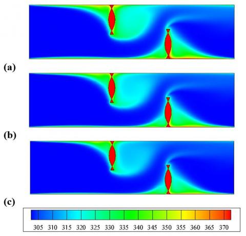
4.3.1 Thermal field
The temperature distribution within the exchanger is presented in Figure 13 at Re = 5,000. A decrease in the temperature is observed in the space between the top of each obstacle and the duct walls. Furthermore, recirculation loops with relatively high temperatures are located in the downstream region of each baffle. The heat transfer is accelerated just after the 2nd baffle and the most significant amount of the temperature is reached on the lower wall of the exchanger.
Figure 13. Distribution of the thermal field in the duct at Re = (a) 1.2×10⁴, (b) 2.4×10⁴ and (c) 3.6×10⁴
4.3.2 Temperature profiles in specific regions
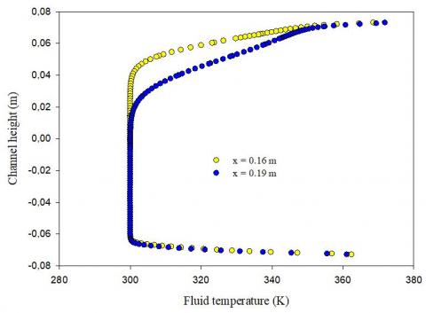
The profiles of the total temperature are given in Figures 14-17 in various positions of the exchanger. Figure 14 depicts the result of the total temperature at x = 0.16 and 0.19 m, i.e., upstream of the 1st obstacle. A considerable augmentation in the temperature is observed at the upper half of the exchanger due to the presence of the 1st baffle, while low values of T are remarked at the other half.
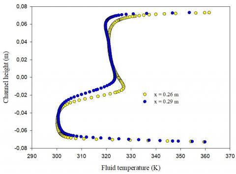
In the region between the two baffles and precisely at x = 0.26 and 0.29 m, Figure 15 indicates high amounts of the temperature in the upper part of the exchanger, while low T values are present in the lower part. It is noted also that the closer region to the baffle is the most heated.
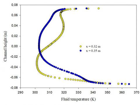
Values of T upstream of the 2nd baffle are also provided for two locations (x = 0.32 and 0.35 m) and presented in Figure 16. When the flow approaches the 2nd VG, the temperature is augmented in the lower part of the exchanger, while it is reduced in the other part compared with the previous two locations.
Figure 14. Variation of the fluid temperature upstream of the 1st baffle, at Re = 1.2 ×10⁴
Figure 15. Changes in the fluid temperature downstream of the 1st baffle, at Re = 1.2 ×10⁴
Figure 16. Changes in the fluid temperature upstream of the 2nd baffle, at Re = 1.2 ×10⁴
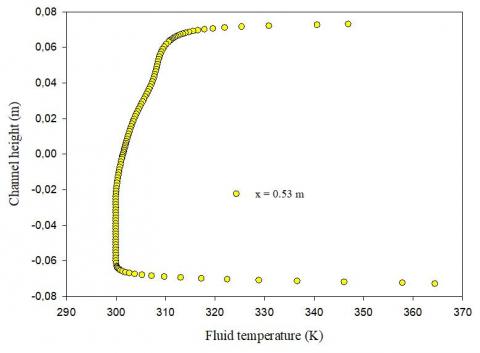
The curves of the total temperature given in Figure 17 are plotted at x = 0.53 m, i.e., near the duct exit. This section is characterized by a considerable decrease of the temperature due to the absence of baffles.
Figure 17. Variation of the fluid temperature after the 2nd baffle near the duct exit, at Re = 1.2 ×10⁴
4.3.3 Impact of Re on the thermal field
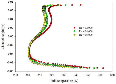
The thermal fields vs. Re are given in Figure 18 for an axial position corresponding to the upstream region of the 2nd obstacle, precisely at x = 0.32 m, respectively. As clearly highlighted, a significant reduction in the temperature is obtained with the rise of Re.
Figure 18. Distribution of the fluid temperature upstream of the 2nd fin: Impact of Reynolds number
4.3.4 Nusselt numbers
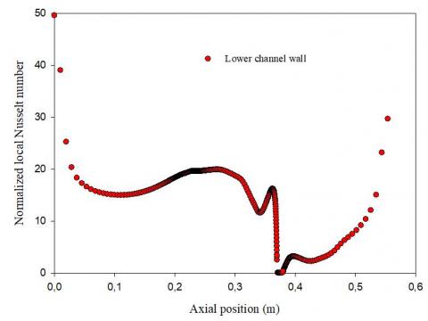
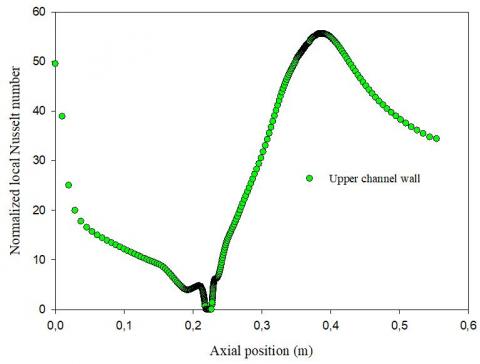
The present arrangement of baffles is similar to a sudden expansion, which promotes the formation of vortices in the vertical axe relative to the plane of the main fluid flow. Figure 19 presents the variation of the normalized local Nusselt number (Nux/Nu0) along with the lower and upper walls. As exhibited, the minimum value of heat transfer rate is located at the base of the obstacles, while its highest amount is observed on the upper sides of the VGs.
The augmentation of Reynolds number, i.e., the acceleration of flows, yielded an augmentation in the size of the recirculation loops. These structures are characterized by a great disturbance of the fluid particle, which promotes the mixing and enhances the heat transfer rates.
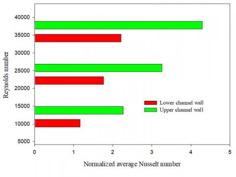
For Re values between 1.2 × 10⁴ and 3.6 × 10⁴, a direct relationship is observed between the augmentation in the average Nu/Nu0 and the rise of Re, where the thermal exchange rate reaches its highest value on the upped wall (Figure 20).
(a) Lower channel wall
(b) Upper channel wall
Figure 19. Values of the Nux/Nu0 on the walls of the exchanger, at Re = 1.2 ×10⁴
Figure 20. Normalized mean Nu along with the duct vs. Re
The hydrothermal behavior of turbulent airflows through a rectangular-channel air-heat exchanger was examined numerically. Twisted fins were inserted on the upper and lower walls of the exchanger under a staggered arrangement to enhance the overall performances.
The predicted results revealed complex structures of the flow with the presence of VGs, where strong recirculation loops are formed in the corners of each fin. The flow is deflected towards the upper and lower walls of the duct with high velocities.
A great impact of the flow behavior on the thermal details was remarked, where the low thermal exchange occurred in the regions of vortices. Also, the distributions of the Nusselt number changed with the fin design.
In addition, the obtained findings illustrated an inverse relationship between the augmentation in the flow rate and the total decrease in the temperature. The increased Re yielded an increase in the gradient of the temperature at the hot wall.
|
b |
Thickness of the fixation base of the fin, m |
||
|
Cp |
Specific heat, J kg-1 K-1 |
||
|
Dh |
Hydraulic diameter of the exchanger, m |
||
|
f |
Average coefficient of friction |
||
|
f0 |
Factor of friction for present smooth exchanger |
||
|
H |
Height of exchanger, m |
||
|
h |
Height of twisted fin, m |
||
|
hx |
Convective heat exchange coefficient, W.m-2 K-1 |
||
|
k |
Kinetic energy of turbulence, m2 s-2 |
||
|
L |
Length of exchanger, m |
||
|
L1 |
Inlet-1st fin space, m |
||
|
L2 |
Inlet-2nd fin space, m |
||
|
Nu |
Average Nusselt number of the finned exchanger |
||
|
Nu0 |
Average Nu number for present smooth exchanger |
||
|
P |
Pressure, Pa |
||
|
Patm |
Atmospheric pressure, Pa |
||
|
Re |
Number of Reynolds |
||
|
T |
Temperature, K |
||
|
Tin |
Inlet fluid temperature, K |
||
|
Tw |
Wall temperature, K |
||
|
u |
X-velocity, m s-1 |
||
|
Uin |
Intake velocity, m s-1 |
||
|
um |
Average velocity of the section, m s-1 |
||
|
v |
Y-velocity, m s-1 |
||
|
Greeks symbols |
|||
|
λ |
Thermal-conductivity, W m-1 K-1 |
||
|
μ |
Dynamic viscosity, kg m-1 s-1 |
||
|
ρ |
Density, kg m-3 |
||
|
τw |
Wall-shear-stress, Pa |
||
|
Subscript |
|||
|
atm |
Atmosphere |
||
|
f |
Fluid |
||
|
in |
Intake |
||
|
w |
Wall |
||
|
x |
Local |
||
[1] Ji, J., Gao, R., Chen, W., Liu, B., Chen, Q. (2020). Analysis of vortex flow in fluid domain with variable cross-section and design of a new vortex generator. International Communications in Heat and Mass Transfer, 116: 104695. https://doi.org/10.1016/j.icheatmasstransfer.2020.104695
[2] Grébert, A., Bodart, J., Jamme, S., Joly, L. (2018). Simulations of shock wave/turbulent boundary layer interaction with upstream micro vortex generators. International Journal of Heat and Fluid Flow, 72: 73-85. https://doi.org/10.1016/j.ijheatfluidflow.2018.05.001
[3] Sun, Z., Zhang, K., Li, W., Chen, Q., Zheng, N. (2020). Investigations of the turbulent thermal-hydraulic performance in circular heat exchanger tubes with multiple rectangular winglet vortex generators. Applied Thermal Engineering, 168: 114838. https://doi.org/10.1016/j.applthermaleng.2019.114838
[4] Promvonge, P., Suwannapan, S., Pimsarn, M., Thianpong, C. (2014). Experimental study on heat transfer in square duct with combined twisted-tape and winglet vortex generators. International Communications in Heat and Mass Transfer, 59: 158-165. http://dx.doi.org/10.1016/j.icheatmasstransfer.2014.10.005
[5] Luo, C., Song, K., Tagawa, T., Wu, X., Wang, L. (2020). Thermal performance of a zig-zag channel formed by two wavy fins mounted with vortex generators. International Journal of Thermal Sciences, 153: 106361. https://doi.org/10.1016/j.ijthermalsci.2020.106361
[6] da Silva, F.A.S., Dezan, D.J., Pantaleão, A.V., Salviano, L.O. (2019). Longitudinal vortex generator applied to heat transfer enhancement of a flat plate solar water heater. Applied Thermal Engineering, 158: 113790. https://doi.org/10.1016/j.applthermaleng.2019.113790
[7] Kashyap, U., Das, K., Debnath, B.K. (2018). Effect of surface modification of a rectangular vortex generator on heat transfer rate from a surface to fluid. International Journal of Thermal Sciences, 127: 61-78. https://doi.org/10.1016/j.ijthermalsci.2018.01.004
[8] Jiao, Y., Wang, J., Liu, X. (2020). Heat transfer and flow characteristics in a rectangular channel with miniature cuboid vortex generators in various arrangement. International Journal of Thermal Sciences, 153: 106335. https://doi.org/10.1016/j.ijthermalsci.2020.106335
[9] Zhai, C., Islam, M.D., Alam, M.M., Simmons, R., Barsoum, I. (2019). Parametric study of major factors affecting heat transfer enhancement in a circular tube with vortex generator pairs. Applied Thermal Engineering, 153: 330-340. https://doi.org/10.1016/j.applthermaleng.2019.03.018
[10] Luo, C., Wu, S., Song, K., Hua, L., Wang, L. (2019). Thermo-hydraulic performance optimization of wavy fin heat exchanger by combining delta winglet vortex generators. Applied Thermal Engineering, 163: 114343. https://doi.org/10.1016/j.applthermaleng.2019.114343
[11] Sohankar, A. (2007). Heat transfer augmentation in a rectangular channel with a vee-shaped vortex generator. International Journal of Heat and Fluid Flow, 28: 306-317. https://doi.org/10.1016/j.ijheatfluidflow.2006.03.002
[12] Lu, G., Zhai, X. (2019). Effects of curved vortex generators on the air-side performance of fin-andtube heat exchangers. International Journal of Thermal Sciences, 136: 509-518. https://doi.org/10.1016/j.ijthermalsci.2018.11.009
[13] Henze, M., von Wolfersdorf, J., Weigand, B., Dietz, C.F., Neumann, S.O. (2011). Flow and heat transfer characteristics behind vortex generators - a benchmark dataset. International Journal of Heat and Fluid Flow, 32(1): 318-328. https://doi.org/10.1016/j.ijheatfluidflow.2010.07.005
[14] Garelli, L., Rodriguez, G.R., Dorella, J.J., Storti, M.A. (2019). Heat transfer enhancement in panel type radiators using delta-wing vortex generators. International Journal of Thermal Sciences, 137: 64-74. https://doi.org/10.1016/j.ijthermalsci.2018.10.037
[15] Promvonge, P. (2015). Thermal performance in square-duct heat exchanger with quadruple V-finned twisted tapes. Applied Thermal Engineering, 91: 298-307. http://dx.doi.org/10.1016/j.applthermaleng.2015.08.047
[16] Pourfattah, F., Motamedian, M., Sheikhzadeh, G., Toghraie, D., Ali Akbari, O. (2017). The numerical investigation of angle of attack of inclined rectangular rib on the turbulent heat transfer of Water-Al2O3 nanofluid in a tube. International Journal of Mechanical Sciences, 131-132: 1106-1116. http://dx.doi.org/10.1016/j.ijmecsci.2017.07.049
[17] Ekiciler, R. (2020). Effects of novel hybrid nanofluid (TiO2–Cu/EG) and geometrical parameters of triangular rib mounted in a duct on heat transfer and flow characteristics. Journal of Thermal Analysis and Calorimetry. https://doi.org/10.1007/s10973-020-09913-3
[18] Al-Asadi, M.T., Alkasmoul, F.S., Wilson, M.C.T. (2016). Heat transfer enhancement in a micro-channel cooling system using cylindrical vortex generators. International Communications in Heat and Mass Transfer, 74: 40-47. http://dx.doi.org/10.1016/j.icheatmasstransfer.2016.03.002
[19] Al-Asadi, M.T., Al-damook, Amer, Wilson, M.C.T. (2018). Assessment of vortex generator shapes and pin fin perforations for enhancing water-based heat sink performance. International Communications in Heat and Mass Transfer, 91: 1-10. https://doi.org/10.1016/j.icheatmasstransfer.2017.11.002
[20] Aravind, G.P., Deepu, M. (2020). Numerical studies on convective mass transfer augmentation in high-speed flows with lateral sweep vortex generator and dimple cavity. International Journal of Thermal Sciences, 153: 106379. https://doi.org/10.1016/j.ijthermalsci.2020.106379
[21] Awais, M., Bhuiyan, A.A. (2019). Enhancement of thermal and hydraulic performance of compact finned-tube heat exchanger using vortex generators (VGs): A parametric study. International Journal of Thermal Sciences, 140: 154-166. https://doi.org/10.1016/j.ijthermalsci.2019.02.041
[22] Chomdee, S., Kiatsiriroat, T. (2006). Enhancement of air cooling in staggered array of electronic modules by integrating delta winglet vortex generators. International Communications in Heat and Mass Transfer, 33(5): 618-626. https://doi.org/10.1016/j.icheatmasstransfer.2006.01.002
[23] Ramanathan, S., Thansekhar, M.R., Rajesh Kanna, P., Gunnasegaran, P. (2020). A new method of acquiring perquisites of recirculation and vortex flow in sudden expansion solar water collector using vortex generator to augment heat transfer. International Journal of Thermal Sciences, 153: 106346, https://doi.org/10.1016/j.ijthermalsci.2020.106346
[24] Xiao, H., Dong, Z., Liu, Z., Liu, W. (2020). Heat transfer performance and flow characteristics of solar air heaters with inclined trapezoidal vortex generators. Applied Thermal Engineering, 179: 115484. https://doi.org/10.1016/j.applthermaleng.2020.115484
[25] Samadifar, M., Toghraie, D. (2018). Numerical simulation of heat transfer enhancement in a platefin heat exchanger using a new type of vortex generators. Applied Thermal Engineering, 133: 671-681. https://doi.org/10.1016/j.applthermaleng.2018.01.062
[26] Wang, Y., Liu, P., Shan, F., Liu, Z., Liu, W. (2018). Effect of longitudinal vortex generator on the heat transfer enhancement of a circular tube. Applied Thermal Engineering, 148: 1018-1028. https://doi.org/10.1016/j.applthermaleng.2018.11.080
[27] Zdanski, P.S.B., Pauli, D., Dauner, F.A.L. (2015). Effects of delta winglet vortex generators on flow of air over in-line tube bank: A new empirical correlation for heat transfer prediction. International Communications in Heat and Mass Transfer, 67: 89-96. http://dx.doi.org/10.1016/j.icheatmasstransfer.2015.07.010
[28] Demartini, L.C., Vielmo, H.A., Möller, S.V. (2004). Numeric and experimental analysis of the turbulent flow through a channel with baffle plates. Journal of the Brazilian Society of Mechanical Sciences and Engineering, 26(2): 153-159. http://dx.doi.org/10.1590/S1678-58782004000200006
[29] Nasiruddin, M.H.K.S. (2007). Heat transfer augmentation in a heat exchanger tube using a baffle. International Journal of Heat and Fluid Flow, 28(2): 318-328. https://doi.org/10.1016/j.ijheatfluidflow.2006.03.020
[30] Patankar, S.V. (1980). Numerical Heat Transfer and Fluid Flow. McGraw-Hill, New York, NY, USA.
[31] Leonard, B.P., Mokhtari, S. (1990). Ultra-Sharp Nonoscillatory Convection Schemes for High-Speed Steady Multidimensional Flow. NASA TM 1-2568, NASA Lewis Research Center.