Aicha Mohameden | Mohamed M. Haiballa | Senad M. Mahmoud | Sami Badra | Yassine Beddiaf* | Ahmed Dah Memoune | D. Memou | Yaghoube Dialoo
© 2020 IIETA. This article is published by IIETA and is licensed under the CC BY 4.0 license (http://creativecommons.org/licenses/by/4.0/).
OPEN ACCESS
The main objective of our work is to design simple, low-profile and relatively high gain antenna topologies with ultra-wide Band operation. For this reason, we went to use the printed resonator antennas. They have been the subject of several researches and have acquired a great interest of the academic and industrial world. The printed antennas, by their simple and various geometries, can be fed by various usual techniques. In addition, their sizes may be smaller than their counter parts conventional antennas. The proposed antenna is designed to cover the Federal Communication Commission (FCC) bandwidth for UWB applications (3.1-15.5 GHz). Several results of the simulations of the antennas on commercial softwareHFSS, very used to the field of electromagnetism, this software is based on the method of the fine elements, and it to offer high precise calculations. Finally, all the simulation and results of VSWR are found in good agreement.
printed antennas, design, broadband and ultra-wideband, characterization n, coefficient of reflection, bandwidths
The 2002 release of the Federal Communications Commission (FCC) for Ultra-Wide-Band (UWB) transmission systems use in the United States [1], has created countless support unities and challenges for antenna designers. Patch antennas are desirable components for the use in developing ultra-wide band due to their characteristics such as low-cost manufacturing, small profile and conformability, small volume, reasonable gain, easy integration with microwave circuitry and active devices [2]. Now days, the researches of UWB printed antenna have been on the subject of various applications such as: radars, telecommunications applications …etc., as well as in biomedical telemetry services. This diversity has seen a gradual progress corresponding to the increasing needs of users, which requires the development of high-performance communication systems, as well as their adaptation to specific needs. All of these requirements need a wide bandwidth, which considered one of the limitations of the micro strip antennas [3]. To overcome the problem of narrow bandwidth and reduce the size of micro strip antennas different shapes of slots in ground and patch are used [4-8].
Several studies have been reported on planar antennas using different shapes of patch like: square, circular, ring, elliptical, pentagonal, hexagonal [9-16]. There have been relatively less reports in the literature of elliptical ring antenna antennas for UWB applications compared to the rest of the configurations.
The objective of this work is to study, design, and characterize elliptical ring planar antenna used for Ultra-Wide-Band communications. The computer-aided design tool used to perform this task is HFSS © -2009 (High-Frequency Structure Simulator, version 13) chosen for its convenience and its wealth of solver modules. The UWB antennas should have good performance in terms of impedance bandwidth, stable gain and radiation patterns [17-23].
The layout of the paper is as follow. Section 2 presents the geometry, the antenna model and the parametric study of various antenna dimensions; Section 3 discusses the simulated results performed and Section 4 is summarized the final conclusions of this study.
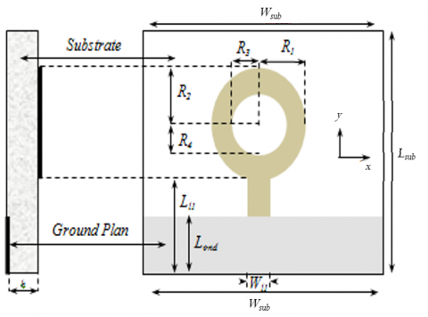
The dimensions of the proposed microstrip antenna are: the size patch (R1 and R2 and inner radii (R3 and R4), located above a substrate of height h and permittivity er, and a mass plane of width Lsub and Wsub, respectively. This structure fed by a characteristic impedance transmission line equals to 50Ω (see Figure 1).
Figure 1. Geometry of the proposed UWB antenna
Subsequently, a parametric study of the UWB antenna is carried out, in order to better analyze the influence of different geometrical parameters of the antenna such as the position and the shape and the width of the ground plane, the thickness of the substrate. on the performance of the antenna and in particular on the VSWR.
In the simulations, with the exception of the parameter of interest, the other parameters are kept constant.
The parametric simulation is carried out with HFSS in which the numerical analysis is based on the Finite Element Method (FEM). The parametric study helps to optimize the antenna performance before the antenna is manufactured and tested experimentally. The antenna is then fabricated on FR4 substrate Printed Circuit Board (PCB) based on the simulation specification with dielectric constant (εr), loss tangent (tan δ) and substrate thickness (h). The resonant frequency of the annular ring printed antenna can be given by Bedra et al. [15]:
$f_{r, m n}=\frac{k v_{0}}{2 a \sqrt{\varepsilon_{r}}}$ (1)
where, $v_{0}$ is the velocity of light in free space, k=2n/(R2-R1) is the wave number, and the integer n denotes the azimuthal variation.
2.1 The effect of the structure thickness ‘h’
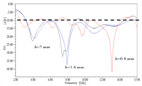
The simulation results for the reflection coefficient for different height values of the substrate are given in Figure 2. This figure illustrates the reflection coefficient of our antenna as a function of frequency (in red). This result shows the presence of resonances at 4.1 GHz, 8.0 GHz, 11.1 GHz and 13.4 GHz with S11 levels of -22dB, -41.6dB, -18.4dB and -15.2dB respectively. The impedance bandwidth, simulated at -10 dB, ranges from 3.1 GHz to 15.5 GHz. It has been found that the optimum value of the height of the substrate is h=1.6mm.
Figure 2. Variation of the reflection coefficient as a function of the frequency taking into account the effect of the height of the dielectric substrate; Lgnd= 23 mm
2.2 The effect of the ground plane length ‘Lgnd’
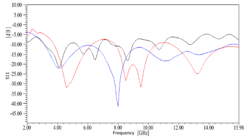
The variation of the frequency as a function of the length of the ground plane is presented in Figure 3. By varying the length of 11.5 mm, 23 mm, and 34.5 mm, it is noted that the resonance frequency decreases.
The resonance frequency of the antennas is very sensitive to the dimensions of the ground plane. But it helps to find the desired frequency since there are several parameters to vary. From Figure 3. It is also noted that the optimum value of the length Lgnd of the ground plane corresponding to Lgnd=23 mm.
Figure 3. Variation of the reflection coefficient as a function of frequency taking into account the effect of the ground plane length; h=1.6 mm and ɛr=4.4
2.3 The effect of the substrate’s permittivity 'ɛr'
In order to observe the influence of the dielectric constant ɛr of the substrate on the adaptation of the antenna, a variation of the dielectric constant ɛr was made for a thickness of the substrate h=1.6 mm.
Figure 4. Variation of the reflection coefficient as a function of the frequency taking into account the effect of the permittivity of the substrate; h=1.6 mm and Lgnd=23 mm
The curve Figure 4 illustrates that an increase in ɛr causes the descent of the reflection coefficient of the proposed antenna.
Table 1. Optimized parameters for our antenna (Unit: mm)
|
Antenna parameters |
Optimal value (mm) |
|
Lsub |
47 |
|
Wsub |
40 |
|
R1 |
6.5 |
|
R2 |
10 |
|
R3 |
6 |
|
R4 |
3.9 |
|
h |
1.6 |
|
Ll |
24 |
|
Wl |
2.6 |
|
Lgnd |
23 |
|
Wgnd |
26 |
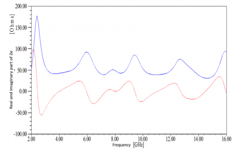
Figure 5 shows the variation of the input impedance of the antenna as a function of frequency. We observe a fairly good.
Figure 5. Real (—) and imaginary parts (----) of the elliptical antenna
The impedance matching that varies around 50 Ohm over the entire bandwidth between 85 Ohm and 36 Ohm; the imaginary part varies between -23.5j and 25.1j in the antenna adaptation band.
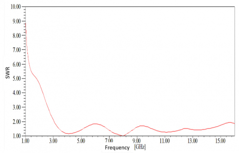
It appears that this antenna (elliptical ring) although optimized in the direction of a drop-in input impedance, displays an impedance varying around 50 Ohms. However, these parameters give it good stability around this value, over a very wide band of frequencies. This good performance is confirmed by calculating the reflection coefficient for a characteristic impedance supply line of 50 Ohms. In this case, the antenna is well adapted over the entire band with a stationary wave ratio of less than 2 (Figure 6).
Figure 6. Variation of the standing wave ratio as a function of frequency
The antenna geometry is designed and simulated in High Frequency Structure Simulator (HFSS). The simulated results in terms of voltage standing-wave ratio, and far-field radiation patterns with neat sketches are discussed in the following.
3.1 Radiation characteristic
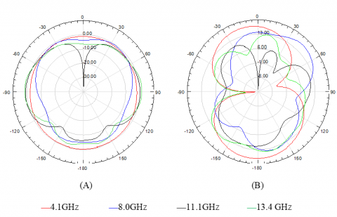
Radiation diagram 2d. The simulated 2d radiation patterns expressed in db (gain) in the two planes e (xoz) and h (yoz) of the proposed antenna at the frequencies 4.1 ghz, 8 ghz, 11.1 ghz and 13.4 ghz. Note that this diagram is stable over the entire band. Moreover, the radiation patterns are symmetrical because the patch has a symmetrical shape around the z axis (see Figure 7).
Figure 7. Radiation diagrams in E (A) and H (B) planes, at frequencies: 4.1, 8, 11.1, and 13.4GHz
Radiation diagram 3d. To characterize the behaviors of the proposed antenna radiation at resonance frequencies and to ensure that they are bipolarized over the entire UWB band, the three-dimensional radiation patterns obtained by HFSS simulation are shown in Figure 8a and 8b.
Figure 8. a) Evolution of Simulated gain in 3 dimensions, at the frequencies: 4.1, 8 GHz; b) Evolution of Simulated gain in 3 dimensions, at the frequencies: 11.1, 13.4 GHz
We can observe different forms of radiation patterns due to the distribution of surface currents in a different way on the elliptical antenna.
3.2 Field mapping
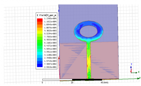
The distribution of the electric field at resonant frequencies is shown in Figure 9. We see that the field is almost uniformly distributed over the elliptical patch.
The Figure 10 shows the distribution of the magnetic field at resonant frequencies. The electric field is confined below the metal plate and the magnetic field rotates around the radiating plate. This field distribution is compatible with a transmission line that has a maximum magnetic field distribution at the line level.
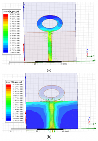
The study of the current distribution on the antenna is then necessary, in order to visualize the impact of the ground plane and the transmission line on the current paths. This work was done at the frequency of 4GHz. Figure 11. indicates the current distribution in the case of a ring elliptical antenna. It may be noted that the currents concentrate first along the line before reaching the elliptical radiating element at its end (Figure 11 (A)).
Figure 9. Distribution of the E field on the radiating element at 4GHz
Figure 10. Distribution of the H field on the radiating element at 4GHz
In these points, the ground plane is truncated, but the currents continue to propagate along the ground plane and the edges of the elliptical patch. This confirms the presence of a progressive wave which continues its propagation after the end of the line.
However, it should be noted in this case the appearance of current arriving in the opposite direction along the end of the ground plane (Figure 11 (B)), from the antenna feed point.
This has the effect of creating a standing wave at the corners of these ground planes with a high current intensity at these points, which limits the adaptation of the antenna by preventing the good propagation of the field lines.
Figure 11. a) Surface distribution of currents on the radiating element, upper face at 4GHz; b) Surface distribution of currents on the radiating element, lower face at 4GHz
For a given application, the choice of the antenna depends on a certain number of criteria among which we emphasize the width of the bandwidth. In recent years several scenarios have been suggested not only to develop the antennas but also to achieve a bandwidth more and more wide than that of conventional antennas [4]. Some applications of antennas require that they be adapted to curved surfaces. In this perspective, the goal of this thesis was the modeling, design and realization of new planar antennas for Ultra-Wide Band (UWB) communications. The UWB can reach speeds of several hundred megabits per second, while maintaining complexity and therefore limited costs. Its large bandwidth also gives it good resistance to interference and multiple paths. Conversely, its low spectral power density allows it to coexist by introducing little interference to surrounding systems [5, 6]. Compared with other kinds of UWB antennas, the size is significantly reduced and the radiation pattern is unidirectional and symmetrical. It is in this context that our work is written. It involves designing and studying planar antennas adapted to the Ultra-Wide Band system.
[1] Gu, X., Taylor, L. (2003). Ultra-wideband and its capabilities. BT Technology Journal, 21(3): 56-66. https://doi.org/1025154914298
[2] Liang, X.L., Denidni, T.A., Zhang, L.N., Jin, R.H., Geng, J.P., Yu, Q. (2011). Printed binomial-curved slot antennas for various wideband applications. IEEE Transactions on Microwave Theory and Techniques, 59(4): 1058-1065. https://doi.org/10.1109/TMTT.2011.2113990
[3] Wong, K.L. (2004). Compact and Broadband Microstrip Antennas. John Wiley & Sons. https://doi.org/10.1002/0471221112
[4] Kaur, S., Ahuja, N. (2013). Design of microstrip patch antenna using defected ground structure for WLAN band. International Journal of Computer Applications, 67(15): 0975-8887. https://doi.org/10.5120/11468-7076
[5] Fistum, D., Mali, D., Ismail, M. (2016). Bandwidth enhancement of rectangular microstrip patch antenna using defected ground structure. Indonesian Journal of Electrical Engineering and Computer Science, 3(2): 428-434. https://doi.org/10.11591/ijeecs.v3.i2.pp428-434
[6] Kaur, G., Singla, G., Kaur, S. (2013). Design of wideband micro strip patch antenna using defected ground structure for wireless applications. International Journal of Advanced Research in Computer Science and Software Engineering, 3(10): 23-27.
[7] Arya, A.K., Kartikeyan, M.V., Patnaik, A. (2008). Efficiency enhancement of microstrip patch antenna with defected ground structure. In 2008 International Conference on Recent Advances in Microwave Theory and Applications, Jaipur, India, pp. 729-773. https://doi.org/10.1109/AMTA.2008.4763036
[8] Singh, G., Momi, R.S. (2013). Microstrip patch antenna with defected ground structure for bandwidth enhancement. International Journal of Computer Applications, 73(9): 14-18. https://doi.org/10.5120/12769-9759
[9] Sadat, S., Fardis, M., Geran, F., Dadashzadeh, G., Hojjat, N., Roshandel, M. (2006). A compact microstrip square-ring slot antenna for UWB applications. In 2006 IEEE Antennas and Propagation Society International Symposium, 67: 173-179. https://doi.org/10.1109/APS.2006.1711670
[10] Jangid, K.G., Tiwari, A., Sharma, V., Kulhar, V.S., Saxena, V.K., Bhatnagar, D. (2016). Circular patch antenna with defected ground for UWB communication with WLAN band rejection. Defence Science Journal, 66(2): 162-167. https://doi.org/10.14429/dsj.66.9329
[11] Liu, L., Cheung, S.W., Azim, R., Islam, M.T. (2011). A compact circular‐ring antenna for ultra‐wideband applications. Microwave and Optical Technology Letters, 53(10): 2283-2288. https://doi.org/10.1002/mop.26295
[12] Meena, M.L., Kumar, M. (2013). Partially hexagonal ground plane UWB elliptical patch antenna. International Journal of Electronics and Communication Engineering & Technology, 4(7): 66-73.
[13] Xu, L., Luo, Y.L., Xin, Z.Y. (2013). A compact monopole antenna for Bluetooth and UWB applications with dual band notched characteristics. In 2013 International Workshop on Microwave and Millimeter Wave Circuits and System Technology, Chengdu, China, pp. 50-53. https://doi.org/10.1109/MMWCST.2013.6814562
[14] Bhattacharya, A., Roy, B., Islam, M., Chowdhury, S.K., Bhattacharjee, A.K. (2016). An UWB Monopole antenna with hexagonal patch structure designed using particle swarm optimization algorithm for wireless applications. In 2016 International Conference on Microelectronics, Computing and Communications (MicroCom), Durgapur, India, pp. 1-5. https://doi.org/10.1109/MicroCom.2016.7522413
[15] Bedra, S., Benkouda, S., Amir, M., Fortaki, T. (2013). Resonant frequency of tunable microstrip ring antenna printed on isotropic or uniaxially anisotropic substrate. Advanced Electromagnetics, 2(2): 6-9. https://doi.org/10.7716/aem.v2i2.194
[16] Meena, M.L., Kumar, M. (2013). Eight shape microstrip patch antenna with crescent slot for wideband applications. In 2013 5th International Conference and Computational Intelligence and Communication Networks, Mathura, India, pp. 49-54. https://doi.org/10.1109/CICN.2013.20
[17] Schantz, H. (2002). Planar elliptical element ultra-wideband dipole antennas. In IEEE Antennas and Propagation Society International Symposium, 3: 16-21. https://doi.org/10.1109/APS.2002.1018152
[18] Schantz, H.G. (2003). Bottom fed planar elliptical UWB antennas. In IEEE Conference on Ultra Wideband Systems and Technologies, San Antonio, TX, USA, pp. 219-223. https://doi.org/10.1109/UWBST.2003.1267836
[19] Chan, K.C.L., Huang, Y., Zhu, X. (2005). A planar elliptical monopole antenna for UWB applications. In IEEE/ACES International Conference on Wireless Communications and Applied Computational Electromagnetics, Honolulu, HI, USA, pp. 182-185. https://doi.org/10.1109/WCACEM.2005.1469557
[20] Ying, C., Zhang, Y.P. (2005). A planar antenna in LTCC for single-package ultrawide-band radio. IEEE Transactions on Antennas and Propagation, 53(9): 3089-3093. https://doi.org/10.1109/TAP.2005.854541
[21] Devana, V.K.R., Rao, A.M. (2019). A novel fan shaped UWB antenna with band notch for WLAN using a simple parasitic slit. International Journal of Electronics Letters, 7(3): 352-366. https://doi.org/10.1080/21681724.2018.1519854
[22] Yoon, H.K., Yoon, Y.J., Kim, H., Lee, C.H. (2011). Flexible ultra-wideband polarisation diversity antenna with band-notch function. IET Microwaves, Antennas & Propagation, 5(12): 1463-1470. https://doi.org/10.1049/iet-map.2010.0126
[23] Nikolaou, S., Tentzeris, M.M., Papapolymerou, J. (2007). Study of a conformal UWB elliptical monopole antenna on flexible organic substrate mounted on cylindrical surfaces. In 2007 IEEE 18th International Symposium on Personal, Indoor and Mobile Radio Communications, Athens, Greece, pp. 1-4. https://doi.org/10.1109/PIMRC.2007.4394348