OPEN ACCESS
After revealing that around 1.3 million deaths every year is due to greenhouse gas emissions and fossil-fuel pollutants being pumped into the atmosphere by transportation industry and vehicles, a global revolt may be needed to accelerate the transition to more clean energy and transport systems. Electric vehicles are considered one of the pillars of eco-friendly solutions since they produce no exhaust gases. Somehow, the limitation of driving mileage still represents an obstacle for developing these vehicles. In general, an electric vehicle propulsion system consists of an electric energy supply system and a traction system; interconnected to each other through a high voltage DC-link. This paper is concerned with the traction system; which constitutes a Brushless Direct Current (BLDC) motor, its voltage source inverter and drive system, in order to tackle this obstacle. It deals with the four quadrants of the speed-torque profile of the motor, with special emphasis on regenerative braking.
electric vehicle, four quadrant operation, BLDC motor, drive system, rechargeable energy storage system, and regenerative braking
Because transportation is considered crucial to our economy and lives, transportation industry is growing continually. The majority of transportation industries and vehicles rely on natural resources; mainly fossil fuels, for their operations. Since these resources are finite and being consumed at a fast rate, their prices increase dramatically. Besides, burning of these fossil fuels results in emission of greenhouse gases, air pollution, and global warming. Rapid consumption of natural resources and environmental impact of combustion of fossil fuels have focused the researchers on sustainable and clean energy sources transportation.
Electric vehicles are considered one of the pillars of eco-friendly solutions since they produce no exhaust gases. Somehow, the limitation of driving mileage still represents an obstacle for developing these vehicles. An electric vehicle propulsion system consists of supply system and traction system; interconnected to each other through an interfacing and control system. This paper is concerned with the electric vehicle traction system, which consists of traction electric motor together with its voltage source inverter and drive system, in order to tackle this obstacle.
Since the electric motor is the main component of any electric vehicle traction system, selecting a proper type of motor with suitable rating is very important. Possible motor candidates for powering electric vehicles are: the induction motor, the switch reluctance motor, and the BLDC motor. BLDC motors are characterized by their capability of offering higher torque and power density together with higher reliability and efficiency, compactness, longer operating life, higher dynamic response, better speed versus torque characteristics, and noiseless operation compared to the motors of the same size and other types. Therefore BLDC motors are preferred for electric vehicle applications [1].
Similar to conventional vehicles, driving in forward and reverse directions, as well as acceleration and deceleration occur frequently, therefore in electric vehicles the inputs of the driver are: a key switch, a forward/reverse direction switch, an accelerator pedal, and a braking pedal. Consequently, dealing with the electric vehicle traction system involves modeling the traction BLDC motor and controlling its drive for its four quadrants of the speed-torque profile.
Traditional vehicle has either hydraulic or pneumatic braking system, which creates friction torque between brake-shoes and wheels to decelerate the vehicle. This braking technique dissipates kinetic energy as heat energy; thereby causes a loss of energy. In urban driving, studies show that about one third to one half of the energy required for operation of a vehicle is consumed during braking [2]. This leads the researches to be focused on energy-saving braking methods.
Electric braking to BLDC motor drive can be implemented by three methods namely; plugging, dynamic braking, and regenerative braking. Although both plugging and dynamic braking methods provide fast braking responses, they are highly dissipative processes. In the plugging method, all the kinetic energy ends up as heat in the motor, while in the dynamic braking method the kinetic energy of the motor and load is dissipated in the form of heat energy through some external resistance. In the regenerative braking method, the kinetic energy of the motor is converted into an electrical one, and is returned back to the supply, thus it is an energy-saving method. By applying the regenerative braking method, the driving range of electric vehicles can be extended by 8-25% depending on the driving condition, and consequently the obstacle for developing electric vehicles due to their limitations of driving mileage is tackled.
The paper is organized in six sections: section (2) describes briefly the components of the propulsion system of the fuel cell/battery powered electric vehicle. Section (3) explains the principle of operation of the traction system components and details the four quadrant operation of BLDC motor. Methods for electric braking of BLDC motor are discussed in section (4). Simulation results of the proposed traction system, with special emphasis on regenerative braking, are detailed in section (5). Finally, the paper concludes with a brief summary in section (6).
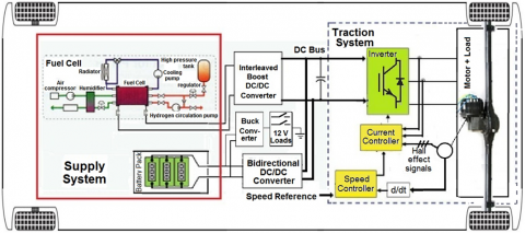
The basic configuration of the fuel cell/battery powered electric vehicle propulsion system is shown in Figure 1. Its traction system constitutes a BLDC motor, and its associated voltage source inverter and drive system.
The power supply system is composed of a fuel cell stack as a main source, and a battery pack as an auxiliary source to power the propulsion motor during starting the vehicle and to assist the propulsion of the vehicle during transients. The fuel cell stack is connected to the DC-bus through a boost converter [1], whereas the battery pack is connected to the DC-bus via a bidirectional DC/DC converter. Original 12 V accessories, such as: lights, horn, and so on are powered by tapping the full battery pack voltage and cuts it down to a regulated 12 V output using a buck DC/DC converter.
It is obvious that high performance electric motor drive systems are central to modern electric vehicle propulsion systems. The benefits accruing from the application of such drives are precision control of torque, speed and position which promote superior electric vehicle dynamical performance [3]. This paper is one of a series of papers by the author on the modeling and simulation of the overall fuel cell/battery powered electric vehicle configuration components. It carries out the four quadrants of the speed-torque profile of the traction BLDC motor, with special emphasis on regenerative braking as an energy-saving method for extending the driving range of the electric vehicle.
Figure 1. Fuel cell/battery powered electric vehicle configuration [1]
Complete electric vehicle traction system is composed of BLDC motor, inverter bridge, rotor position sensor, controller and driver circuit. A BLDC motor is a synchronous motor with permanent magnets on the rotor and armature windings on the stator. It is powered by a DC electric source via an integrated inverter/switching power supply, which produces an AC electric signal to drive the motor, i.e. the motor accomplishes commutation electronically. The commutation instants are determined by the rotor position. Detecting the rotor position in BLDC motors is performed either by position sensors like hall sensor, position encoder and resolver etc. or by sensorless techniques.
Figure 2. Overall structure of the proposed traction drive system
A three-phase BLDC motor has three stator windings, which are oriented 120o apart. When the motor rotates, each winding generates a voltage called back-EMF, which has an opposite polarity to the energized voltage. There are two types of stator windings: trapezoidal and sinusoidal, which refers to the shape of the back-EMF signal. Trapezoidal motor is a more attractive alternative for most applications due to its simplicity, lower price and higher efficiency [4].
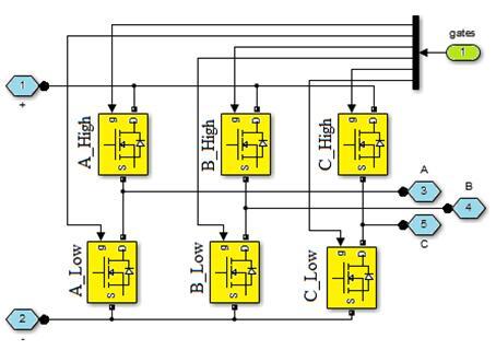
A three-phase trapezoidal stator windings BLDC motor requires three hall sensors to detect its rotor position, each hall sensor is typically mounted 120o apart and produces “1” whenever it faces the North pole of the rotor, i.e. every 60o rotation. Therefore, it takes six steps to complete an electrical cycle. The hall sensor signals are fed to the control circuit which controls the direction and speed of the motor by producing pulse-width modulation (PWM) signals for triggering the electronic switches; MOSFET or IGBT, of the six-step inverter bridge via an interface driver.
Figure 2 shows the overall structure of the proposed traction drive system. The switching sequence for clockwise and counter-clockwise rotations, the current direction and the position sensors’ signals are shown in Table 1. The inverter bridge structure is shown in Figure 3.
Table 1. Switching sequence of BLDC motor
Figure 3. Inverter bridge structure
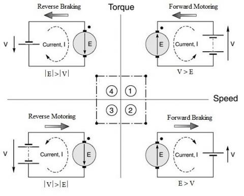
According to the speed-torque profile of the BLDC motor shown in Figure 4, there are four quadrants of operation; forward motoring, forward braking, reverse motoring and reverse braking, respectively.
During motoring modes; first and third quadrants, the magnitude of the supply voltage is greater than the back-EMF, NC (Normally Closed) contacts in Figure 2 are closed and NO (Normally Open) contacts are opened, and thus the energy flows from the supply to the motor. In these modes, both the speed and the torque have the same sign; positive for forward motoring or negative for reverse motoring. Whereas in generating (braking) modes; second and fourth quadrants, the magnitude of the supply voltage is less than the back-EMF, and hence the energy flows from the motor to the supply, i.e. the motor acts as a generator. During these modes, NC contacts are opened and NO contacts are closed to connect the motor to the chargeable battery via the rectifier, to store the generated energy. In such modes, the torque has an opposite sign to the speed, which means a “brake” is being applied to decelerate the motor.
Figure 4. Four quadrant operations
Electric braking to BLDC motor drive can be implemented in three ways namely; plugging, dynamic braking, and regenerative braking. Plugging or plug-reversal is a method of braking obtained by reversing the armature terminals while running, thus both the supply voltage and the back-EMF act in the same direction. The armature current is reversed, thereby producing a braking torque. This current is very high; even larger than when starting from rest. Frequent plugging will cause serious overheating, because each reversal involves the ‘dumping’ of four times the stored kinetic energy as heat in the windings. Although plugging provides fast braking response, it is a highly dissipative process in which all the kinetic energy ends up as heat in the motor [5].
The second type of braking methods is the dynamic or rheostatic braking, which brings the motor to rest position by disconnecting the windings from the power supply and short circuiting them. Short circuiting the windings leads a high current which can damage the windings. To limit this current flowing in these windings, an external resistance called a braking resistance is connected in series with the windings. Thus, dynamic braking is a method of dissipating the kinetic energy of the motor and load in the form of heat energy through some external resistance [6].
The third type of braking methods is the regenerative braking. During its braking period, the kinetic energy of the motor is converted into an electrical one, and is returned back to the supply, i.e. the motor acts as a generator during this period. Thus regenerative braking is an energy-saving method.
Applying the regenerative braking method in an electric vehicle increases the efficiency of the vehicle by recapturing the wasted kinetic energy. This energy is stored in a rechargeable battery storage system during regenerative period, and can be fed back to the inverter mains during peak power demand occasions; such as vehicle acceleration or driving uphill, or during shortage of energy from source.
Thereby, regenerative braking can be a method for extending the driving range of electric vehicles by 8-25% depending on the driving condition, normally it is more effective in urban driving rather than highways whereas little braking occurs, and consequently the obstacle for developing electric vehicles due to their limitations of driving mileage is tackled [2].
The structure of the proposed traction drive system, shown in Figure 2, includes a switching (relay) circuit coupled to the BLDC motor. As discussed before, whenever the motor is operating in the braking modes, NC contacts are opened and NO contacts are closed, thereby the generated voltage gets rectified and energy-regenerative braking operation is established by allowing the charge to be stored in a chargeable battery. When the rechargeable battery storage system is fully charged, in such a rare case, the regenerative braking cannot occur. Therefore a module is inserted after rectification to check the State-Of-Charge (SOC) of the chargeable battery. It allows the energy-regenerative braking operation to be performed until full SOC occurs, then it directs the energy to be dissipated in an external resistive load, i.e. performs dynamic braking operation. It is obvious that the dynamic braking time can be varied by varying the value of resistor.
Although the benefits of using regenerative braking system in electric vehicles, the produced braking power at low speeds is not sufficient and may fail to stop the vehicle in the required time; especially in emergency cases, due to relatively low voltage generated by the motor/generator. Hence, the mechanical braking system is still indispensable for safety actions and for avoiding failure operation of electric energy regeneration. In nowadays electric vehicles, the functions of both mechanical braking and regenerative braking are combined into a single foot pedal; such that the first part of the pedal controls the regenerative braking while the second part controls the mechanical braking.
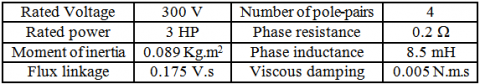
Figure 5 shows the Simulink model of the proposed traction drive system. A 3 HP three phase BLDC motor is used. Its parameters are shown in Table 2 [7].
Table 2. BLDC motor technical specifications
Figure 5. Simulink model of proposed traction drive system
In most traction applications, the BLDC motor control circuit consists of a speed controller and a current controller to control the motor performances. Our proposed speed control loop uses a PI regulator to control the speed of the motor by comparing the referenced speed with the actual speed of the motor. To avoid armature over-current and destabilization of the system due to sudden reference changes, acceleration and deceleration ramps of 1000 rpm/s are put for the speed reference change rate to follow. The controller gains (Kp = 3.3 and Ki = 300) are determined by considering the rotor inertia, the viscous damping, the number of poles, the phase resistance and inductance. The speed controller produces the referenced torque signal for the current controller based on the motor speed and torque relationship.
A hysteresis current controller is used to generate the required PWM pulses based on the reference torque signal, the hall sensors feedback and the phase currents feedback. Hysteresis-band PWM is basically an instantaneous feedback current control method of PWM where the actual current continually tracks the command current within hysteresis-band. These PWM signals are fed to the six-step inverter bridge via an interface driver for triggering the electronic switches.
The simulation is carried out for a time of 3.5 s and a discrete power GUI mode is adopted with 2 ms sampling time. To check the behavior of the proposed traction system, first the motor is operated on no-load condition; that is the applied reference load torque is maintained at zero. The simulation results are given in Figures 6-9.
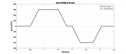
Figure 6. Rotor speed at no-load
The reference speed presented in Table 3, is sent to the 1000 rpm/s rate limiter before entering the speed controller.
Table 3. Reference speed
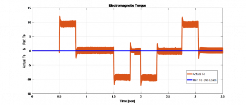
Figure 7. Electromagnetic torque at no-load
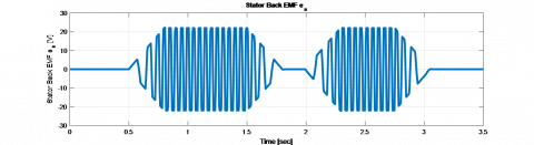
Figure 8. Stator back-EMF at no-load
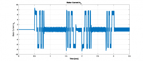
Figure 9. Stator current at no-load
From Figure 6, it can be observed that the rotor speed is exactly following the reference one. The torque in Figure 7 stays around the reference zero value, except during the speed climbing and diving periods it jumps to nearly +11 and -11 Nm, respectively. Figure 8 shows the variation in back-EMF as the speed changes its direction from forward to reverse. Figure 9 shows that the stator current increases during acceleration and deceleration periods, and decays during steady-state speeds.
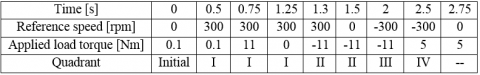
For checking the behavior of the proposed system in the four quadrants of the speed-torque profile of the motor, the reference speed and the applied load torque to the motor are presented in Table 4.
Table 4. Quadrant determination
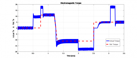
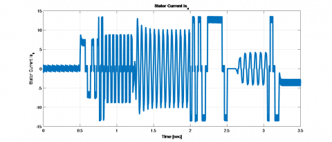
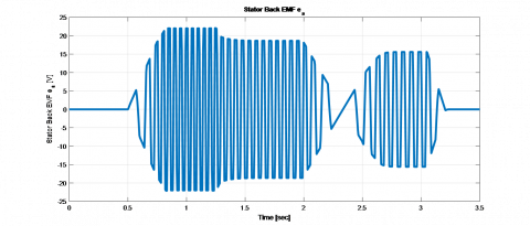
Figures 10-16 show the simulation results for the four quadrants operation of the motor. The speed set point and the torque set point are also shown.
From time t = 0.5 s to 1.3 s, the speed set point is 300 rpm and the applied load torque is positive. That is, the machine is operating in the first quadrant; forward motoring. As can be seen in Figure 10, the actual speed is precisely following the reference with the acceleration ramp.
Figure 10. Rotor speed (four quadrant operation)
Figure 11. Electromagnetic torque
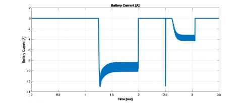
From time t = 1.3 s to 2 s, negative load torque is applied to the motor, while the speed set point is still positive. This implies that a brake is applied, and that the machine is operating in the second quadrant; forward braking. Figure 10 shows a deceleration in the rotor speed. At that time, the motor acts as a generator. NC contacts are opened and NO contacts are closed, and the generated voltage gets rectified. Because the rechargeable battery storage system is not fully charged, the energy-regenerative braking operation is established by allowing the charge to be stored in the chargeable battery, as can be seen in the battery parameters Figures 14-16.
Figure 12. Stator current
During the time t = 2 s to 2.5 s, both the speed set point and the applied load torque to the motor are negative. That is, the machine is operating in the third quadrant; reverse motoring. NO contacts are opened and NC contacts are closed. As can be seen in Figure 10, the actual speed tries to follow the speed set point ramp by decreasing the speed to zero and starting to speed up with a rotation in reverse direction.
At time t = 2.75 s, the speed set point is commanded to reach zero value, but due to the 1000 rpm/s rate limiter, it returned to zero value at 3.02 s. From time t = 2.5 s to 3.02 s, positive load torque is applied to the motor, while the speed set point is still negative. This implies that a brake is applied, and that the machine is operating in the fourth quadrant; reverse braking.
Figure 13. Stator back-EMF
Figure 14. Battery voltage
As shown in Figure 10, the actual speed is no longer following the speed set point ramp but a deceleration in the reverse direction occurs. Again during that time, the motor acts as a generator. NC contacts are opened and NO contacts are closed. The motor kinetic energy is converted into an electric one and is stored in the rechargeable battery storage system, as shown in the battery parameters Figures 14-16.
Figure 15. Battery current
Figure 16. Battery state-of-charge
Figure 12 shows the stator current, where the transition from one quadrant to another is clearly observed in this waveform. Figure 13 shows the variation of the stator back-EMF relative to the amplitude and direction of the speed. It is observed that its amplitude is increased by increasing the speed and is reduced when braking is applied at time 1.25 s.
The demand for greener standards of living and production in today’s world has steered automotive industries towards the development of an environmentally cleaner transportation in near future. Therefore electric vehicles are going to be popular due to their zero exhaust gases emission. Somehow, the limitation of driving mileage still represents an obstacle for developing these vehicles.
The objective of this paper was to study and improve the efficiency of the electric vehicle traction system in order to tackle this obstacle. Operational characteristics and mathematical modeling of the components of the traction system; BLDC motor, its voltage source inverter and drive system, are detailed. The four quadrant operation, along with the different braking methods of BLDC motor drive is discussed. Discussion proved that the energy management in the electric vehicle can be well improved through the braking system used in it.
A simple scheme of an electric vehicle traction drive system has been presented and successfully simulated. The simulation results showed that the proposed system is working properly and the motor reverses the speed smoothly. Energy improvement is achieved by applying the regenerative braking method which recaptures the motor wasted kinetic energy, converts it into an electrical one, and then returns it back to the supply, thereby extends the driving range of electric vehicle.
[1] Youssef A. (2017). Multiphase interleaved boost DC/DC converter for fuel cell/battery powered electric vehicles. World Journal of Modelling and Simulation 13(3): 200-211.
[2] Abhale Y, Nigam P. (2015). Review on regenerative braking methodology in electric vehicle. International Journal of Advanced Research in Electrical, Electronics and Instrumentation Engineering 4(7): 6380-6386. https://doi.org/10.15662/ijareeie.2015.0407083
[3] Miller J. (2010). Propulsion systems for hybrid vehicles. IET. Renewable Energy. 2nd Edition.
[4] Singh C, Kulkarni S, Rana S, Deo K. (2013). State-Space based Simulink modeling of BLDC motor and its speed control using fuzzy PID controller. International Journal of Advances in Engineering Science and Technology 2(3): 359-369.
[5] Hughes A. (2006). Electric motors and drives: fundamentals, types and applications. Elsevier.
[6] Rakesh M, Narasimham P. (2012). Different braking techniques employed to a brushless DC motor drive used in locomotives. International Electrical Engineering Journal 3 (2): 784-790.
[7] Tremblay O. (2006). Modélisation, simulation et commande de la machine synchrone à aimants à force contre-électromotrice trapézoїdale. Maîtrise en génie électrique dissertation. Ecole de technologie supérieure, Université du Québec, Montréal, Canada.