OPEN ACCESS
In order to accurately analyze the stress and strain ø6000 disc pelletizer plate body, weight problem solving high redundancy disk body design caused excessive, calculated on the basis of a comprehensive body of load on the disc, the system was established in ANSYS parametric model plate body. In the applied load and set constraints, based on the plate body was static analysis, it reveals the distribution of stress and strain under maximum load conditions head body. By setting the strength conditions, the disc body main design parameters were optimized to solve. Analysis showed that, ø6000 disc pelletizer strength redundancy disk body is large, which is the main cause of increase in weight of the equipment; Optimized design parameters for the device fine design provides accurate reference data, equipment weight loss effect is obvious.
ø6000 disc pelletizer, plate body, finite element, analysis, optimization
ø6000 disc pelletizer [1] is an important equipment pellet production, strong production capacity, good quality pelletizing, but because of the huge equipment, poor working conditions, job stability which is also facing a huge challenge. Currently, domestically produced disc pelletizer mostly imitation of foreign products, not mastered the core design technology. Information from the public view, the disc pelletizer study abroad mainly in the field of transmission and blade system, almost no load calculation, the results of parts of the structure and strength of the study, but the lack of research ø6000 disc pelletizer [2]:
Due to the lack of theoretical support load calculations and structural design, the design process, design experience with domestic enterprises often blindly increase the size of the parts, so pelletizer major parts meet the complex conditions of the strength and stiffness requirements. Resulting in a substantial increase in the overall weight of the machine-made ball, but it reduces the stability and reliability of the equipment [14]. Plate body as a main component pelletizer directly accommodate ore powder, coordinated action and scraper system, making the ball function. Thus, both major components of the disk body pelletizer, the key pelletizing process is complete. Disk body suffered complex load, poor working conditions, peak load large, its stability made directly determine the quality and efficiency of the overall work of the dome. Restricted foreign confidentiality of information, there is no publicly available information base plate body design, so that the disc body is designed to experience the hardest hit, but also pelletizer concentrated amount of redundancy in the design of components. A domestic enterprise manufacturing ø6000 disc pelletizer, blindly increasing the size of the plate member, resulting in huge volume, weight, high. Appear in the use of the disk body instability, some parts of the deformation and damage of the phenomenon, and the disk body bulky, low productivity, product cost reduction difficult.
To find the disc problem ø6000 disc pelletizer body design, effectively reducing the disk body weight, reducing overall manufacturing costs pelletizer, the paper will be a detailed analysis of the distribution of ore powder and accurate calculation based on the load plate body, using a large ANSYS finite element analysis software to parameterize the disc body build; applying loads and constraints, based on the plate body stress and strain analysis, found that the distribution of the disk body at full load stress and strain to find design inadequate; on the basis of analysis, through the optimization of the design parameters of solving the optimization program to get the disk body design, a reference to the actual engineering design, to reduce the weight of the target disk.
2.1 Quality disc ore body powder
2.1.1 Distribution of the disc body of ore powder
As shown in Figure 1, when the disc pelletizer work, pellet feed—ore powder continue to inject plate body, disk body uniform rotation, ore powder rotary drive, in the role of doctor blade system, constantly generating pellets and discharge tray body [15]. Balling in a dynamic process, the disk body and the doctor blade system coordination role, stirring continuously ore powder. Therefore, the distribution of the disc in different body positions ore powder will show a different state, but also to the different parts of the disk body applied the different load.
Figure 1. Distribution of ore when disc pelletize working
Observe and analyze actual pelletizing process found, in the ore particles plate body under the action of its own weight and centrifugal force, direction of the disc diameter direction of the formation of a “slag accumulation zone” and “slag into a ball zone” in two distribution. In addition, to increase the wear resistance of the disk body, often welded circular steel columns scale stencil or on the disk body floor. So pelletization process, ore powder forming a protective layer fills in the gap scale stencil or cylindrical in, also known as the primer layer. Therefore, the disc pelletizer disc body of ore powder is mainly distributed in the near side of the disc slag accumulation zone, within a flange near the center of the plate body into a ball area and the bottom surface of the upper portion of the bottom plate body material layer in three areas. Mineral particles although the three regions to exchange and flow, but overall remains stable. It is the weight of the ore powder three regions, is applied to the disc main body load, therefore, calculate the mass of three parts ore powder is critical computing load plate body suffered.
2.1.2 Quality disc ore body powder
According to the design information ø6000 disc pelletizer plate body, Take the radius of the disk R=3000 mm, A flange height H=600 mm, The thickness of the bottom end plate body material layer h=50 mm (Also verification through on-site measurements); By actual measurement, accumulation zone ore powder evenly deposited on the edge of the half-plate body, its cross-sectional shape of the side length L=600 mm equilateral triangle. For ease of calculation, we will simplify the accumulation zone to a length of half the circumference of the plate body, square cross-section (side length L) of the cuboid. Disc pelletizer process parameters are as follows: Speed 9 rpm, the inclination of the disk body 43 ° ~ 53 °, ore powder packing ratio in the disc body is 10% ~ 20% and water content of 7.5% ~10.5%. Ore powder characteristics used in Table 1.
Table 1. The properties of ore
|
Name |
The bulk density ρ(t/m3) |
Angle of repose (°) |
|
|
Move |
Quiet |
||
|
Iron ore(Iron 53% ~ 60%) |
2.4 ~ 2.9 |
30 ~ 35 |
40 |
|
Iron ore(Iron less than 33%) |
2.2 |
30 ~ 35 |
38 ~ 40 |
Note: Internal friction coefficient f = tan (Angle of repose)
Taken in accordance with the principle of maximum load, quality ore powder filling amount calculated in accordance with the maximum, That volume V is calculated after each region, in accordance with the maximum packing density ρ = 2.9 t/m3 and a maximum filling rate of 20%, calculate the mass of each region ore powder Q. According to equation (1) Calculate the mass of the three regions and the entire disc in vivo ore powder results in Table 2.
$Q=V \rho$ (1)
where: Q—Ore powder quality (t); V—Ore powder volume (m3); ρ—Ore powder maximum packing density (t/m3)
(1)Quality backplane chassis body material layer ore powder Q1:
Primer layer volume:
$V_{1}=\pi R^{2} h=\pi \times 3^{2} \times 0.05=1.41\left(\mathrm{m}^{3}\right)$ (2)
Ore powder quality primer layer:
$Q_{1}=\rho V_{1}=2.9 \times 1.41=4.10(\mathrm{t})$ (3)
(2) The total mass of the disk body of ore powder Q:
Plate body size:
$V=\pi R^{2} * H=\pi \times 3^{2} \times 0.6=16.965\left(\mathrm{m}^{3}\right)$ (4)
The total mass of ore powder:
$Q=\rho V * 0.2=2.9 \times 16.965 \times 0.2=9.84 (\mathrm{t})$ (5)
(3) Ore powder mass accumulation zone Q2:
Stacking zone ore powder volume:
$V_{2}=\frac{1}{2} * L^{2} * \pi R=\frac{1}{2} \times 0.6^{2} \times \pi \times 3=1.696\left(\mathrm{m}^{3}\right)$ (6)
Stacking zone ore powder quality:
$Q_{2}=\rho V_{2}=2.9 \times 1.696=4.92(\mathrm{t})$ (7)
(4) Quality ore powder into a ball zone Q3:
$Q_{3}=Q-Q_{2}=9.84-4.92=4.92(\mathrm{t})$ (8)
Table 2. Volume and mass of ore powder in each area Volume (m3)/mass (t)
|
The entire disc body |
Hearth layer |
Accumulation area |
Balling zone |
|
V=16.965 |
V1=1.41 |
V2=1.696 |
|
|
Q=9.84 |
Q1=4.10 |
Q2=4.92 |
Q3=4.92 |
2.2 Calculations disc body suffered during load
Ignore plate body suffered other loads, set load ore powder produced by the body weight of the disc is the main load. Factors to consider ore powder, add water, Ore powder weight of each region to zoom 10% (from experimental results). Taking dynamic load factor φ=1.1, acceleration of gravity g=9.8 N/kg. According to technology standards, Work inclination ø6000 disc pelletizer plate body is 43 ° ~ 53 °. When the disc angle is 43 °, the disc body being subjected to the maximum pressure; when the tilt angle of the disk body is 53 °, the positive pressure side of the disk plate body suffered the most. Therefore, in accordance with the formula (9) and set the angle of the disc is 43 ° to calculate the disk body work process suffered the maximum load. The results of the regional load ore powder is applied to the disc body in Table 3.
$P=\frac{Q g \times 1.1 \times \varphi}{S}$ (9)
where: P—Load (MPa);Q—Ore powder quality (t);g—Acceleration of gravity (N/kg);φ—Dynamic load factor;S—Plate body force area (m2)
$P_{1}=\frac{Q_{1} g \times 1.1 \times \varphi}{S} \times \cos 43^{\circ}$
$=\frac{4.1 \times 10^{3} \times 9.8 \times 1.1 \times 1.1}{\pi \times 3^{2}} \times \cos 43^{\circ}$
=0.00126 (MPa) (10)
$P_{2}=\frac{Q_{2} g \times 1.1 \times \varphi}{S_{2}} \times \cos 43^{\circ}+P_{1}$
$=\frac{4.92 \times 10^{3} \times 9.8 \times 1.1 \times 1.1}{0.5 \pi \times\left(3^{2}-2.4^{2}\right)} \times \cos 43^{\circ}+P_{1}$
$=0.009644(\mathrm{MPa})$ (11)
$P_{3}=\frac{Q_{3} g \times 1.1 \times 1.1}{S_{3}} \times \cos 43^{\circ}+P_{1}$
$=\frac{4.92 \times 10^{3} \times 9.8 \times 1.1 \times 1.1}{0.5 \pi \times 2.4^{2}} \times \cos 43^{\circ}+P_{1}$
$=0.005976(\mathrm{MPa})$ (12)
$P 4=\frac{Q_{2} g \times 1.1 \times 1.1}{S_{4}} \times \sin 53^{\circ}$
$=\frac{4.92 \times 10^{3} \times 9.8 \times 1.1 \times 1.1}{\pi \times 3 \times 0.6} \times \sin 43^{\circ}$
$=0.007036(\mathrm{MPa})$ (13)
Table 3. Each portion of the disk body suffered load MPa
|
Primer layer to bring the bottom surface of the disk load P1 |
Ore powder accumulation area to the bottom surface of the disk load P2 |
Ore powder into the ball area of the bottom surface of the disk to load P3 |
Ore powder accumulation zone to the disc loading body side dish P4 |
|
0.00126 |
0.009644 |
0.005976 |
0.007036 |
3.1 Parametric Modeling head body
Disc pelletizer plate body by the middle of the basin, side dish and side bracket components. To facilitate the analysis and calculation of the structure during the modeling process and load the disc bodies were reasonably simplified. To achieve optimization of the design parameters should be established parametric finite element model of the disk body [16], and extracts design variables as the characteristic parameters of the model based on design principles, design parameters are also shown in Table 4. These optimization design model of the design variables.
Table 4. The initial value of Design variables
|
Variable Code |
The initial value of the variable(mm) |
Variable corresponding design parameters |
|
TK1 |
16 |
Central plate floor thickness |
|
TK2 |
16 |
Rib thickness |
|
TK3 |
16 |
Circular vertical thickness |
|
TK4 |
10 |
Plate vitro wall thickness |
|
TK5 |
12 |
Side plate floor thickness |
|
TK6 |
8.5 |
Side bracket beam web thickness |
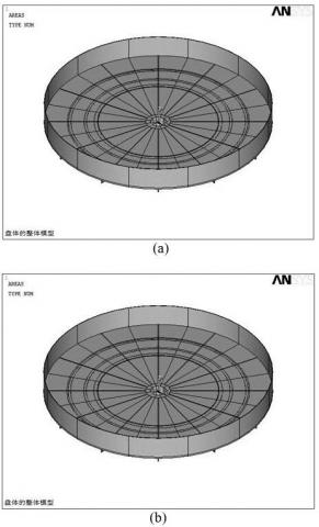
According to the initial value of the variable, directly in ANSYS create parametric models 1/12 disc body is shown in Figure 2. Disc body integral model by synthesized as shown in Figure 3, Figure 3 (a) for the front plate body, Figure 3 (b) for the body on the back plate.
Figure 2. The one twelfth of the disk’s modle
Figure 3. The overall model of the disk
3.2 Mesh plate body parametric model
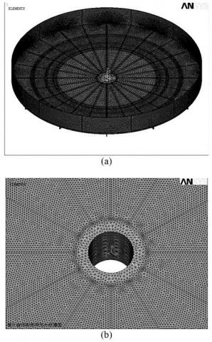
Since the structure of the disc body is more complex, irregular shape, so the use of the freeway of meshing meshing in ANSYS [17]. Model plate body using a Smart Size meshing, takes a value of quality level 1, Select the unit type SOLID45. Body model after meshing plate, its unit number is 1382371, the number of nodes 449599. Finite element model of the entire disk volume model after meshing as shown in Figure 4 (a), Central bore partial mesh case Figure 4 (b).
Figure 4. The meshing of the whole disk level
4.1 Disk body suffered applied load
Suffered head body including the weight of the load, load rotation centrifugal force generated by the weight of mineral powder. Due to the small plate body weight and influence of centrifugal force, therefore, the weight of the load to produce ore powder as a main load analysis. According to the previous analysis of the distribution of the disc body of known ore powder, separately from the load plate body suffered primer layer load, load and stacking area into a ball area loads, which are acting on the bottom and side of the reel body. We first various loads are applied to different regions of the disk body, and then you can get the disk body synthesis load model.
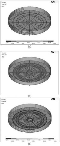
(1)The bottom surface of the disk body accumulation zone is the applied load side dish: Full load conditions, due to the rotation of the disc is tilted, So while ore powder accumulation area applied load P2 to the bottom of the plate body, also on the side of the reel body applied load P4. Specific numerical values in Table 3 above two loads. After applying a load plate body model shown in Figure 5 (a).
(2)Suffered load is applied to the bottom surface of the disk body ball area: The ball into the bottom surface of the disk body region suffered loads include loads P1 primer layer is applied and a ball zone ore powder load applied P3. Specific numerical values in Table 3 above two loads. After applying a load plate body model shown in Figure 5 (b).
(3)A whole load plate Model: the above two load plate body synthesizes model, you can get the distribution of the entire disc body suffered full load conditions, shown in Figure 5 (c).
Figure 5. The loading chart of the disk
4.2 Setting disk body model boundary conditions
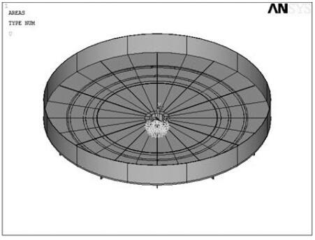
To improve the accuracy of finite element analysis, according to actual working conditions to set boundary conditions [18]. According to the actual conditions ø6000 disc pelletizer plate body plate boundary condition it is mainly to eliminate rigid displacement plate body, the center hole of the disk that is connected to the body and the spindle sleeve all-constrained manner, in order to eliminate the disc along its axis axial displacement, See Figure 6. In addition, the foregoing analysis shows that, when the plate body angle is 43 °, the bottom surface of the disk body suffered the largest load, the worst working conditions.
Figure 6. Setting the boundary conditions of the disk
4.3 Stress and strain analysis of full disk body condition
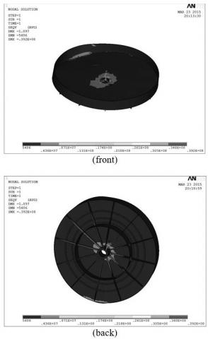
In the disk body 43 ° tilt angle, the disc body in the harshest conditions. By ANSYS analysis and calculation system, we have been stress cloud plate, strain and displacement cloud cloud. Figure 7 is a finite element analysis by von-Mises stress cloud computing available, Figure 8 (a) is the overall change in the displacement map disc body, Figure 8 (b) is the strain diagram disc body.
Figure 7. Von Mises stress distribution of the disk
Figure 8. The displacement and strain of the disk
Figure 7 shows, the center hole of the disc body has obvious stress concentration at which the maximum stress appears. ANSYS software by maximum stress node inquiry shows, the maximum stress occurs on the node number 11733, the maximum stress value of about 39.2 MPa. Figure 8 shows, the maximum displacement occurs at the outer wall of the disc body of the disc body, the maximum displacement amount of 1.897 mm; the maximum strain occurs at the center of the disk body hole, and stress concentration area is consistent. Displacement and strain plate body is small, indicating that the stiffness of the plate body fully meet the requirements.
According ø6000 disc pelletizer design information shows, plate material is a Q235A, its yield limit σS = 235 Mpa. Safety factor n=1.5, Plate material calculated allowable stress [σ].
$[\sigma]=\frac{\sigma_{s}}{n}=\frac{235}{1.5}=156.67$ (14)
In the worst conditions, the maximum stress plate body when fully loaded is 39.2 MPa, far less than the allowable stress 156.67 MPa. Thus, the strength of the disc body not only meets the requirements, and the design is very large amount of redundancy, which is caused mainly due to the high weight of the equipment. The results show that having a larger disk space optimized design, by optimizing the design, appropriate to reduce the size of the value of the disk body parts can reduce the weight of the device.
5.1 Plate body optimal mathematical model and optimization algorithm determines
$f(x)=\min \left(\sum_{k=1}^{n} \Delta V\right)$ (15)
where: n—The total number of plate finite element model unit; ΔV—The volume of the k-th finite element (mm3)
Disk body stiffness constraints: The maximum deformation of the disk structure optimizedεmax≤1.897 mm.
In summary, the disk body design variables to optimize each design model and its value range, optimization constraints and objective function as shown in Table 5.
Table 5. Optimization variables and their Ranges
|
Optimization variables |
Physical meaning / unit |
Ranges |
|
Design variables |
Central plate floor thickness TK1/mm |
[1,16] |
|
Rib thickness TK2/mm |
[1,16] |
|
|
Circular vertical thickness TK3/mm |
[1,16] |
|
|
Plate vitro wall thickness TK4/mm |
[1,10] |
|
|
Side plate floor thickness TK5/mm |
[1,12] |
|
|
Side bracket beam web thickness TK6/mm |
[1,8.5] |
|
|
Restrictions |
Disc structure maximum stress σmax/MPa |
≤60 |
|
Deformation optimized εmax/mm |
≤1.897 |
|
|
The objective function |
The total volume of the disk body model unit V/mm3 |
min |
(4) Determining an optimal algorithm: Although the disk body bulky, complex structure, a huge number of cell division, but in order to get a more accurate optimization results, select the first order optimization algorithm optimization solution [19, 20], and set the optimization iterations 30 times, until the solution convergence, the optimization process automatically stops, get optimal results.
5.2 Optimization results and analysis
The maximum stress value of the disk body is set to 60 MPa, obtained the following results shown in Table 6 by the optimal solution. To meet the needs of actual manufacturing optimization variable values have been adjusted, the design variables adjusted value. Upon inquiry ANSYS system [21], Unit volume model optimized for the disc body was 0.221 m3.
Table 6. The results of optimization variables after optimized
|
Design variables / unit |
Initial design |
Optimization Results |
Adjusted results |
|
Central plate floor thicknessTK1/mm |
16 |
3.23 |
4.00 |
|
Rib thicknessTK2/mm |
16 |
1.61 |
2.00 |
|
Circular vertical thicknessTK3/mm |
16 |
1.00 |
1.00 |
|
Plate vitro wall thicknessTK4/mm |
10 |
1.08 |
2.00 |
|
Side plate floor thicknessTK5/mm |
12 |
1.00 |
1.00 |
|
Side bracket beam web thickness TK6/mm |
8.5 |
7.40 |
8.00 |
To test optimization results, the disc design variable volume model parameter values changed to the value adjusted to re-establish the plate body model, and applied loads and constraints, the analysis of stress and displacement contours obtained after solving the model optimized, As shown in Figure 9 (a) and Figure 9 (b).
Figure 9. The von Mises stress distribution and displacement of the disk after optimized
Analysis Figure 9 (a) and (b) can draw the following conclusions:
(1)Optimized disk body maximum displacement of 1.585 mm, less than the initial deformation of 1.897 mm, optimized to meet the constraints.
(2)Optimized disk body maximum stress of 44.3 MPa, less than 60 MPa, to meet the optimization constraints.
(3)The total volume of about optimized disk body V1=0.243 m3. Since the materials used for the disk body Q235A steel, its density ρ=7850 kg/m3. So after optimizing the quality of the disc body is:
W1=V1ρ=0.243×7850 =1907.55 (kg) (16)
The total volume of the unit in accordance with the initial setting design variables establish disk body model is about V0=0.845 m3, thus optimizing the quality of premarket body:
W0=V0ρ=0.845×7850=6633.25 (kg) (17)
So after optimizing disk body mass reduction:
ΔW= W0- W1=6633.25-1907.55=4725.70 (kg) (18)
Therefore, to optimize the disk after body mass reduction of about 4.7 t, reached the body weight of the purpose of the disk, and the weight loss effect is obvious. Actual engineering design, optimization can be based on the results of the above, appropriate adjustments to the value of each parameter disk body, in order to meet the needs of equipment manufacturers.
In the analysis ø6000 disc pelletizer machine works on the basis of the distribution of the disc to determine ore body powder, and accurately calculate the load of each part of the disc body ore powder is applied, it has been under full load plate body suffered the main load of the specific values; through the establishment of a parametric model of the disk body, stress, displacement and strain plate full body condition was solved, and the main design parameters are optimized, the following conclusions:
(l) Full load conditions, the disc quality is the main body of ore powder load plate body suffered. Ore powder mainly in the accumulation zone, as the ball area and the bottom plate body. According to the analysis and field measurements, you can calculate the mass region ore powder, it laid the foundation for the calculation of the maximum load plate body.
(2) Inclination of 43 ° maximum load suffered the disc body, including the primer layer to bring the bottom surface of the disk loading, loading ore powder on the bottom and side dish plate body applied accumulation zone, a mineral powder tray bottom surface area of the ball applied load. Consider the need for spray powder ore pelletizing process in the enlarged 10% load. On the basis of the calculated three parts flour quality ore on accurately calculate more than four load plate for the stress and strain analysis of the foundation.
(3) To facilitate the optimization of late, by setting the main design parameters, the establishment of a parametric finite element analysis model of the plate body, using free meshing manner sub-network; choose to analyze the disk body angle is 43 ° when applying loads and constraints based on the analysis of the distribution of solving stress, displacement and strain the pan body. The center hole of the disc body has obvious stress concentration, where the maximum stress value of about 39.2 MPa, far less than the disk material allowable stress; maximum displacement occurs at the outer wall of the disc body at the head body, maximum strain place in the center hole of the disc body, and a smaller displacement and strain. The results show that the strength and stiffness of the disc body not only to meet the requirements, but also designed a very large amount of redundancy, which is caused mainly due to the high weight of the equipment; plate having a large design space optimization, by optimizing the design parameters can be reduce the weight of the device.
(4) In the main parameters for optimizing disk body variables to parameter values and initial design allowable stress and strain constraint is selected first order optimization algorithm optimization solution; to minimize the total volume of the disk unit for the optimization goal, in σmax≤60 MPa stress conditions were optimized to solve the plate body, obtain the specific value of optimization variables, and in accordance with manufacturing requirements be adjusted. Adjusted using parametric modeling and stress and strain analysis. The results showed that: at σmax≤60 MPa stress constraints, numerical design parameters significantly decreased, indicating that the original design redundancy is very large; in accordance with the parameters optimized design, can reduce the disk body mass 4.7 t, dish body weight effect is obvious.
Analyze and optimize the results of this paper have clear guidance for the actual design ø6000 disc pelletizer. Improving the stability of the device to work from the perspective of the future may be more load range included in the analysis, and the plate body to carry out modal analysis. The results will be closer to the actual working conditions, and to provide more accurate data for the design of reference.
[1] Yimin Zhang, Pellet Production Quiz, Beijing: Metallurgical Industry Press, 2005.
[2] Xingman Xu, “China pellet production technology status and development trend”, presented at Iron Production Technology.
[3] Minjie Qiu, “Analysis and improved design of a new type disk pelletizer,” Non-Ferrous Metallurgical Equipment, no. 2, pp. 16-18, 2008. DOI: 10.3969/j.issn.1003-8884.2008.02.005.
[4] Youduo He, “Pelletizing disc pelletizer motion analysis,” Sintering and Pelletizing, no. 5, pp. 1-7, 1981. DOI: 10.13403/j.sjqt.1981.05.001.
[5] Xinji Wang and Changhua Wang, “Computer simulation and parameters optimization for rotary cutter bar of balling disc,” Sintering and Pelletizing, vol. 32, no. 5, pp. 11-14, 2007. DOI: 10.13403/j.sjqt.2007.05.002.
[6] Kun Qiu, Zhiming Song and Minghua Bai, “Locaequation and trajectory analysis for rotary cutter bar of balling disc,” Heavy Machinery, no. 3, pp. 48-51, 2008. DOI:10.13551/j.cnki.zxjxqk.2008.03.008.
[7] Kun Qiu, Zhiming Song and Xinli Hu, “Studies on motorpower of discballing machine,” Heavy Machinery, no. 2, pp. 18-21, 2008. DOI: 10.13551/j.cnki.zxjxqk.2008.02.009.
[8] Kun Qiu and Minghua Bai, “ø7.5m Disc pelletizer design,” Hoisting and Conveying Machinery, no. 4, pp. 28-31, 2009.
[9] Kun Qiu and Minghua Bai, “Design and trajectory of ø7.5m disc pelletizer analog electric scraper,” Hoisting and Conveying Machinery, no. 6, pp. 70-71, 2009.
[10] Minghua Bai, “Design and performance analysis of disc pelletizer electric scraper,” Heavy Machinery, no. 11, pp. 23-28, 1984. DOI: 10.13551/j.cnki.zxjxqk.1984.11.003.
[11] Yuan Leng, “The rotating scraper of disc balling machine’s optimization control system, master’s degree thesis,” M.S. thesis, Dept. Control Eng., Wuhan University of Science and Technology, Wuhan, China, 2012.
[12] Zhiyuan Wu, “The pelletizing disc control based on the RBF NN,” M.S. thesis, Dept. Control Eng., University of Science and Technology Liaoning, Anshan, China, 2008.
[13] Zhijian Peng, “Study on improvement of technological function of balling discs,” Research on Iron and Steel, vol. 126, no. 3, pp. 4-6, 2002. DOI: 10.3969/j.issn.1001-1447.2002.03.002.
[14] Kuangwu Ye, “The present state and the forecasting of our country pelletizing industry,” Sintering and Pelletizing, vol. 28, no. 1, pp. 1-4, 2003. DOI: 10.13403/j .sjqt.2003.01.001.
[15] Xiaohui Fan, Linqing Dai and Wei Wang, “Progress of china pellet production,” presented at Efficient Beneficiation Processing and Utilization Academic Research and Technological Achievements Exchange.
[16] Peter C. K., Ansys Engineering Analysis System: Theoretical Manual, Swanson Analysis Systems, New York, 1989.
[17] Xiuhui Zhang,Renxi Hu and Shiiting Kang, ANSYS14.0 Finite Element Analysis From the Entry to the Master, Beijing: China Machine Press, 2012.
[18] Jinlong Wnag, Qingming Wnag and Weizhang Wang, ANSYS12.0 Finite Element Analysis and Analytical Paradigm, Beijing: Machine Press, 2010.
[19] Homaifar A., Qi C. X. and Lai S. H., “Constrained optimization via genetic algorithms,” Simulation, vol. 62, no. 4, pp. 242-254, 1994. DOI: 10.1177/003754979406200405.
[20] Tong L. Y. and Lin J. Z., “Structural topology optimization with implicit design variable: optimality and algorithm,” Finite Elements in Analysis and Design, vol. 47, no. 8, pp. 922-932, 2011. DOI: 10.1016/j.finel.2011.03.004.
[21] Gordon S. G. and Robert S. S., Optimization: Theory and Practice, New York: MeGraw-Hill Book Company, 1970.