Mahesh Singh* | Shimpy Ralhan | Mangal Singh | Rahul Baghel
© 2024 The authors. This article is published by IIETA and is licensed under the CC BY 4.0 license (http://creativecommons.org/licenses/by/4.0/).
OPEN ACCESS
This experimental study investigates the performance of Lead Acid Battery driven Electric Rickshaws (E-Rickshaws) enhanced with a Capacitor Bank. With a growing demand for sustainable urban transportation solutions, E-Rickshaws have emerged as a promising option. However, challenges such as limited battery life and variable performance under different load conditions persist. In this research, we explore the application of a Capacitor Bank circuitry to mitigate these challenges. The study involves a series of performance tests conducted on E-Rickshaws equipped with the proposed hardware model. Key parameters, including charging current, charging time, and discharging current under varying load conditions, are rigorously analyzed. Our experimental results reveal substantial improvements in E-Rickshaw performance when compared to conventional Lead Acid Battery-driven models. Notably, reductions in starting current and minimized power fluctuations, especially under full load conditions, lead to a smoother and more efficient driving experience. Crucially, the extended battery life resulting from these hardware enhancements demonstrates the economic viability of the modified E- Rickshaw prototype. This research contributes valuable insights into the sustainable transformation of urban transportation, with implications for both performance optimization and economic feasibility in the E-Rickshaw industry.
electric auto rickshaw, battery, modes of discharge, battery life
Auto rickshaws, once manually pulled by individuals for transportation, have evolved significantly over time to become a crucial mode of conveyance in Asia, serving both passengers and cargo needs [1]. The journey of these three-wheeled vehicles through history is fascinating. In 1914, recognizing their potential for citizen transport, authorities began to regulate rickshaws. However, it was in the 1930s when cycle- based rickshaws gained immense popularity in India, ultimately becoming the dominant means of transport by 1935. The transition to motorized rickshaws, powered by fossil fuels, occurred in 1957.
These auto rickshaws hold a unique position in the bustling traffic landscape of India. Their affordability and ability to navigate congested roads make them indispensable. Yet, their widespread use has also given rise to a significant environmental concern: pollution resulting from inadequate maintenance and the use of low-quality fuel [2]. Recognizing the critical role these rickshaws play in local transportation, electrification emerged as a compelling solution [3, 4].
Electric Rickshaws (E-Rickshaws) have emerged as a promising and eco-friendly mode of urban transportation in many parts of the world, particularly in densely populated urban areas. With their compact size, zero emissions, and affordability, E-Rickshaws offer a viable solution to the challenges of urban mobility while addressing environmental concerns.
The advent of electric rickshaws marked a transformative shift. Unlike their conventional counterparts that relied on Internal Combustion Engines (ICE), electric rickshaws harnessed the power of electrical motors for propulsion [5]. However, despite their numerous advantages, E-Rickshaws powered by Lead Acid Batteries face certain limitations, notably in terms of battery life and performance consistency, which have hindered their widespread adoption and economic viability.
In the pursuit of enhancing the performance and sustainability of E-Rickshaws, innovative solutions are continuously sought. One such solution under investigation is the integration of a Capacitor Bank circuitry into the E- Rickshaw's electrical system. This experimental study delves into the promising prospect of augmenting Lead Acid Battery- driven E-Rickshaws with a Capacitor Bank, with the overarching goal of extending battery life and improving overall performance.
The Lead Acid Battery is a common energy storage solution for E-Rickshaws due to its affordability and availability. However, these batteries are prone to limitations such as reduced life span and variable performance, particularly when subjected to high load conditions [6]. The integration of a Capacitor Bank aims to address these challenges by providing rapid bursts of power when needed, reducing strain on the battery, and potentially extending its operational life.
This research embarks on a systematic exploration of the implications of this hardware modification. Performance parameters, including charging current, charging time, and discharging current under varying load conditions, will be rigorously examined to assess the impact of the Capacitor Bank on E-Rickshaw performance. The study aims to provide empirical evidence regarding the feasibility and effectiveness of this innovative approach, which holds the promise of not only improving the sustainability of E-Rickshaws but also enhancing their economic viability in the urban transportation landscape.
The advantages of electric auto rickshaws, including reduced pollution and energy efficiency, have fueled their growing popularity [7]. To comprehensively assess their energy consumption and overall performance under varying load conditions, this study presents a prototype that has undergone rigorous testing, as elaborated in the subsequent sections.
In their pioneering work, Bansal et al. [8] conducted a comprehensive examination of the adoption and financial considerations related to e-rickshaws among the Indian population, with a particular focus on Gurugram as a representative case study. Furthermore, this research employs box plots and limited dependent variable models to offer valuable insights into the intricate interplay between socio- economic factors, travel mode preferences, and various associated characteristics.
In their study, Rohit et al. [9] explored the growing significance of energy storage within the energy landscape of India, encompassing both traditional and renewable sectors. They shed light on the extensive potential that energy storage systems hold within the Indian renewable energy sector, owing to their diverse applications and associated benefits.
In their comprehensive review, Rautela et al. [6] delved into a spectrum of contemporary technologies centered around the secondary utilization of used Lithium-ion Batteries (LiBs) and the recycling of discarded LiBs through multiple methods, including direct recycling, hydrometallurgy, pyrometallurgy, bioleaching, and alternative biological processes. Their primary objective was to contribute to the advancement of recycling practices for waste LiBs, particularly in facilitating industrialization and streamlining recycling procedures.
In their research, Jaganath et al. [10] introduced an investigation focused on establishing a socioeconomic framework for contemporary Electric Vehicle (EV) transportation. This framework incorporates renewable energy-integrated charging carport infrastructure and accounts for individual component degradation costs within the system. In their scholarly work, Akhtar et al. [11] provided a thorough examination of the latest advancements in charging techniques for Low-Emission Vehicles (LEV). Their focus was specifically directed towards the various DC-DC converter topologies employed in both on-board and off-board charging systems, shedding light on the significant developments in this domain.
Zhou et al. [12] provide a comprehensive summary of the EV charging interface and the associated charging specifications relevant to high-power fast-charging systems with capacities up to a hundred kilowatts. Their work also addresses the ramifications of fast charging on power batteries and underscores the incontrovertible direction of high-power fast-charging technology as an integral facet of future electric vehicle development.
Table 1 illustrates the technical attributes of the standard E- Rickshaw. This conventional E-Rickshaw is powered by a 1000-watt brushless DC motor, linked to a controller with a rating of 48 volts and 50 amperes, as detailed in the study by [13]. The choice of motor power influences the vehicle's acceleration, top speed, and load-carrying capacity[14].
The heart of any electric vehicle, including E-Rickshaws, is the battery system. Conventional E-Rickshaws often utilize lead-acid batteries, although some models have transitioned to lithium-ion batteries for improved energy density and reduced weight.There are four batteries each of 12 volts and 100 ampere- hour for storage.
The range of Conventional E-Rickshaws on a single charge depends on factors such as battery capacity, motor efficiency, and driving conditions [15, 16]. When it is charged once, it can run for approximately 70 to 80 kms with maximum loading capacity of 500 kg. Charging times vary as well, with standard charging taking 6 to 8 hours and fast-charging systems reducing this time significantly.
Performance metrics include parameters such as top speed, acceleration, and gradeability. During operation, it has the capability to achieve a maximum speed of 25 kilometers per hour, with the rate of acceleration contingent upon the motor's power output. Gradeability, or the ability to climb inclines, is influenced by motor power and vehicle weight.
In the market, the price range for the conventional rickshaw typically falls between INR 1.5 lakhs to 1.6 lakhs [6].
Figure 1. Circuit representation of E-Rickshaw
Figure 1 above illustrates the comprehensive block diagram encompassing all the components essential for the seamless operation of the system.
Even with a very low energy-to-weight ratio and a low energy-to-volume ratio, lead-acid batteries have ability to supply high surge currents means that the cells have a relatively large power-to-weight ratio [13]. These attractive features, along with their low cost, turn them best-suited for use in motor vehicles for high current requirements. The terms which determine the major characteristics of battery are as follows:
Table 1. Technical specifications of E- Rickshaw
|
Components |
Value |
|
Size (L × W × H) |
2810 mm × 965mm × 1780 mm |
|
Drive (Breshlless DC motor) |
47.5V, 1000W |
|
Controller |
47.5V, 50Amp |
|
Maximum Speed |
23 km/hr |
|
Mass |
210 kg (Without Battery) |
|
Braking |
Hand and foot Brake (Drum type) |
|
Battery Storage |
4 × 12V, 80Ah -105Ah |
|
Charging Specifications |
Input Voltage 165V -280V, 48.5-62.3 Hz, 5 Amp Output 12 A ±0.3 Amp, 65V max. |
|
Carrying capacity |
450 kg |
|
Distance covered per charging |
75-95 km |
|
Price |
1, 45,000/- to 1, 75,000/- INR |
Accurate parameter estimation plays a pivotal role in system modeling for E-Rickshaws. The complex interplay of components, including battery characteristics, motor efficiency, controller dynamics, and vehicle dynamics, necessitates precise parameter values [17].
The primary challenge with traditional E-Rickshaws lies in their limited travel range and decreasing battery efficiency, often resulting from improper vehicle operation. As a result, it has been noted that the conventional E-Rickshaw's battery typically experiences degradation within approximately one to one and a half years of use. The life span of a battery can be improved by managing profile of the current taken by the load from battery. When battery gets discharged through high current, the speed of draining becomes fast as well as energy supplied to load is also affected [18]. This constraint has to be considered at the time of manufacture as it cannot be changed due to chemical process. However, we can control the current which is drawn by the load.
This paper outlines potential avenues to determine and validate that the variation of the load current leads to an improvement of the battery capacity provided that the load shouldn’t be affected. In this study, we introduce a prototype system comprising essential components found in traditional E-Rickshaws, including a Brushless DC motor, controller, rechargeable battery module, control circuitry, and instrumentation system. We augment this system with a Capacitor bank, connected in series and parallel to achieve a capacitance of 220µF at a voltage rating of 450V. The schematic representation of this proposed prototype is presented in Figure 2 for reference.
Figure 2. Proposed E-Rickshaw model
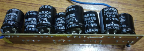
The hardware model of capacitor bank along with the buck boost converter is shown in Figure 3.
Figure 3. Capacitor bank hardware model
The internal circuit diagram of capacitor bank with the connection of diodes is shown in Figure 4. Capacitor bank is a crucial hardware block which is included in our proposed system with a motive to increase the battery capacity by reducing the various parameters like charging current, charging time, discharging current drawn from the battery.
The battery undergoes a sustained discharge current under various load conditions. Specifically, during the peak current experiment, the average current is maintained at 19 Amperes. To achieve this average current draw, we examine five distinct load profiles.
Figure 4. Connection circuituty of capacitor bank
We evaluate the performance of the proposed prototype [19-21] by incorporating a capacitor bank (220µF, 450V series-parallel configuration) in conjunction with the battery, as illustrated in Figure 5. The battery capacity under varying load-conditions is investigated for following factors:
Figure 5. Experimental setup of the system
The different load profiles are denoted as $(D+n)$, where '$D$' represents the driver, and '$n$' signifies the number of passengers occupying the E-Rickshaw [11, 22]. Different load conditions mimic real-world scenarios and help us assess how the ERickshaw performs under various operational circumstances.
To comprehensively assess the impact of the capacitor bank in the proposed hardware prototype model, we have compiled data in Table 2, which includes the maximum starting current values for both scenarios: with and without the implementation of the capacitor bank. Additionally, Table 3 and Table 4 present data depicting the variations in accelerator throttle load and fluctuations in discharging current during operational conditions for all load profiles. These tables offer a comparative analysis of the performance with and without the inclusion of the capacitor bank.
The experimental validation, conducted using a DC power analyzer, confirms that the inclusion of the capacitor bank leads to a consistent reduction in the starting current across all load conditions. This reduction is graphically illustrated in Table 2 using bar graphs.
Table 2. Starting current with and without capacitor bank
Table 3 presents the accelerator throttle load values for various load conditions, comparing our proposed prototype with the conventional type. During extensive testing over approximately five hours, the driver operating the proposed prototype reported a noticeable reduction in accelerator throttle load when the capacitor bank was utilized. This reduction significantly contributed to a smoother and more enjoyable driving experience.
Table 3. Load in accelerator throttle with and without capacitor bank experienced by driver
|
S.No. |
Loading Type (D + 0, 1, 2, 3, 4) D=Driver |
Load in accelerator throttle without capacitor |
Load in accelerator throttle with capacitor |
|
1 |
D+0 |
Normal |
Normal |
|
2 |
D+1 |
Low |
Normal |
|
3 |
D+2 |
Medium |
Low |
|
4 |
D+3 |
Heavy |
Moderate |
|
5 |
D+4 |
Extra Heavy |
Moderate |
Table 3 provides empirical evidence of a reduction in the fluctuation range of discharge current across all load conditions when the capacitor bank is integrated. These fluctuation values are recorded during the vehicle's operation, further demonstrating the capacitor bank's stabilizing effect.
Table 4. Fluctuation in discharging current with and without capacitor bank (Running condition)
|
S.No. |
Loading Type (D + 0, 1, 2, 3, 4) D=Driver |
Discharging current Fluctuation Range without capacitor (Running condition) Amp |
Discharging current Fluctuation Range with capacitor (Running condition) Amp |
|
1 |
D+0 |
2-25 |
2-14 |
|
2 |
D+1 |
4-16 |
4-11 |
|
3 |
D+2 |
5-22 |
5-14 |
|
4 |
D+3 |
8-24 |
6-17 |
|
5 |
D+4 |
11-29 |
9-19 |
The discharging current of the battery with different load profiles is measured through a DC analyser and the plots are shown in Figures 6-10. The observation is quite evident: the introduction of a capacitor bank in tandem with diodes leads to a significant reduction in the fluctuations within the discharge current of the battery. This effect is particularly notable when assessing the impact of varying duty cycles on the battery's capacity.
In systems subjected to duty-cycled loads, where the demand on the battery fluctuates periodically, the capacitor bank plays a pivotal role in stabilizing the load current. As loads vary in intensity over time, the capacitor bank efficiently smooths out these fluctuations, ensuring a more consistent discharge current from the battery. This reduction in discharge current fluctuations is of paramount importance for several reasons. Firstly, it enhances the overall stability of the electrical system, minimizing sudden spikes or dips in power that could affect the performance of the electric vehicle. Secondly, it contributes to improved battery management, extending the battery's lifespan by reducing stress on its components. Furthermore, this observation underscores the capacitor bank's adaptability to varying duty cycles, making it a valuable component in applications where load patterns are subject to periodic changes. In essence, the capacitor bank, when used in conjunction with diodes, not only optimizes the performance of the electrical system but also enhances its resilience in dynamic and variable operating conditions. This finding holds significance for applications ranging from electric vehicles to renewable energy systems, where the stability of power delivery and battery health are paramount. The battery is subjected to a continuous discharge current in the discharge rate experiment. In the maximum discharge current experiment, the average current drawn is set to 29 A and five different load profiles are used to obtain that average current. The load profiles in the period experiment are on/off wave-like fixed duty cycle (50%) and fixed on-current (2A), but with a varied period.
Figure 6. Discharging current with load D+0
Thus, studying the discharging current with varying load conditions of an E-Rickshaw equipped with a Capacitor Bank is vital for evaluating the system's performance, battery health, and the impact of the capacitor on ride quality [23]. It's a key aspect of assessing the practicality and efficiency of such modifications in real-world urban transportation scenarios.
Figure 7. Discharging current with load D+1
Figure 8. Discharging current with load D+2
Figure 9. Discharging current with load D+3
Figure 10. Discharging current with load D+4
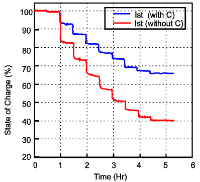
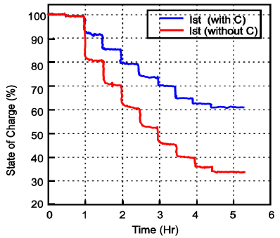
State of Charge (SOC) plays a pivotal role in effectively managing electric vehicles and ensuring their power delivery remains stable even when operating conditions fluctuate. In practical automotive scenarios, accurately quantifying the lithium content within an electrode is a complex task. Instead, SOC must be determined through real-time assessments of voltage, current, and temperature.
SOC serves as a crucial indicator, offering insight into the battery's current condition, and facilitating the safe and optimized charging and discharging processes to extend the battery's lifespan.
Table 5. SOC of Battery with and without capacitor bank (Running condition)
|
Loading Type (D + 0 ,1,2,3,4) D= Driver |
|
|
|
% SOC improve ment of Battery |
|
D+0 |
00 |
70<SOC <75% |
45<SOC <50% |
36.9% |
|
D+1 |
00 |
65<SOC <70% |
45<SOC <50% |
40% |
|
D+2 |
00 |
60<SOC <65% |
30<SOC <35% |
46.7% |
|
D+3 |
00 |
55<SOC <60% |
25<SOC <30% |
50% |
|
D+4 |
00 |
50<SOC <55% |
SOC<25% |
53.8% |
In Table 5, we observe a significant enhancement in the State of Charge (SOC) of the battery over a total runtime of 5.5 hours, with and without the use of a capacitor bank, as the load profile varies. When the capacitor bank is employed, there is a remarkable improvement in the SOC compared to scenarios where it is not utilized. This improvement underscores the positive impact of integrating a capacitor bank in stabilizing and optimizing the battery's SOC across different load profiles.
Figures 11, 12, 13 and 14 depict the State of Charge (SOC) of the system as it evolves over time while the proposed model is subjected to various load conditions. These figures provide a show how the SOC changes in response to different loads, both with and without the incorporation of a capacitor bank.
Figure 11. SOC of battery for load D+0
Figure 12. SOC of battery for load D+1
Figure 13. SOC of battery for load D+2
Figure 14. SOC of battery for load D+3
The employed drain current refers to the rate at which electric current is drawn from the battery during the operation of the E-Rickshaw. In this study, the drain current used is significantly higher, specifically two orders of magnitude larger, than the current specified in the battery datasheet. The battery datasheet specifies a current of 0.2 mA, and the battery's rated capacity is indicated as 240 mAh at this current. Due to the extremely high drain current, the effective capacity of the battery is drastically reduced. The battery might discharge rapidly, and its voltage may drop more quickly than expected. This can affect the overall performance of the E- Rickshaw and could potentially lead to reduced operational range and a shorter battery lifespan.
At the current drain levels utilized in this study, the battery capacity is significantly lower, approximately two orders of magnitude smaller than its rated capacity, measuring around 5mAh. To bolster the study's findings, additional experiments should be conducted at discharge currents more commonly encountered in practical applications.
Figures 8, 9, and 10 provide insights into how each of the three examined factors impacts battery capacity. Notably, the discharge rate exerts the most substantial influence and is a well-established phenomenon. A lower peak current corresponds to a higher effective battery capacity, with this effect being particularly pronounced at lower drain currents.
In this study, we conducted simulations to analyze the behaviour of the battery under various load scenarios. We focused on assessing key parameters such as starting current, accelerator throttle load, and fluctuations in discharge current across these different load modes. The objective was to comprehensively evaluate the performance of our proposed system, which incorporates a capacitor bank, and compare it with conventional systems.
The results obtained from our simulations unequivocally demonstrate the advantages of our proposed system. Even when subjected to heavy load conditions, our system exhibited a significant reduction in the starting current. This reduction not only contributes to smoother driving experiences but also indicates an improved power delivery efficiency.
Furthermore, our findings suggest that the inclusion of a capacitor bank in our hardware model has led to enhancements across all evaluated parameters. This indicates that our system, with the capacitor bank as a critical component, performs notably better than conventional systems in terms of starting current reduction, throttle load optimization, and minimizing discharge current fluctuations.
As the e-rickshaws typically rely on batteries for power, incorporating the capacitors serve the purpose of buffer power delivery to the motor. This potentially reduces the stress on the battery, resulting in longer battery life extends to more than double & hence the system with capacitor has twice the life time.
In summary, our study showcases the superior performance of our proposed hardware model, highlighting the positive impact of the capacitor bank on various crucial parameters. This research contributes valuable insights into the optimization of electric vehicle systems, particularly in the context of E-Rickshaws, ultimately leading to enhanced efficiency and a more pleasant driving experience.
[1] Rana, S., Hossain, F., Roy, S. S., & Mitra, S. K. (2013). The role of battery operated auto-rickshaw in the transportation system of a city. Journal of Asian Electric Vehicles, 11(1), 1635-1644. https://doi.org/10.4130/jaev.11.1635
[2] Xu, J., Qin, Y., Xiao, D., Li, R., & Zhang, H. (2023). The impact of industrial land mismatch on carbon emissions in resource-based cities under environmental regulatory constraints—evidence from China. Environmental Science and Pollution Research, 1-13. https://doi.org/10.1007/s11356-023-29458-w
[3] S.M. Lukic, P. Mulhall, and A. Emadi, “Energy autonomoussolar/battery auto rickshaw,” J. Asian Elect.Vehicles, vol. 6, no. 2, pp.1135–1143, Dec. 2008. https://doi.org/10.4130/jaev.6.1135
[4] Kawamura Naotaka, MutaMitsuharu. Development of Solar Charging System for Plug-in Hybrid Electric Vehicles and Electric Vehicles. In: IEEE International Conference on Renewable Energy Research and Applications (ICRERA), 11-14 Nov. 2012,IEEE, Nagasaki, Japan. https://doi.org/10.1109/ICRERA.2012.6477383
[5] Saurabh, K., & Majumdar, R. (2023). Functional Use- Based Positioning of Conventional Vehicles in Conjunction with Alternate Low-Emission Fuels. In Renewable Fuels for Sustainable Mobility (pp. 97-159). Singapore: Springer Nature Singapore. https://doi.org/10.1007/978-981-99-1392-3_5
[6] Rautela, R., Yadav, B. R., & Kumar, S. (2023). A review on technologies for recovery of metals from waste lithium-ion batteries. Journal of Power Sources, 580, 233428. https://doi.org/10.1016/j.jpowsour.2023.233428
[7] Sun, D., Kyere, F., Sampene, A. K., Asante, D., & Kumah, N. Y. G. (2023). An investigation on the role of electric vehicles in alleviating environmental pollution: evidence from five leading economies. Environmental Science and Pollution Research, 30(7), 18244-18259. https://doi.org/10.1007/s11356-022-23386-x
[8] Bansal, P., Gadepalli, R., & AitBihi Ouali, L. (2023). Eliciting mobility preferences of Indians for E-rickshaws: Evidence from Gurugram. Transport policy, 134, 19-30. https://doi.org/10.1016/j.tranpol.2023.02.006
[9] Rohit, A. K., & Rangnekar, S. (2017). An overview of energy storage and its importance in Indian renewable energy sector: Part II–energy storage applications, benefits and market potential. Journal of Energy Storage, 13, 447-456. https://doi.org/10.1016/j.est.2017.07.012
[10] Jaganath, M. M., Ray, S., & Choudhury, N. D. (2023). Eco-Friendly Microgrid Carport Charging Station for Electric Vehicles (EVs). e-Prime-Advances in Electrical Engineering, Electronics and Energy, 100196. https://doi.org/10.1016/j.prime.2023.100196
[11] Akhtar, M. F., Raihan, S. R. S., Rahim, N. A., Akhtar, M. N., & Abu Bakar, E. (2023). Recent developments in DC- DC converter topologies for light electric vehicle charging: a critical review. Applied Sciences, 13(3), 1676. https://doi.org/10.3390/app13031676
[12] Zhou, K., Wu, Y., Wu, X., Sun, Y., Teng, D., & Liu, Y. (2023). Research and Development Review of Power Converter Topologies and Control Technology for Electric Vehicle Fast-Charging Systems. Electronics, 12(7), 1581. https://doi.org/10.3390/electronics12071581
[13] Yong Jiang, Mahesh Krishnamurthy, “Performance evaluation of ac machines for propulsion in a range extended electric auto rickshaw, ”IEEE Transportation Electrification Conference and Expo (ITEC), , 18-20 June 2012. https://doi.org/10.1109/ITEC.2012.6243486
[14] Mohammed, A. S., Salau, A. O., Sigweni, B., & Zungeru, A. M. (2023). Conversion and performance evaluation of petrol engine to electric powered three-wheeler vehicle with an on board solar charging system. Energy Conversion and Management: X, 20, 100427. https://doi.org/10.1016/j.ecmx.2023.100427
[15] Khan, M. S., & Agrawal, A. (2023, June). Rooftop Solar PV Assisted E-Rickshaw with Hybrid Energy Storage System. In 2023 5th International Conference on Energy, Power and Environment: Towards Flexible Green Energy Technologies (ICEPE) (pp. 1-6). IEEE. https://doi.org/10.1109/ICEPE57949.2023.10201627
[16] Shaha Necolus, Uddin Md. Bashir.Hybrid Energy Assisted Electric Auto Rickshaw Three-Wheeler.In: International Conference on Electrical Information and Communication Technology (EICT), 13-15 Feb. 2014, Khulna, Bangladesh. https://doi.org/10.1109/EICT.2014.6777820
[17] Vignesh, R., Ashok, B., Kumar, M. S., Szpica, D., Harikrishnan, A., & Josh, H. (2023). Adaptive neuro fuzzy inference system-based energy management controller for optimal battery charge sustaining in biofuel powered non-plugin hybrid electric vehicle. Sustainable Energy Technologies and Assessments, 59, 103379. https://doi.org/10.1016/j.seta.2023.103379
[18] Shylla, D., Harikrishnan, R., & Swarnkar, R. (2023). Comparative Analysis and Evaluation of the Different Active Cell Balancing Topologies in Lithium Ions Batteries. Journal of the Electrochemical Society, 170(8), 080501. https://doi.org/10.1149/1945-7111/ace958
[19] Masood Bilal, NaqviRizwan Ali, AsifRao M. Designing of a control scheme for the Solar Rickshaw in Comparative Study with Conventional Auto Rickshaw, 4th International Conference on Engineering Technology and Technopreneuship (ICE2T), 27-29 Aug. 2014,IEEE, Kuala Lumpur, Malaysia,pp.324-329. https://doi.org/10.1109/ICE2T.2014.7006271
[20] Kazmierkowski, M. P. (2010). Electric power systems (review of" Modern Electric, Hybrid Electric, and Fuel Cell Vehicles: Fundamentals, Theory, and Design, ; Ehsani, YG and Emadi, A.; 2010)[Book News]. IEEE Industrial Electronics Magazine, 4(1), 75-75. https://doi.org/10.1109/MIE.2010.936103
[21] Waseem, M., Sherwani, A. F., & Suhaib, M. (2019). Integration of solar energy in electrical, hybrid, autonomous vehicles: a technological review. SN Applied Sciences, 1, 1-14. https://doi.org/10.1007/s42452-019-1458-4
[22] Mulhall, P., Lukic, S. M., Wirasingha, S. G., Lee, Y. J., & Emadi, A. (2010). Solar-assisted electric auto rickshaw three-wheeler. IEEE transactions on vehicular technology, 59(5), 2298-2307.. https://doi.org/10.1109/TVT.2010.2045138
[23] Kavin R, Kesavan T, Dr.Sheebarani S, Gnanamalar, Ramesh kumar Optimal Charging and Discharging Planning for Electric vehicles in Energy saving system. In: International Conference on Advanced Computing & Communication Systems (ICACCS),15-16 March 2019, IEEE, Coimbatore, India,pp.976-978. https://doi.org/10.1109/ICACCS.2019.8728477