Lina Daoudi*![]() | Amel Ourici
| Amel Ourici![]() | Sihem Ghoudelbourk
| Sihem Ghoudelbourk![]()
© 2025 The authors. This article is published by IIETA and is licensed under the CC BY 4.0 license (http://creativecommons.org/licenses/by/4.0/).
OPEN ACCESS
This article proposes a flatness-based control for a renewable hybrid microgrid comprising a photovoltaic (PV), wind turbine (WT), and battery storage systems. The flatness approach generates reference trajectories for DC-link energy voltage regulation and coordinated power sharing. To increase robustness under renewable intermittency and improve reference-trajectory tracking, the proposed control law is augmented by incorporating a predictive neural network (PNN). In addition, a Fuzzy-PI controller is used in the inner converter loops, where fuzzy logic adaptively tunes the PI parameters in real-time based on the error and its variation. A maximum power point tracking (MPPT) technique based on a perturb and observe (PO) was used to maximize the PV’s power. The proposed system was tested in a simulation environment based on MATLAB/Simulink. The obtained results show that the proposed strategy ensures efficient energy management in hybrid microgrids, decreases perturbations in the regulated DC bus, and improves robustness against load variation uncertainties.
control, energy management, photovoltaic, WT, neural network, flatness-based control, battery
The global energy transition to renewable energy resources has risen significantly in the last few years, propelled by the pressing need to reduce greenhouse gas emissions and reliance on fossil fuels, which have limited reserves and cause pollution. Photovoltaic (PV), wind turbine (WT) and water turbine systems are the most deployed renewable technologies, due to their ecological sustainability, economic effectiveness, and modularity. However, their intermittent nature and dependence on meteorological conditions present significant challenges to ensure stability, reliability, and efficient energy utilization in power systems. To address these issues, hybrid renewable energy systems (HRES) are an attractive solution, as they integrate several power sources managed using power electronics converters [1]. A combination of PV, WT, and battery energy storage systems (BESS) have garnered increasing attention as a good solution for the two operational modes of microgrid: isolated mode and grid-connected. In these systems, the battery is essential for balancing generation and demand, mitigating renewable variability and regulating the DC-link voltage [2, 3].
Despite their advantages, the operation and management of hybrid microgrids remain challenging. Advanced control strategies are essential due to the nonlinear dynamics of power converters, the fast fluctuations in renewable energy sources, and the uncertain changes in load. Traditionally, proportional-integral (PI) controllers have been frequently used in the regulation of microgrid converters because of their simplicity and ease of installation [4]. Nevertheless, their limitations have been emphasized in numerous studies when operating in dynamic conditions. For example, Ali et al. [5] found that PI controllers have longer settling periods and undershoot compared to Model Predictive Control (MPC). In general, PI regulators have a fixed-gain structure that renders them susceptible to parameter variations and external disturbances, which can restrict their robustness in microgrids with significant renewable integration [6]. To overcome these shortcomings, several studies have investigated intelligent control strategies. Among them, fuzzy logic controllers (FLCs), which were initially proposed in 1975 [7], are appealing because of their capacity and ability to manage uncertainties while avoiding the need for precise system modeling. In particular, fuzzy-PI schemes combine a traditional PI regulator with the flexibility of fuzzy inference, enabling real-time adjustment of gains [8]. Recent research demonstrates that fuzzy-PI regulators enhance the robustness and convergence of renewable energy systems [9, 10].
In addition to local regulation, predictive control approaches have become more significant for the supervisory control of nonlinear systems. In particular, MPC is extensively utilized in microgrids, providing optimization and improved performance over a finite horizon compared to traditional strategies [11]. However, the computational complexity of MPC frequently restricts its application in real-time scenarios [12]. Another option is predictive neural networks (PNNs), which use the approximation abilities of a multilayer perceptron to predict future trajectories and learn system dynamics. PNN functions as an anticipatory indicator of DC-link energy, offering real-time adjustments for deviations, thereby improving the robustness of supervisory control strategies [13, 14].
In modern control theory, differential flatness, first introduced by Fliess et al. [15], is another efficient and robust framework that provides explicit reference generation for nonlinear systems. It has been successfully applied across various engineering disciplines, including electric vehicle, robotic control, power electronic systems, etc. [16, 17]. Differential flatness is used in hybrid microgrids to generate clear reference trajectories and facilitate coordinated operation, especially for energy balancing and hierarchical control [18]. In practical applications, inner converter loops are frequently regulated using PI controllers, while the integration of predictive and intelligent controllers within the flatness framework can further enhance robustness and dynamic performance under uncertainties.
In this study, an efficient energy management system is proposed based on flatness non-linear control theory hybridized with a PNN control for a microgrid comprising photovoltaic, WT, and battery systems. To enhance robustness and dynamic adaptability, fuzzy-PI controllers are used in the inner loops. This combination of strategies provides a resilient architecture that improves transient response, reduces overshoot, and enhances power sharing between the load, renewable energy sources, and energy storage systems.
The remainder of the paper is structured as follows: Section 2 describes the structure of the hybrid system considered in this study. Section 3 highlights the suggested efficient energy management strategy. Section 4 provides the simulation results and their discussion. Finally, Section 5 presents the conclusion of the paper.
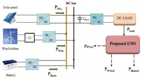
The studied DC microgrid consists of three renewable energy sources: a photovoltaic array, a WT, and a battery energy storage system, as illustrated in Figure 1. Each source is connected in parallel to the common DC bus through dedicated power converters: a DC/DC boost converter for the PV array, a rectifier and DC/DC stage for the WT, and a buck boost DC/DC converter for the battery. The output inverter is linked to the user load through an AC bus (if required for grid-tied systems or to supply AC applications). New techniques are employed in certain papers to minimize the total harmonic distortion of various converters [19-22].
Figure 1. The suggested hybrid system configuration
The photovoltaic source and WT provide the necessary power to satisfy the load demand: it stores surplus energy when renewable generation exceeds consumption, and supplies power during renewable intermittency, thereby maintaining the energy balance of the microgrid [23]. All the sources inject their power into a common DC link that provides the load.
The converters interfacing the renewable generation units and the battery energy storage system are primarily controlled by inner current regulation loops, which are classically employed to guarantee safe operation and fast dynamic response. It is generally assumed that the inner current loop dynamics are significantly faster than those of the outer control layers [24].
3.1 Principle of flatness control approach
The differential flatness can be used to control nonlinear dynamic systems. A system is defined to be flat if there exists a flat output that can be employed to express all the system states and control variables as functions of this output and its derivatives [25, 26]. Mathematically, for a nonlinear system described by Eq. (1):
$\dot{x}=f(x, u)$ (1)
The flatness theory reduces the order model and can be expressed as follows:
$y=\phi\left(x, u, \dot{u}, \ldots, u^{(\alpha)}\right)$ (2)
$\left\{\begin{array}{c}x=\varphi\left(y, \dot{y}, \ldots, y^{(\beta)}\right) \\ u=\psi\left(y, \dot{y}, \ldots, y^{(\beta+1)}\right)\end{array}\right.$ (3)
where, x denotes the state variables, y is the flat output, and u is the control input variable. With the functions of the smooth mappings $\phi, \varphi$ and $\psi$. The term $\mathrm{y}^{(\beta+1)}$ represents the derivative of the output $(\beta+{1})^{\text {th }}, \alpha$ is a finite number of the derivative, and rank $(\phi)=\mathrm{m}, \operatorname{rank}(\varphi)=\mathrm{n}$, and $\operatorname{rank}(\psi)=\mathrm{m}$ [27]. The main advantage of this method is that the system trajectories can be determined and estimated by the flat output and its derivatives. This characteristic makes the flatness approach attractive for nonlinear and hybrid systems [28, 29].
3.2 Mathematical modeling of the hybrid system
For the hybrid power system under study, the PV, WT, and battery currents are assumed to follow their respective reference signals with negligible error. Accordingly, the reference currents are given by the following Eqs. (4), (5), and (6):
$I_{P V}=I_{P V r e f}=\frac{P_{P V}}{V_{P V}}=\frac{P_{P V r e f}}{V_{P V}}$ (4)
$I_{W T}=I_{W T r e f}=\frac{P_{W T}}{V_{W T}}=\frac{P_{W T r e f}}{V_{W T}}$ (5)
$I_{\text {Batt }}=I_{\text {Battref }}=\frac{P_{\text {Batt }}}{V_{\text {Batt }}}=\frac{P_{\text {Battref }}}{V_{\text {Batt }}}$ (6)
where, PPV, and PWT represent the PV and wind generated power, respectively, while PBatt denotes the battery power. VPV, VWT, VBatt and IPV, IWT, IBatt are the voltage and current of the hybrid system respectively. In this study, only static losses are considered in converter models, where rpv, rwt, and rbatt correspond to the static loss parameters of the PV, WT, and battery converters, respectively.
The capacitive energy for both the DC bus and the battery bank can be expressed, according to the study by Thounthong et al. [30], by:
$Y_{B u s}=\frac{1}{2} C_{B u s} \times V_{B u s}^2$ (7)
$Y_{\text {Batt }}=\frac{1}{2} C_{\text {Batt }} \times V_{\text {Batt }}^2$ (8)
where, CBus is the capacitance of the DC bus, CBatt the battery capacitance, VBus is the DC bus voltage and VBatt is the instantaneous voltage of the battery.
The total electrostatic energy YTot stored in the DC-link capacitor CBus and in the battery CBatt can also be written as below:
The capacitive energy for both the DC bus and the battery bank can be expressed by:
$Y_{\text {Tot }}=\frac{1}{2} C_{\text {Bus }} \times V_{\text {Bus }}^2+\frac{1}{2} C_{\text {Batt }} \times V_{\text {Batt }}^2$ (9)
As portrayed in Figure 1, the derivative of DC-bus capacitive energy is defined using PPVo, PWTo, PBatto, and Pload by the following differential Eq. (10):
$\dot{\mathrm{Y}}_{\text {Bus }}=P_{\text {Pvo }}+P_{\text {WTo }}+P_{\text {Batto }}-P_{\text {load }}$ (10)
where,
$P_{P v o}=P_{P V}-r_{p v} \times\left(\frac{P_{P V}}{V_{P V}}\right)^2$ (11)
$P_{W t o}=P_{W T}-r_{w t} \times\left(\frac{P_{W T}}{V_{W T}}\right)^2$ (12)
$P_{\text {Batto }}=P_{\text {Batt }}-r_{\text {batt }} \times\left(\frac{P_{\text {Batt }}}{V_{\text {Batt }}}\right)^2$ (13)
The power demanded by the load is defined as:
$P_{\text {load }}=V_{\text {Bus }} \times I_{\text {load }}=\sqrt{\frac{2 Y_{\text {Bus }}}{C_{\text {Bus }}}} . I_{\text {load }}$ (14)
3.3 Flatness of the power system model
To verify the flatness property [31], the system introduced above is analyzed. According to the flatness theory, the flat outputs Y, the control input variables u, and the state variables x are expressed as follows:
$Y=\left[\begin{array}{l}Y_{\text {Bus }} \\ Y_{\text {Tot }}\end{array}\right]=\left[\begin{array}{l}Y_1 \\ Y_2\end{array}\right]$ (15)
$u=\left[\begin{array}{c}P_{\text {Batt }} \\ P_{\text {PVdemd }}\end{array}\right]=\left[\begin{array}{l}u_1 \\ u_2\end{array}\right]$ (16)
$x=\left[\begin{array}{c}V_{\text {Bus }} \\ V_{\text {Batt }}\end{array}\right]=\left[\begin{array}{l}x_1 \\ x_2\end{array}\right]$ (17)
where, we assume that the photovoltaic (PV) is the principal and the first primary source for the hybrid proposed PV-WT-Battery power system, and PPVdemd is the required power of the differential flatness control algorithm.
The electrostatic energy YBus of the DC bus of the system is assumed constant and defined as a flat output Y1, and can be written as:
$\dot{\mathrm{Y}}_{\text {Bus }}=0=P_{\text {Pvo }}+P_{W T o}+P_{\text {Batto }}-P_{\text {load }}$ (18)
Also, the electrostatic energy YBus is constant and represented as a flat output Y2. Therefore:
$\dot{\mathrm{Y}}_2=0=P_{P v o}+P_{W T o}-P_{l o a d}$ (19)
It is stocked in the DC bus capacitor CBus and in the battery bank.
The stat variables (x1, x2) of DC link voltage and the battery voltage respectively, can be written as:
$x_1=V_{B u s}=\sqrt{\frac{2 \times Y_{B u s}}{C_{B u s}}}=\varphi_1\left(Y_1\right)$ (20)
$x_2=V_{\text {Batt }}=\sqrt{\frac{2\left(Y_{\text {tot }}-Y_{\text {Bus }}\right)}{C_{\text {Batt }}}}=\varphi_2\left(Y_1, Y_2\right)$ (21)
From (10) to (14), the input control variables u can be calculated from the flat outputs Y and their time derivatives:
$u_1 = 2 \cdot P_{\text{BattLim}} \left[ 1 - \sqrt{ 1 - \left( \frac{\dot{Y}_1 + I_{\text{load}} \times \varphi_1(Y_1) - P_{Pvo} - P_{WTo}} {P_{\text{BattLim}}} \right) } \right]$ (22)
$u_1=\psi\left(Y_1, \dot{Y}_1\right)=P_{\text {Battref }}$ (23)
$u_2 = 2 \cdot P_{\text{totLim}} \left[ 1 - \sqrt{ 1 - \left( \frac{\dot{Y}_2 + I_{\text{load}} \times \varphi(Y_1)} {P_{\text{totLim}}} \right) } \right] = \psi_2(Y_1, \dot{Y}_2)$ (24)
where,
$P_{\text {BattLim }}=\frac{V_{\text {Batt }}^2}{4 r_{\text {batt }}}$ (25)
$P_{\text {totLim }}=P_{\text {PVLim }}+P_{\text {WTLim }}$ (26)
PBattLim is the limited maximum power from the battery buck-boost converter.
Therefore, and according to the preceding design, the proposed reduced order-model can be considered as a flat system [32].
3.4 The control law
The control loop of the battery energy depends on the regulation of the total electromagnetic energy. The control law of the battery used in this work can be written as [33]:
$\left(\dot{Y}_2-\dot{Y}_{2 r e f}\right)+K_{21}\left(Y_2-Y_{2 r e f}\right)=0$ (27)
This gives:
$\dot{Y}_2=\dot{Y}_{2 r e f}+K_{21}\left(Y_{2 r e f}-Y_2\right)$ (28)
where, Y2ref is the reference of total electrostatic energy (see Eq. (9)), and K21 represents the control parameter.
3.5 PNN law for DC-Bus energy stabilization
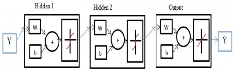
The neural predictor is designed to allow the user some freedom in selecting the inputs/states/outputs variables and adopting a fully connected MLP (Multi-Layer Perceptron) with tanh hidden activations and a linear output. The number of hidden neurons is determined iteratively until the validation error ceases to improve.
Training is based on time-aligned sequences generated from the MATLAB/Simulink: the control inputs used for the plant and the associated measured outputs. The network is thus identified as a forward predictor, trained by minimizing the prediction error so that its output closely matches the plant’s measured response over time.
During operation, the trained neural network is used within a predictive control framework to capture the short-term evolution of the DC-link over a finite prediction horizon. Based on the reference trajectory (for example, from the DC-bus energy set-point), the proposed PNN directly generates the control action at each sampling instant to ensure accurate tracking while limiting excessive control variations. In this way, the predictive objective is preserved without solving an explicit receding-horizon optimization problem, since the control law is obtained through a single forward evaluation of the trained MLP.
In this work, the neural network model uses the DC-link energy as input (along with optional past values and additional signals) to predict the next step output, which corresponds to the power supplied by the DC bus. This predicted power is the representation of the plant’s dynamic response. The training dataset contains this input value and the output target, and was generated from MATLAB/Simulink simulations. The network is trained offline using the Levenberg-Marquardt algorithm (LM), and the performance was evaluated using the mean square error MSE.
The model used to predict the output of the control law is given by the following energy balance equation:
$\dot{\mathrm{Y}}_{\text {Bus }}=0=P_{\text {Pvo }}+P_{W T o}+P_{\text {Batto }}-P_{\text {load }}$ (29)
The neural network is trained to minimize a performance criterion derived from classical predictive control, expressed as:
$\begin{aligned} J=\sum_{j=N_1}^{N_2}\left(Y_{\text {Bus }}(t\right. & \left.+j)-\dot{\mathrm{Y}}_m(t+j)\right)^2 +\rho \sum_{j=1}^{N_2} u(t+j-1)-u(t+j -2))^2\end{aligned}$ (30)
where, N1, N2, and Nu are, respectively, the horizons over which the tracking error and the control increments are computed, YBus is the desired output, Ym is the output predicted by the neural model, and u is the tentative control signal. The parameter ρ adjusts the influence of control increments in the performance index and is selected through a parametric sweep to achieve an appropriate trade-off between tracking accuracy and control smoothness. This function represents the performance objective that the NN implicitly acquires during training. Thus, the suggested PNN controller operates in a feedforward predictive manner, immediately producing the control signal from the neural outputs.
In online operation, the controller only evaluates a forward pass of the trained MLP at each sampling instant (i.e., a limited number of multiply-accumulate operations and activation function evaluations). Therefore, no online optimization is required, that make the proposed approach compatible with real-time implementation on standard digital control platforms.
The topology of the neural network used is presented in Figure 2. A two-hidden-layer feedforward network MLP [5 2] neurons was trained. Where w is the weight and b represents the biases of the neural network layers.
Figure 2. Topology of the proposed neural network model
3.6 Inner current control
In the proposed flatness-based control architecture, the inner control loops of the converters are implemented utilizing a fuzzy PI controller as a replacement for the conventional PI regulator. This hybrid strategy combines the simplicity of the PI controller with the intelligence and adaptability of fuzzy logic to provide the capability of adapting the control effort online (implicit gain scheduling) [34]. Within this architecture, the flatness-based control approach generates the reference trajectories, while fuzzy PI regulator controls the converter output currents and guarantees precise tracking in the inner loops [35]. The objective is to enhance robustness and dynamic efficacy of the internal regulation, especially under load changes, renewable generation fluctuations, and system parameters uncertainties [36].
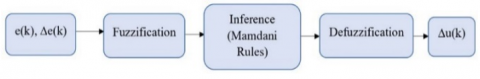
The fuzzy PI controller uses two inputs: the normalized error e(k) and the change in error Δe(k). These crisp inputs are fuzzified using a triangular membership functions with linguistic variables: Negative Big (NB), Negative Medium (NM), Negative Small (NS), Zero (ZE), Positive Small (PS), Positive Medium (PM), and Positive Big (PB). The fuzzy system outputs the incremental control signal Δu(k) from the inputs, which updates the PI control rule. Hence, the controller operates as an adaptive mechanism that implicitly adjusts the equivalent PI action online (implicit gain scheduling). The schematic of the fuzzy PI controller structure is shown in Figure 3.
Figure 3. Fuzzy PI controller structure
The fuzzy rule base is developed by combining control heuristics and expert knowledge, as illustrated in Table 1. Large errors generate strong corrective actions, while small errors near the steady state produce mild control efforts to reduce oscillations. Defuzzification is achieved through the application of the centroid method for enabling smooth actuation.
This method enables faster settling, reduced overshoot, and enhanced rejection of disturbances compared to a fixed PI controller, with better dynamic behavior of the inner loops of the converters in the flatness-based energy management technique.
Table 1. Rule base
|
e / de |
NB |
NM |
NS |
ZE |
PS |
PM |
PB |
|
NB |
NB |
NB |
NB |
NM |
NS |
ZE |
ZE |
|
NM |
NB |
NB |
NM |
NS |
ZE |
ZE |
PS |
|
NS |
NB |
NM |
NS |
ZE |
PS |
PM |
PB |
|
ZE |
NM |
NS |
ZE |
ZE |
ZE |
PS |
PM |
|
PS |
NS |
ZE |
PS |
PM |
PB |
PB |
PB |
|
PM |
ZE |
ZE |
PM |
PB |
PB |
PB |
PB |
|
PB |
ZE |
PS |
PM |
PB |
PB |
PB |
PB |
The suggested control system regulates two main energy-related variables utilizing the PNN control law: the DC bus voltage of the hybrid system and the battery storage energy YBatt.
Figure 4 illustrates the suggested control strategy for the hybrid microgrid. In this configuration, the DC bus energy control law, implemented through the PNN, produces a reference signal corresponding to the DC-link power to be delivered. This reference power is then converted into the battery current reference IBattref by dividing it by the measured battery-bank voltage, as given in Eq. (22).

Figure 4. Structural design control of the proposed hybrid system
The global energy management layer (total energy control) provides the overall power reference PTotref. This reference is assigned to the PV power command PPVref, which is constrained between the minimum value and the maximum available PV power determined by the MPPT algorithm. The remaining power, obtained from the difference between PTotref and PPVref, defines the WT power reference PWTref, thereby ensuring a balanced power distribution among all renewable sources within the hybrid microgrid. Nevertheless, the results of the energy asymptotic control law using Eq. (32) are found to be similar to those when the PNN is utilized.
$\begin{gathered}\left(\dot{Y}_{1 \mathrm{ref}}-\dot{Y}_1\right)+K_1\left(Y_{1 \mathrm{ref}}-Y_1\right)+K_2 \int\left(Y_{1 \mathrm{ref}}-Y_1\right) =0\end{gathered}$ (31)
$\dot{Y}_1=\dot{Y}_{1 \mathrm{ref}}+K_1\left(Y_{1 \mathrm{ref}}-Y_1\right)+K_2 \int\left(Y_{1 \mathrm{ref}}-Y_1\right)$ (32)
The asymptotic flatness feedback is parameterized by the gains K1 and K2, defined as: K1 = 2ζωn and K2 = ωn2, with ζ and ωn denoting the desired dominant damping ratio and natural frequency, respectively. These control parameters (K1, K2) are selected using a second-order dominant dynamics specification. Accordingly, the desired closed-loop characteristic polynomial is chosen as:
$p(s)=s^2+2 \zeta \omega_n s+\omega_n^2$ (33)
In this work, the proposed energy management is evaluated using MATLAB/Simulink. The parameters of the system and of the control loop used in the simulation are summarized in Table 2.
Table 2. Parameters of the system
|
Source |
Parameter |
Value |
Unit |
|
WT source |
Rated power |
400 |
W |
|
Battery |
Nominal voltage |
48 |
V |
|
|
Capacity |
100 |
Ah |
|
PV source |
Power rating |
300 |
W |
|
|
Panel rated voltage |
36.9 |
V |
|
|
Panel rated current |
8.13 |
A |
|
DC bus |
Rated voltage VDCref |
120 |
V |
|
|
CDC |
3000e-6 |
F |
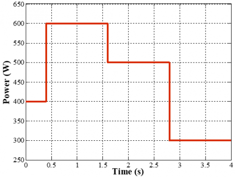
In order to assess and validate the performance of the proposed control strategy, the load power profile shown in Figure 5 is applied over a 5 second simulation interval.
Figure 5. Load profile
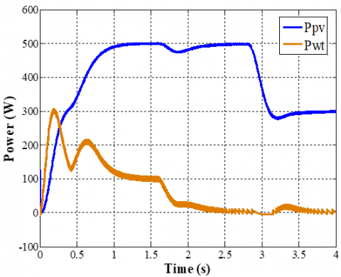
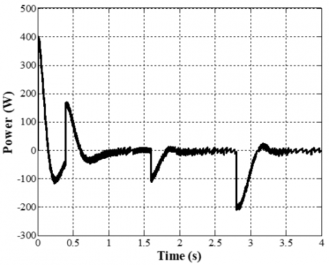
The power simulation generated from different sources of the hybrid system is shown in Figures 6 and 7. As observed, during the initial period from 0-0.3 s, the battery compensates for the power deficit by discharging. Subsequently, the PV system, that acts as the primary source, takes over and starts generating power, while the WT provides auxiliary support and serves as a secondary source. Both renewable sources complement each other to fulfill the load demand, whereas the battery oscillates between charging, when the generation surpasses load demand, and discharging, during transients, to regulate the DC-link power balance. The observed smooth dynamics are also facilitated by the inner loop controller, which ensures robust current regulation for each converter.
Figure 6. Power produced from PV and WT sources
Figure 7. Power produced from the battery bank
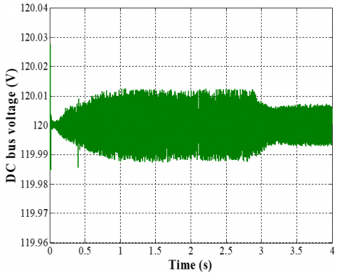
Figures 8-10 demonstrate that the proposed control law utilizing the PNN achieves accurate reference tracking and maintains stable operation. In particular, Figure 8, the DC-bus voltage remains tightly regulated around its reference value of 120 V, with a very small peak deviation (overshoot/undershoot) and a fast transient response (static error of 0.98V = 0.8167%). The steady-state error remains negligible, indicating accurate voltage regulation despite load and generation variations.
Figure 8. DC bus voltage response under the proposed PNN control law
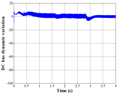
Figure 9. Variation of the DC bus link
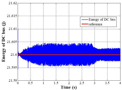
Figure 10. The DC bus energy and reference trajectory
Figure 10 illustrates the dynamic variation of the DC bus (NN output). This signal demonstrates minimal oscillations that indicate a stable and well-damped control action.
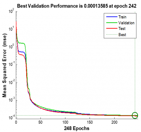
The results of the training performance of the PNN are shown in Figure 11. The mean squared error (MSE) decreases rapidly and reaches a minimum value of 0.00013585 at epoch 242, indicating the model’s strong generalization capacity. The training, validation, and testing curves are close, which indicates that the neural network attained steady convergence without overfitting.
Figure 11. Training performance of the neural network
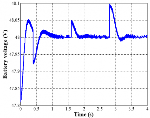
The battery voltage is balanced within the interval of 47.8 V to 48.2 V with a decrease at the time of starting, as depicted in Figure 12. The absence of high-frequency oscillations validates the reliable performance of the buck-boost converter, which is controlled by the fuzzy pi regulator and guarantees stable voltage regulation.
Figure 12. Voltage of the battery
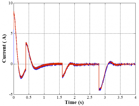
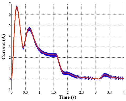
According to Figures 13 and 14, both the currents of the battery and WT exhibit excellent reference tracking, with negligible steady-error and no noticeable oscillations (low overshoot), which confirms the effectiveness of the inner current regulation loops.
Figure 13. The battery current and its reference
Figure 14. The WT current and its reference
This paper presents a flatness-based control method for a hybrid photovoltaic/wind turbine/battery direct current microgrid using the PNN control law to improve trajectory tracking and address nonlinearities and model uncertainties. The PNN makes the system more resilient and responsive by comprehending the forward dynamics of the DC bus and ensuring more accurate reference tracking for diverse loads with a lower static error. A fuzzy-PI regulation method was employed at the converter level to replace the conventional PI controllers in the inner current loops. MATLAB/Simulink was used to design and simulate the proposed control strategy. The simulation results indicate that this technique ensures stable DC bus regulation with minimized overshoot (0.05%) and seamless power distribution among sources. The research illustrates the capacity of integrating the differential flatness approach with intelligent control strategies for enhanced energy management in DC microgrids.
For completeness and contextualize the proposed contribution relative to commonly adopted PI and MPC strategies, Table 3 summarizes a qualitative comparison relying on commonly reported characteristics in the literature and the behavior observed in the simulation results reported in this paper.
Several directions are suggested for future research to extend this study: 1) include experimental validation; 2) the incorporation of supplementary optimization layers (such as economic dispatch); and 3) design and control of a hybrid DC/AC microgrid configurations.
Table 3. Qualitative comparison with classical PI and MPC controllers
|
Criterion |
Classical PI (literature) |
MPC (literature) |
Proposed Control |
|
Tracking under disturbance |
Medium |
High |
High (see Figures 8-10, 13-14) |
|
Overshoot/oscillations |
Medium |
Low-Medium |
Low (well-damped in results) |
|
Steady-state error |
Moderate |
Low |
Low/negligible (observed) |
|
Constraint handling |
Low-Moderate |
High |
Limited |
|
PV |
photovoltaic |
|
WT |
wind turbine |
|
PNN |
predictive neural network |
|
MPPT |
maximum power point tracking |
|
PO |
perturb and observe |
|
HRES |
hybrid renewable energy systems |
|
BESS |
battery energy storage systems |
|
PI |
proportional integral |
|
MPC |
model predictive control |
|
FLC |
fuzzy logic controllers |
|
MLP |
model predictive control |
[1] Das, S., Maitra, S.K., Thrinath, B.S., Choudhury, U., Swathi, G.V., Datta, G. (2024). An effective sizing study on PV-wind-battery hybrid renewable energy systems. e-Prime-Advances in Electrical Engineering, Electronics and Energy, 10: 100824. https://doi.org/10.1016/j.prime.2024.100824
[2] Bukar, A.L., Tan, C.W. (2019). A review on stand-alone photovoltaic–wind energy system with fuel cell: System optimization and energy management strategy. Journal of Cleaner Production, 221: 73-88. https://doi.org/10.1016/j.jclepro.2019.02.228
[3] Ali, M.F., Sheikh, M.R.I., Akter, R., Islam, K.M.N., Ferdous, A.H.M.I. (2025). Grid-connected hybrid microgrids with PV/wind/battery: Sustainable energy solutions for rural education in Bangladesh. Results in Engineering, 25: 103774. https://doi.org/10.1016/j.rineng.2024.103774
[4] Akarne, Y., Essadki, A., Nasser, T., Annoukoubi, M., Charadi S. (2025). Optimized control of grid-connected photovoltaic systems: Robust PI controller based on sparrow search algorithm for smart microgrid application. Global Energy Interconnection, 8(4): 523-536. https://doi.org/10.1016/j.gloei.2025.05.004
[5] Ali, S.U., Waqar, A., Aamir, M., Qaisar, S.M., Iqbal, J. (2023). Model predictive control of consensus-based energy management system for DC microgrid. PLOS ONE, 18(1): e0278110. https://doi.org/10.1371/journal.pone.0278110
[6] Yang, Z., Wang, C., Han, J., Yang, F., et al. (2023). Analysis of voltage control strategies for DC microgrid with multiple types of energy storage systems. Electronics, 12(7): 1661. https://doi.org/10.3390/electronics12071661
[7] Mamdani, E.H., Assilian, S. (1975). An experiment in linguistic synthesis with a fuzzy logic controller. International Journal of Man-machine Studies, 7(1): 1-13. https://doi.org/10.1016/S0020-7373(75)80002-2
[8] Borase, R.P., Maghade, D.K., Sondka,r S.Y., Pawar, S.N. (2021). A review of PID control, tuning methods and applications. International Journal of Dynamics and Control, 9(2): 818-827. https://doi.org/10.1007/s40435-020-00665-4
[9] Aljohani, T. (2024). Intelligent type-2 fuzzy logic controller for hybrid microgrid energy management with different modes of EVs integration. Energies, 17(12): 2949. https://doi.org/10.3390/en17122949
[10] Mohamed, M.A.E., Ward, S.A., El-Gohary, M.F., Mohamed, M.A. (2025). Hybrid fuzzy logic–PI control with metaheuristic optimization for enhanced performance of high-penetration grid-connected PV systems. Scientific Reports, 15(1): 24650. https://doi.org/10.1038/s41598-025-09336-w
[11] Hu, J., Shan, Y., Guerrero, J.M., Ioinovici, A., Chan, K.W., Rodriguez, J. (2021). Model predictive control of microgrids–An overview. Renewable and Sustainable Energy Reviews, 136: 110422. http://doi.org/10.1016/j.rser.2020.110422
[12] Schwenzer, M., Ay, M., Bergs, T., Abel, D. (2021). Review on model predictive control: An engineering perspective. The International Journal of Advanced Manufacturing Technology, 117(5): 1327-1349. https://doi.org/10.1007/s00170-021-07682-3
[13] Rashid, S.M. (2025). A novel voltage control system based on deep neural networks for microgrids including communication delay as a complex and large-scale system. ISA Transactions, 158: 344-362. https://doi.org/10.1016/j.isatra.2025.01.028
[14] Cheng, Y., Zhang, J., Al Shurafa, M., Liu, D., Zhao, Y., Ding, C., Niu, J. (2025). An improved multiple adaptive neuro fuzzy inference system based on genetic algorithm for energy management system of island microgrid: Y. Cheng et al. Scientific Reports, 15(1): 17988. https://doi.org/10.1038/s41598-025-98665-x
[15] Fliess, M., Levin, J., Martin, Ph., Rouchon, P. (1999). A Lie-Bäcklund approach to equivalence and flatness of nonlinear systems. IEEE Transactions on Automatic Control, 44(5): 922-937. https://doi.org/10.1109/9.771073
[16] Maheswari, L., Sivakumaran, N. (2021). Differential flatness-based strategy of Photovoltaic/Battery/supercapacitor hybrid source for stand-alone system. Materials Today: Proceedings, 46: 10036-10042. https://doi.org/10.1016/j.matpr.2021.06.094
[17] Thounthong, P., Sikkabut, S., Mungporn, P., Sethakul, P., Pierfederici, S., Dava, B. (2013). Differential flatness-based control of fuel cell/photovoltaic/wind turbine/supercapacitor hybrid power plant. In 2013 International Conference on Clean Electrical Power (ICCEP), Alghero, Italy, pp. 298-305. https://doi.org/10.1109/ICCEP.2013.6587005
[18] Zafeiratou, I., Prodan, I., Lefèvre, L., Piétrac, L. (2020). Meshed DC microgrid hierarchical control: A differential flatness approach. Electrical Power Systems Research, 180: 106133. https://doi.org/10.1016/j.epsr.2019.106133
[19] Al-Dmour, A.S., Al-Majali, H.D., Al-Majali, Z.S. (2021). Staircase modulation using GWO technique for CHB-MLI with symmetrical and asymmetrical mode. International Journal of Engineering Trends and Technology, 69(8): 71-80. https://doi.org/10.14445/22315381/IJETT-V69I8P209
[20] Al-Majali, H.D., Al-Majali, B.H., Almajali, Z.S. (2020). Reduced harmonics generated and reactive volt-ampere absorption of HVDC converter using bypass switch. WSEAS Transactions on Systems and Control, 15: 212-217. https://doi.org/10.37394/23203.2020.15.23
[21] Al-Majali H.D., Al-Majali B.H. (2019). Fast and continuous control of a modified HVDC converter. WSEAS Transactions on Systems and Control, 14: 326-333.
[22] Alzahlan, M.W., Alawasa, K.M., Al-Majali, H.D. (2019). Performance evaluation of different optimal-tuned current controllers for voltage-source converter connected to a weak AC grid. In 2019 IEEE Jordan International Joint Conference on Electrical Engineering and Information Technology (JEEIT), Amman, Jordan, pp. 198-203. https://doi.org/10.1109/JEEIT.2019.8717376
[23] Mahjoub, S., Chrifi-Alaoui, L., Drid, S. (2023). Control and implementation of an energy management strategy for a PV–Wind–Battery microgrid based on an intelligent prediction algorithm of energy production. Energies, 16(4): 1883. https://doi.org/10.3390/en16041883
[24] Yaqoob, S.J., Arnoos, H., Qasim, M.A., Agyekum, E.B., Alzahrani, A., Kamel, S. (2023). An optimal energy management strategy for a photovoltaic/Li-ion battery power system for DC microgrid application. Frontiers in Energy Research, 10: 1066231. https://doi.org/10.3389/fenrg.2022.1066231
[25] Aimene M., Payman A., Dakyo B. (2022). Comparative study between flatness‑based and field‑oriented control methods of a grid‑connected wind energy conversion system. Processes, 10(2): 378. https://doi.org/10.3390/pr10020378
[26] Ferahtia, S., Djerioui, A., Zeghlache, S., Houari, A. (2020). A hybrid power system based on fuel cell, photovoltaic source and supercapacitor. SN Applied Sciences, 2(5): 940. https://doi.org/10.1007/s42452-020-2709-0
[27] Abbas, F.A., Obed, A.A., Qasim, M.A., Yaqoob, S.J., Ferahtia S. (2022). An efficient energy management strategy for a DC microgrid powered by PV/FC/Battery/Supercapacitor. Clean Energy, 6(6): 827-839. https://doi.org/10.1093/ce/zkac063
[28] Veeser, F., Braun, T., Kiltz, L., Reuter, J. (2021). Nonlinear modelling, flatness-based current control, and torque ripple compensation for IPMSM. Energies, 14(6): 1590. https://doi.org/10.3390/en14061590
[29] Thounthong, P., Mungporn, P., Guilbert, D., Takorabet, N., et al. (2021). Design and control of multiphase interleaved boost converters-based on differential flatness theory for PEM fuel cell multi-stack applications. International Journal of Electrical Power & Energy Systems, 124: 106346. https://doi.org/10.1016/j.ijepes.2020.106346
[30] Thounthong, P., Tricoli, P., Davat, B. (2014). Performance investigation of linear and nonlinear controls for a fuel cell/supercapacitor hybrid power plant. International Journal of Electrical Power & Energy Systems, 54: 454-464. https://doi.org/10.1016/j.ijepes.2013.07.033
[31] Gensior, A., Nguyen, T.M.P., Rudolph, J., Guldner, H. (2011). Flatness-based loss optimization and control of a doubly fed induction generator system. IEEE Transactions on Control Systems Technology, 19(6): 1457-1466. https://doi.org/10.1109/TCST.2010.2093899
[32] Thounthong, P., Pierfederici, S. (2010). A New control law based on the differential flatness principle for multiphase interleaved DC-DC converter. IEEE Transactions on Circuits and Systems II: Express Briefs, 57(11): 903-907. https://doi.org/10.1109/TCSII.2010.2082830
[33] Hamedani, S., Zandi M. (2016). Flatness-based control method: A review of its applications to power systems. In 2016 7th power Electronics and Drive systems Technologies Conference (PEDSTC), Tehran, Iran, pp. 547-552. https://doi.org/10.1109/PEDSTC.2016.7556919
[34] Ibrahim, W.K., Abdullah, F.S., Ali, F.A. (2025). Comparative analysis of fuzzy logic, PID, and FOPID controllers in DC microgrid voltage regulation for power plants: Integrating renewable energy sources. Journal of Advanced Research in Applied Mechanics, 128(1): 50-61. https://doi.org/10.37934/aram.128.1.5061
[35] Silva-Ortigoza, R., Roldán-Caballero, A., Hernández-Márquez, E., García-Sánchez, J.R., Marciano-Melchor, M., Hernández-Guzmán, V.M., Silva-Ortigoza, G. (2021). Robust flatness tracking control for the “DC/DC Buck converter‑DC motor” system: Renewable energy‑based power supply. Complexity, 2021(1): 2158782. https://doi.org/10.1155/2021/2158782
[36] Nasim, F., Khatoon, S., Ibraheem, Urooj, S., Shahid, M., Ali, A., Nasser, N. (2025). Hybrid ANFIS-PI-based optimization for improved power conversion in DFIG wind turbine. Sustainability, 17(6): 2454. https://doi.org/10.3390/su17062454