Vinod Chandrakant Todkari![]() | Avinash P. Kaldate
| Avinash P. Kaldate![]() | Shrikrishna Kolhar*
| Shrikrishna Kolhar*![]() | Arvind Jagtap
| Arvind Jagtap![]() | Nilesh P. Sable
| Nilesh P. Sable![]()
© 2025 The authors. This article is published by IIETA and is licensed under the CC BY 4.0 license (http://creativecommons.org/licenses/by/4.0/).
OPEN ACCESS
A self-contained guidance system is required in robotics and automation laboratories for autonomous navigation purposes. In laboratory conditions where conditions are constantly changing, regular fixed-path solutions will not work. In this paper, a comprehensive framework for a tour guide robot is developed. An AI-driven visual navigation system is used to guide the robot. Simultaneous localization and mapping (SLAM) is implemented instead of the traditional line following approach. Deep learning-based obstacle detection is optimized for robot path planning. ORB-SLAM2 (monocular version) is considered for real-time localization and mapping. A specific data set is taken from the laboratory for fine-tuning of YOLOv5s for dynamic obstacle detection. The algorithm is extended for real-time path planning to avoid obstacles in the robot’s path. Raspberry Pi 4 and Arduino Uno are used for the development of the embedded system so that it compares both for practical deployment feasibility. In this research, a 40% reduction in tour completion time and a 95% obstacle avoidance success rate are achieved. This investigation has achieved an average path deviation accuracy of 1.1 cm. A sensor fusion architecture is used to combine visual SLAM feature with deep learning detection for robust navigation. This research considers and impacts the architecture contrasts on hardware. Extensive performance characteristics are studied under different environmental conditions. This proposed AI-driven robot navigation in lab operations has set a new benchmark for intelligent robotics in academia and the public sector.
Artificial Intelligence, computer vision, Convolutional Neural Networks, deep learning, dynamic path planning, robotics, visual SLAM
While robotics and automation lab technologies provide a learning platform, the frequent human involvement in guided lab tours highlights technological inefficiencies [1]. Traditionally, line-following robots have been used to guide people. However, these types of robots are resilient to environmental changes. Line-following robots use predefined paths and are not flexible to adapt to environmental changes [2]. These contradictions are a major obstacle to their use in real laboratories. It is difficult to use line-following robots in places where equipment positions change and tourist traffic patterns change frequently [3]. To overcome these challenges, this research uses an AI-driven visual navigation system. The aim of this research is to develop a navigation system for laboratory environments without predefined paths [4]. The architecture is developed by three technologies: visual simultaneous localization and mapping (SLAM) for spatial awareness, deep learning-based object detection for obstacle recognition, and adaptive path planning for intelligent navigation decisions.
ORB-SLAM2 has real-time localization and mapping in its monocular configuration [5]. It provides metric scale environmental perception. In this research, dynamic obstacle detection is performed by YOLOv5s [6]. This YOLOv5 architecture is specifically fine-tuned for laboratory environments. An A* algorithm integrates real-time obstacle information with global path planning in the navigation system [7]. It enables dynamic rerouting in response to environmental changes [8]. This research contributes to a novel sensor fusion framework that combines visual SLAM features with deep learning-based object detection. It creates a unified representation for navigation decision making. The hardware is Raspberry Pi 4 for optimized implementation of computationally intensive algorithms. The Raspberry Pi 4 has achieved real-time implementation through careful system design and optimization. This research provides experimental validation in realistic laboratory settings. Several metrics include navigation performance to characterize system performance. Computational requirements and environmental robustness should be considered in developing the framework.
Section 2 reviews relevant literature on visual SLAM, deep learning for robotics, and path planning algorithms. Section 3 details our system architecture and mathematical framework. Section 4 describes the implementation methodology. Section 5 presents experimental results and analysis. Section 6 concludes with future research directions.
The development of autonomous tour guide robots has evolved significantly over the past decades. Thrun et al. [3] demonstrated the feasibility of autonomous robot navigation in public areas. It has various limitations such as computing resources and sensor technology [9]. This developer system mostly relies on laser range finders and pre-mapped environments. It also has limitations such as limited adaptability and increasing deployment costs. This research considers modern approaches in computer vision and machine learning systems [2]. It offers more flexibility and cost-effective solutions. Visual SLAM as another alternative to traditional sensor-based localization methods [10]. Redmon et al. [6] incorporated the capabilities of the camera insect localization method. ORB-SLAM is a feature-based method that is used to significantly improve and increase computational efficiency [11, 12]. Recent research focusing on real-time performance and robustness in dynamic environments [11]. ORB-SLAM2 has implemented embedded hardware for practical deployment in the laboratory, which I consider to be significantly cost-effective [3]. Recent advancements in visual SLAM for dynamic environments have shown promising results. Bescos et al. [13] introduced an approach for tracking, mapping, and inpainting in dynamic scenes, which is particularly relevant for tour guide robots operating in environments with moving people and objects. Similarly, Yu et al. [14] presented a semantic visual SLAM system that integrates semantic segmentation to better handle dynamic objects. More recently, Zhu et al. [15] proposed a double-constrained visual SLAM approach for realistic map reconstruction in dynamic scenes, offering improved robustness. For navigation in dynamic environments, deep reinforcement learning approaches have shown significant potential [16], though they often require extensive computational resources not suitable for embedded systems like Raspberry Pi [17]. Deep learning has been used for robotic perception. It gives importance to any objective question and visual perception [18]. The evolution has been from traditional computer vision methods to deep learning methods. Architectures like R-CNN have enabled [10]. Redmon et al. [6] has been used for real-time object detection with high accuracy. YOLOv5 has used a balance of speed and accuracy, YOLO is also suitable for real-time robotic applications in which computing resources are limited. Using advanced technologies, robots are able to understand and perceive the environment more effectively.
This research has opened up new possibilities for autonomous navigation in complex situations and dynamic spaces. A grid-based approach has considered path planning algorithms in robotic systems. The A* algorithm [7] contains the fundamental principles for optimal path finding in robotic systems [19]. The real-time dynamic window approach and potential field methods are important aspects of the robot navigation framework against obstacles. These can adapt to changing environmental conditions while maintaining optimal combinations.
3.1 System overview
In this research, SLAM and obstacle detection are performed using a camera as the primary sensor. Raspberry Pi is used as the main processing unit in this embedded system. In the research, localization and mapping are performed with the help of ORB-SLAM2. Planning and object detection are performed using YOLOv5. Raspberry Pi handles the high-level navigation commands and is implemented by Arduino along with motor control. It has a hierarchical control structure in which high-level decision making is implemented by the low level activation system.
3.2 Robot kinematics
Different configurations are commonly used in mobile robotics. This given kinematic model provides a robust underlying mathematical model for motion control and path following. The robot’s pose in the world coordinate system is represented by $q=[x, y, \theta]^T$, where x and y denote position coordinates and $\theta $ represents orientation. The kinematic equations are:
$\dot{q}=\left[\begin{array}{c}\dot{x} \\ \dot{y} \\ \dot{\theta}\end{array}\right]=\left[\begin{array}{c}v \cos \theta \\ v \sin \theta \\ \omega\end{array}\right]$ (1)
For a differential drive robot with wheel radius r and wheel separation L, the linear velocity v and angular velocity ω relate to wheel angular velocities ${{\omega }_{r}}$ and ${{\omega }_{l}}$ as:
$v=\frac{r}{2}\left( {{\omega }_{r}}\ +\ {{\omega }_{l}} \right),\ \omega =\frac{r}{L}\left( {{\omega }_{r}}-\ {{\omega }_{l}} \right)$ (2)
These equations form the basis for our motor control system implemented on the Arduino microcontroller, converting high-level velocity commands into precise wheel movements.
3.3 Visual SLAM implementation
We implement ORB-SLAM2 in its monocular configuration, optimized for embedded systems. The SLAM problem is formulated as maximum a posteriori (MAP) estimation:
$x_{o,t}^{*},~{{m}^{*}}~=~\text{arg}\underset{xo:t,~m}{\mathop{\max }}\,p({{x}_{0:t,}}m|~{{z}_{1:t}},~{{u}_{1:t}})$ (3)
Applying Bayes’ rule and Markov assumption:
$\begin{aligned} & p\left(x_{0: t}, m \mid z_{1: t}, u_{1: t}\right) \propto \\ & p\left(x_o\right) p(m) \prod_{k=1}^t p\left(z_k \mid x_k, m\right) p\left(x_k \mid x_{k-1}, u_k\right)\end{aligned}$ (4)
Known parameters from laboratory equipment are taken for monocular SLAM. The G2O framework and ORB-SLAM2 are combined for loop closure detection and pose graph optimization. This is useful for correcting accumulated drift over time and maintaining global consistency in the system. The system runs on a Raspberry Pi 4 at 30 Hz and tracks approximately 1000 ORB features per frame.
3.4 YOLOv5 object detection integration
In this research, YOLOv5s was used as an optimizer for embedded deployment. To find the tuned model, more than 500 images of a laboratory with various obstacles such as chairs, equipment cards, and some human figures were taken. The bounding box and confidence score were found to find the output for each frame:
$Confidence=P(Object)\times IOU_{pred}^{truth}$ (5)
Detected obstacles are converted into a local occupancy grid with resolution 0.1 m using the following transformation: for each detection with bounding box (${{x}_{c}},{{y}_{c}},w,h$) and confidence c, we compute the corresponding occupancy probability ${{p}_{occ}}=c.~{{\text{e}}^{-\frac{{{d}^{2}}}{2{{\sigma }^{2}}}}}$, where d is the distance from grid cell center to detection center and σ = 0.3 m. The detection system operates at 15 Hz on the Raspberry Pi 4.
3.5 Enhanced A* path planning
The path planner operates on a 2D grid map generated by SLAM with resolution 0.05 m. The A* algorithm minimizes:
$f(n)=g(n)+h(n)$ (6)
where, g(n) is the actual cost from start to node n, and h(n) is the heuristic estimate to goal. We employ Euclidean distance as heuristic:
$h\left( n \right)=\ \sqrt{{{({{x}_{n}}-{{x}_{g}})}^{2}}+{{({{y}_{n}}-{{y}_{g}})}^{2}}}$ (7)
A real-time cost map is used to enhance the algorithm to avoid moving obstacles. A safety radius of 0.5 meters is maintained around obstacles. It is determined as optimal through experimental validation to balance safety and navigation efficiency. The algorithm attempts to plan a new route at 5 Hz when new obstacles are detected within a range of 2 meters.
The robot platform is assembled with properly selected components. The performance of this project has to balance cost and reliability. Raspberry Pi 4 with 4 GB RAM is a main processing unit in this system. It provides enough computing power for SLAM at the same time. It is helping in object detection and path planning. Arduino Uno is capable of handling motor controls according to high level decisions. Webcam Logitech C920 HD Pro Webcam is used as the primary visual sensor.
Figure 1. System hardware architecture showing component interconnections
Figure 2. Raspberry Pi software architecture and data flow
It provides high-quality images at 30 FPS. L298N motor driver is used to control motor decisions. DC gear motor is connected to encoder for closed loop control. 12 V 7 mAh battery pack is used to power the system. Additional emergency obstacle detection is provided with the help of ultrasonic sensor as an additional safety layer. It operates at 20 Hz to ensure reliable operation even when visual perception is compromised. The complete hardware architecture is shown in Figure 1. Raspberry Pi is capable of processing visual data and generates navigation commands accordingly. The commands are transmitted to Arduino via UART. PID control is applied by Arduino at 100 Hz to get accurate speed.
The software system employs a multi-threaded architecture on the Raspberry Pi to maximize computational efficiency and real-time performance. As shown in Figure 2, separate threads handle different aspects of the navigation pipeline:
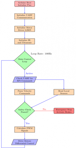
Figure 3. Arduino motor control system architecture
Inter-thread communication uses shared memory buffers with mutex protection to ensure data consistency. As shown in Figure 3, the Arduino runs a real-time control loop at 100 Hz, implementing PID control for precise motor actuation.
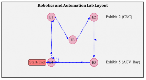
The size of the robotic library is 10 meters by 8 meters in which all the obstacles are available and they are used for the experiment in this research. Two types of obstacles are used one is the static obstacle and the other is the dynamic. The static obstacles are tables, equipment, and racks available. Figure 4 presents experimental laboratory layout showing navigation path. The dynamic obstacle moving people are temporarily placed objects. Several environmental factors are considered which include normal lighting 500 lux, low lighting 100 lux and different obstacle densities.
The system has undergone 100 navigation tests and 200 obstacle avoidance tests for systematic testing. Various performance characteristics are considered for the testing. These include accuracy, efficiency, obstacle awareness, success rate, computing resource usage, and user experience rating for 50 participants.
Figure 4. Experimental laboratory layout showing navigation path and obstacle locations
5.1 Navigation performance analysis
Table 1 gives a comparison of AI based SLAM system and traditional line following system. This AI based SLAM system is better in all parameters except computational load. It reduces the time by 40% in two times and it shows that this system is more efficient than traditional system. The developed system reduces the deviation by 65.6% i.e. from 3.2 cm to 1.1 cm. It shows that SLAM provides excellent localization accuracy. This SLAM tracking provides localization success rate of 98.2%. In this system, primary failures occur at 15% turns and 72% in low texture areas. Illumination changes are causing 13% failure results. Regression analysis is used to find the correlation between path deviation and SLAM tracking stability. A strong negative correlation R² = 0.83 was found between SLAM feature number and path segmentation. If ORB feature tracking is reduced to less than 300 features per frame, the path deviation increases by an average of 2.7 cm. This shows that sufficient feature density is important for navigation accuracy.
Table 1. Navigation performance comparison (100 trials)
|
Metric |
LF System |
AI SLAM System |
Improvement |
P-Value |
|
Average Tour Time (min) |
8.5 ± 0.4 |
5.1 ± 0.2 |
40.0% |
< 0.001 |
|
Path Deviation (cm) |
3.2 ± 0.8 |
1.1 ± 0.3 |
65.6% |
< 0.001 |
|
Average Speed (m/s) |
0.5 ± 0.1 |
0.8 ± 0.05 |
60.0% |
< 0.001 |
|
Localization Success Rate (%) |
100 (Fixed) |
98.2 ± 1.2 |
-1.8% |
0.023 |
|
Computational Load (CPU%) |
15 ± 3 |
78 ± 8 |
+420% |
< 0.001 |
5.2 Obstacle avoidance performance
Table 2 shows obstacle awareness performance is demonstrated after 200 trials. The system maintains a high success rate in challenging situations. The computational load is increasing due to the crowded environment, thus reducing the system performance. This is due to the more frequent path lab planning requirements. A success rate of 91.8% has been achieved in this situation. The ultrasonic sensor is providing emergency stop functionality. It provides 100% liability for immediate collision prevention. Parameter sensitivity analysis is performed to understand the relationship between YOLO confidence threshold and avoidance performance.
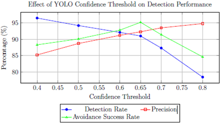
Figure 5 shows three confidence shots reduced from 0.7 to 0.5. It shows an 18% increase in detection rate but at the same time a 7% decrease in avoidance success rate. This is due to increased false positives. The analysis gives an optimal threshold of 0.65. I will discuss the balance accuracy of 92.3% and recall of 89.7%. The abstract avoidance success rate strongly suggests that R2 is equal to 0.76 with the time available for replanning. When comparing obstacles encountered within a 1.5 m range of the robot to obstacles encountered beyond 2.5 m, the avoidance success rate is 15% lower.
The optimal threshold of 0.65 balances detection rate, precision, and avoidance success
Figure 5. Parameter sensitivity analysis showing trade-offs in YOLO confidence threshold selection
Table 2. Obstacle avoidance performance (200 trials)
|
Scenario |
Success Rate (%) |
Detour Time (s) |
Path Increase (%) |
|
Single static obstacle |
100 |
2.1 ± 0.5 |
8.2 ± 2.1 |
|
Multiple static obstacles |
98.5 |
4.3 ± 1.2 |
15.7 ± 3.8 |
|
Dynamic obstacle (Moving) |
95.2 |
3.8 ± 1.1 |
12.3 ± 2.9 |
|
Crowded environment |
91.8 |
6.2 ± 1.8 |
22.5 ± 5.1 |
|
Emergency stop |
100 |
0.5 ± 0.1 |
0 |
|
Overall average |
97.1 |
3.4 ± 1.3 |
11.7 ± 3.5 |
5.3 Computational performance and system reliability
Figure 6 presents a comparison of computational resource utilization between AI SLAM and LF systems. Four parameter values namely CPU usage, memory usage, inference time and power consumption are reported. AISLAM inference time includes both SLAM and YOLO processing time. The CPU load utilization shows 78% utilization during navigation. It starts from 92% during simultaneous SLAM mapping and obstacle detection. Some important consequences of this high utilization are given below.
1. Thermal Management: The Raspberry Pi 4 reached 85°C after 25 minutes of operation without active cooling. Due to this, it reduces the CPU frequency from 1.8 GHz to 1.4 GHz. This frequency reduction increases the SLAM processing time. It increases the processing time by 35% and, therefore, causes frame drops in 2.1%.
2. Real-time Performance Impact: Simultaneous loop closure and solid obstacle detection in SLAM occur during peak load periods. The total processing latency for 15Hz operation is sometimes more than 66ms per frame. SLAM tracking loss recovers to 0.8% of frames in 100ms processing. YOLO frame dropping is 1.3% in dense obstacle conditions. This causes a 120ms delay between path planning re-planning events.
3. Reliability Concerns: Memory fragmentation increases SLAM initialization time by 45% in long-term testing over 10 hours. Periodic memory cleanup routines are required to maintain system stability.
4. Frame Drop Analysis: When SLAM and YOLO are under heavy load conditions, it shows 67% frame drop in the analysis. ORB-SLAM 2 has given 33 events during loop closure optimization. It sometimes monopolizes CPU resources for 150 to 200ms.
AISLAM inference time includes both SLAM and YOLO processing
Figure 6. Computational resource utilization comparison between systems
5.4 Environmental adaptability
The system works as shown in Table 3 of different environmental conditions available. The degradation of performers in low light conditions highlights the limitations of visual perception. This maintains good performance in high-traffic conditions with a success rate of 91.8%. This shows how effectively the system handles complex environments. It detects 70% localization failures in areas with low texture. This happens when reduces the ORB feature count to less than 200 features per frame. In low light conditions, there is noise in the camera which reduces the feature mapping accuracy by 40%. Five pixel tracking loss in ORB SLAM2 is due to faster motion blur. The key relationships have been identified as follows:
Table 3. Performance under varying environmental conditions with failure mode analysis
|
Environmental Condition |
Success Rate (%) |
Localization Accuracy (cm) |
Obstacle Detection Rate (%) |
Primary Failure Mode |
|
Normal lighting |
98.2 |
1.1 ± 0.3 |
96.5 ± 2.1 |
None |
|
Low lighting |
85.3 |
3.8 ± 1.2 |
78.2 ± 5.3 |
Feature extraction (72%) |
|
High crowding |
91.8 |
2.3 ± 0.8 |
92.7 ± 3.1 |
Computational overload (65%) |
|
Dynamic changes |
87.5 |
4.1 ± 1.5 |
85.4 ± 4.2 |
Tracking loss (58%) |
|
Mixed conditions |
82.6 |
5.2 ± 1.8 |
81.9 ± 4.7 |
Multiple factors |
5.5 User experience evaluation
Table 4 considers 50 of the participants for the user evaluation results. It is found that users consistently rated the AI-SLAM system for smooth navigation and obstacle avoidance. The time ratings obtained show that the increased computational complexity does not negatively affect the participants. The correlation between usability satisfaction and navigation smoothness is R = 0.78.
This suggests that reducing the startle moment during obstacle avoidance. Users are sometimes tolerant of poses due to sudden changes in direction. This indicates that the high response time ratings sometimes result in computational delays.
Table 4. User experience evaluation (N = 50)
|
Metric (1-5 Scale) |
LF System |
AI SLAM System |
Significance |
|
Overall satisfaction |
3.8 ± 0.6 |
4.5 ± 0.4 |
p < 0.001 |
|
Navigation smoothness |
3.2 ± 0.7 |
4.3 ± 0.5 |
p < 0.001 |
|
Obstacle avoidance |
3.5 ± 0.8 |
4.6 ± 0.3 |
p < 0.001 |
|
Information delivery |
4.1 ± 0.5 |
4.4 ± 0.4 |
p = 0.012 |
|
Response time |
4.2 ± 0.4 |
4.1 ± 0.5 |
p = 0.345 |
|
Ease of interaction |
4.3 ± 0.3 |
4.7 ± 0.2 |
p = 0.008 |
5.6 Technical contributions
This research demonstrates several important technical benefits. This research successfully implements the integration of embedded hardware with real-time visual SLAM, deep learning and path planning. A novel sensor fusion framework is integrated with YOLO detection in dynamic devices along with ORB features. The implementation of this model provides adaptive navigation without predefined paths. It is providing a fundamental change from the traditional approach to system modification. This capability of the system provides deployment of the system in various environmental conditions without expensive infrastructure. This research has achieved a balance between computational requirements and practical performance. The cost-effective hardware demonstrates that it can be easily implemented in the real world.
5.7 Limitations and challenges
This research found some limitations. The first important limitation is that excessive lighting provides low performance. The CPU utilization is 78% indicating that the computational intensity can limit the deployment. This indicates that the system requires a more resource-constrained platform. Scale in the monocular SLAM presents challenge for metric navigation. The limited ability to predict obstacle motion patterns offers another area for improvement. This research found that purely reactive obstacle avoidance is insufficient in highly dynamic environments. Recent approaches like DynaSLAM [13] and DS-SLAM [14] have shown promise in handling dynamic scenes through semantic segmentation and inpainting techniques. However, these methods are computationally intensive and may not be suitable for embedded systems like Raspberry Pi 4 without significant optimization.
5.8 Comparison with alternative approaches
Similar approaches are available for many cameras, including cost-effective solutions suitable for academic and laboratory applications. The performance between computational cost and the navigation capabilities of the system provides a strategic balance for real-world applications. In most situations, absolute performance is less important than reliability and affordability.
If we compare this system to more complex systems like DyGS-SLAM [15] which offers double-constrained optimization for better map reconstruction in dynamic scenes, or deep reinforcement learning approaches [16] that provide more adaptive navigation policies, this approach shows that autonomous navigation capabilities are achieved with simple hardware for advanced robotics technologies. The trade-off is between computational complexity and practical deployment feasibility.
This paper presents an AI-based visual navigation system. Designed for autonomous tour guide robots for academic laboratory environments. This research integrates ORBSLAM2 for real-time localization, YOLOv5 for obstacle detection, and A* algorithm for forward path planning. This research develops an assistant capable of navigating in a dynamic environment without predefined paths. Experimental results show improvements of 40% in two-time deduction, 65.6% in path deviation, and 95% in dynamic obstacle avoidance success rate. This is a system that strikes a practical balance between technical capabilities and implementation feasibility. This investigation shows that advanced autonomous navigation is achieved on cost-effective hardware. It has been proven by user evaluation that this system has improved experiments compared to the traditional method. Future work can focus on key areas. It will be possible to provide infrared and depth sensors as fusion sensors in this multimodal. It will be provided more robustness under different lighting conditions. The computational load will be reduced with quantization and pruning techniques. Predictive navigation that includes obstacle motion estimation will provide more intelligent path planning. Collaborative navigation with multi-robot coordination is possible. Also, it is possible to implement lifelong learning in the system with continuous environmental adaptation.
Future research directions could include incorporating semantic SLAM approaches like those in DS-SLAM for better handling of dynamic objects, or exploring lightweight implementations of dynamic scene handling techniques similar to DynaSLAM optimized for embedded systems. Additionally, hybrid approaches combining traditional path planning with reinforcement learning elements could provide more adaptive navigation policies for complex dynamic environments.
|
Symbol |
Description |
|
B |
Bounding box confidence score – (dimensionless) |
|
C |
Number of object classes – (dimensionless) |
|
f(n) |
Total estimated cost in A* algorithm – (dimensionless) |
|
g(n) |
Actual cost from start node to current node n – (dimensionless) |
|
h(n) |
Heuristic estimate from node n to goal – (dimensionless) |
|
L |
Wheel spacing (m) |
|
P(Object) |
Probability of object presence – (dimensionless) |
|
r |
Wheel radius (m) |
|
S |
Grid size in YOLO– (dimensionless) |
|
v |
Linear velocity (m·s⁻¹) |
|
x, y |
Robot position coordinates (m) |
|
m |
Map landmarks vector |
|
q |
Robot state vector [x,y,θ]T[x, y, θ]^T[x,y,θ]T |
|
x |
Robot trajectory vector |
|
z |
Camera observations vector |
|
Greek symbols |
|
|
θ |
Robot orientation angle (radians) |
|
ω |
Angular velocity (rad·s⁻¹) |
|
ωₗ, ωᵣ |
Left and right wheel angular velocities (rad·s⁻¹) |
|
Subscripts / Superscripts |
|
|
Notation |
Description |
|
g |
Goal position |
|
l |
Left wheel |
|
r |
Right wheel |
|
t |
Time step |
|
* |
Optimal value |
|
Abbreviations |
|
|
Abbreviation |
Full Form |
|
AI |
Artificial Intelligence |
|
CNN |
Convolutional Neural Network |
|
CPU |
Central Processing Unit |
|
IOU |
Intersection over Union |
|
LF |
Line Following |
|
MAP |
Maximum A Posteriori |
|
MTBF |
Mean Time Between Failures |
|
PWM |
Pulse Width Modulation |
|
ROI |
Return on Investment |
|
SLAM |
Simultaneous Localization and Mapping |
|
YOLO |
You Only Look Once |
[1] Cadena, C., Carlone, L., Carrillo, H., Latif, Y., Scaramuzza, D., Neira, J., Reid, I., Leonard, J.J. (2016). Past, present, and future of simultaneous localization and mapping: Toward the robust-perception age. IEEE Transactions on Robotics, 32(6): 1309-1332. https://doi.org/10.1109/TRO.2016.2624754
[2] Thrun, S., Beetz, M., Bennewitz, M., Burgard, W., Cremers, A.B., Dellaert, F., Fox, D., Hähnel, D., Rosenberg, C., Roy, N., Schulte, J., Schulz, D. (2000). Probabilistic algorithms and the interactive museum tour-guide robot Minerva. The International Journal of Robotics Research, 19(11): 972-999. https://doi.org/10.1177/02783640022067922
[3] Thrun, S., Bennewitz, M., Burgard, W., Cremers, A.B., Dellaert, F., Fox, D., Hähnel, D., Rosenberg, C., Roy, N., Schulte, J., Schulz, D. (1999). Minerva: A second-generation museum tour-guide robot. In Proceedings of the IEEE International Conference on Robotics and Automation (ICRA), Detroit, MI, USA, pp. 1999-2005. https://doi.org/10.1109/ROBOT.1999.770401
[4] Dissanayake, M., Newman, P., Clark, S., Durrant-Whyte, H.F., Csorba, M. (2001). A solution to the simultaneous localization and map building (SLAM) problem. IEEE Transactions on Robotics and Automation, 17(3): 229-241. https://doi.org/10.1109/70.938381
[5] Alvarado Vasquez, B.P.E., Gonzalez, R., Matia, F., De la Puente, P. (2018). Sensor fusion for tour-guide robot localization. IEEE Access, 6: 78947-78964. https://doi.org/10.1109/ACCESS.2018.2885648
[6] Redmon, J., Divvala, S., Girshick, R., Farhadi, A. (2016). You Only Look Once: Unified, real-time object detection. In Proceedings of the IEEE Conference on Computer Vision and Pattern Recognition (CVPR), Las Vegas, NV, USA, pp. 779-788. https://doi.org/10.1109/CVPR.2016.91
[7] Hart, P.E., Nilsson, N.J., Raphael, B. (1968). A formal basis for the heuristic determination of minimum cost paths. IEEE Transactions on Systems Science and Cybernetics, 4(2): 100-107. https://doi.org/10.1109/TSSC.1968.300136
[8] LeCun, Y., Bengio, Y., Hinton, G. (2015). Deep learning. Nature, 521(7553): 436-444. https://doi.org/10.1038/nature14539
[9] Bailey, T., Durrant-Whyte, H. (2006). Simultaneous localization and mapping (SLAM): Part II—State of the art. IEEE Robotics & Automation Magazine, 13(3): 108-117. https://doi.org/10.1109/MRA.2006.1678144
[10] Girshick, R., Donahue, J., Darrell, T., Malik, J. (2014). Rich feature hierarchies for accurate object detection and semantic segmentation. In Proceedings of the IEEE Conference on Computer Vision and Pattern Recognition (CVPR), USA, pp. 580-587. https://doi.org/10.1109/CVPR.2014.81
[11] Kazerouni, I.A., Fitzgerald, L., Dooly, G., Toal, D. (2022). A survey of state-of-the-art on visual SLAM. Expert Systems with Applications, 205: 117734. https://doi.org/10.1016/j.eswa.2022.117734
[12] Khatib, O. (1986). Real-time obstacle avoidance for manipulators and mobile robots. The International Journal of Robotics Research, 5(1): 90-98. https://doi.org/10.1177/027836498600500106
[13] Bescos, B., Fácil, J.M., Civera, J., Neira, J. (2018). DynaSLAM: Tracking, mapping, and inpainting in dynamic scenes. IEEE Robotics and Automation Letters, 3(4): 4076-4083. https://doi.org/10.1109/LRA.2018.2860039
[14] Yu, C., Liu, Z., Liu, X. J., Xie, F., Yang, Y., Wei, Q., Fei, Q. (2018). DS-SLAM: A semantic visual SLAM towards dynamic environments. In 2018 IEEE/RSJ International Conference on Intelligent Robots and Systems (IROS), Madrid, Spain, pp. 1168-1174. https://doi.org/10.1109/IROS.2018.8593691
[15] Zhu, F., Zhao, Y., Chen, Z., Jiang, C., Hui, Z., Hu, X. (2025). DYGS-SLAM: Realistic map reconstruction in dynamic scenes based on double-constrained visual SLAM. Remote Sensing, 17(4): 625. https://doi.org/10.3390/rs17040625
[16] Zhu, Y., Wan Hasan, W.Z., Harun Ramli, H.R., Norsahperi, N.M.H., Mohd Kassim, M.S., Yao, Y. (2025). Deep reinforcement learning of mobile robot navigation in dynamic environment: A review. Sensors, 25(11): 3394. https://doi.org/10.3390/s25113394
[17] Mur-Artal, R., Tardós, J.D. (2017). ORB-SLAM2: An open-source SLAM system for monocular, stereo, and RGB-D cameras. IEEE Transactions on Robotics, 33(5): 1255-1262. https://doi.org/10.1109/TRO.2017.2705103
[18] Xiao, L., Wang, J., Qiu, X., Rong, Z., Zou, X. (2019). Dynamic-SLAM: Semantic monocular visual localization and mapping based on deep learning in dynamic environment. Robotics and Autonomous Systems, 117: 1-16. https://doi.org/10.1016/j.robot.2019.03.012
[19] Fox, D., Burgard, W., Thrun, S. (1997). The dynamic window approach to collision avoidance. IEEE Robotics & Automation Magazine, 4(1): 23-33. https://doi.org/10.1109/100.580977