Mohanad H. Mahmood![]() | Omar Farooq Ali
| Omar Farooq Ali![]() | Mohannad Jabbar Mnati*
| Mohannad Jabbar Mnati*![]() | Bayan Mahdi Sabbar
| Bayan Mahdi Sabbar![]() | Alex Van Den Bossche
| Alex Van Den Bossche![]()
© 2025 The authors. This article is published by IIETA and is licensed under the CC BY 4.0 license (http://creativecommons.org/licenses/by/4.0/).
OPEN ACCESS
Brushless DC (BLDC) motors are widely used in industrial and automotive applications due to their high efficiency, reliability, and precise speed control. However, achieving optimal performance requires precise tuning of the Proportional-Integral-Derivative (PID) controller parameters. Traditional tuning methods often fail to provide the best control performance under varying operating conditions. In this paper, a Genetic Algorithm (GA)-based approach is proposed to optimize PID parameters for BLDC motor drive systems. The GA intelligently searches for the optimal parameter set by minimizing control errors and improving system stability. A mathematical model of the BLDC motor and PID controller is developed, followed by simulation and real-time implementation. The performance of the GA-tuned PID controller is compared with conventional PID tuning methods, demonstrating significant improvements in speed regulation, torque response, and robustness against disturbances. The proposed technology improves the overall efficiency of BLDC motor control, rendering it a viable option for industrial applications.
BLDC motors, PID, Genetic Algorithm, three phase inverter, intelligent control systems, motor drive performance
The growing demand for efficient electric vehicles (EVs) has led to a focus on Brushless DC (BLDC) motors due to their high efficiency, low maintenance, and compact design. However, controlling BLDC motors presents practical challenges, such as nonlinear dynamics, torque ripple generation, and performance degradation. Traditional control methods, such as Proportional-Integral-Derivative (PID) controllers, have inherent limitations, including sensitivity to parameter variations and difficulties in tuning for optimal performance across various operating conditions. These approaches are not sufficiently adaptable to dynamic changes and therefore cannot be used for real-time purposes. Applying conventional control techniques is challenging and time-consuming, making it relatively expensive and time-consuming.
New control techniques are demanded to improve the performance of the BLDC drive. The study is driven by the goal of using contemporary optimization methods, particularly population-based metaheuristic algorithms, to form adaptable speed control systems, which are expected to provide better torque control and to increase efficiency. This in-depth knowledge on problems and limitations constraining BLDCM controllability establishes a sound base for further investigation, leading to effective solutions development, overall increasing research motivation.
Brushless DC (BLDC) motors have become increasingly popular in modern industrial applications due to their high efficiency, reliability, and superior performance compared to traditional brushed motors. BLDC motors offer several advantages over brushed DC and induction motors, including improved speed-torque characteristics, high dynamic response, greater efficiency, longer operational life, quieter operation, broader speed ranges, and reduced electromagnetic interference (EMI). Additionally, their high torque-to-size ratio makes them ideal for applications where space and weight are critical, such as in robotics, electric vehicles, aerospace, and automation systems [1-5].
The BLDC (Brushless DC) motor belongs to the family of synchronous motors with torque, current, voltage, and rpm relationship linear, which makes its modeling similar to that of a DC motor. While brushed motors use mechanical commutation, BLDC motors rely on electronic commutation. In this concept, the motor has fixed electromagnets (stator) and rotating permanent magnets (rotor), which eliminate the necessity for brushes and a mechanical commutator. This design overcomes the challenge of transferring current to a moving armature, as the armature is fixed. Instead, an electronic controller manages power distribution, replicating the function of a brushed DC motor's commutator. However, achieving precise speed control of BLDC motors remains a critical challenge, as their performance is highly dependent on the effectiveness of the control strategy employed.
PID controller is one of the most popular control skills in motor speed control because of their simplicity and robustness. The PID controller's performance largely depends on the appropriate design of its gain constants (Kp, Ki, and Kd). Many attempts have been made to tune the parameters of the PID controller [6-9]. The Ziegler-Nichols method is one such method that is commonly followed, however, in some real systems it may not be appropriate for the reason that it causes the system to be marginally stable while tuning, hence inducing instability. Another option for performing correct PID parameter tuning is lambda tuning method, although this method is not very fast. Moreover, interval polynomial criterion for stability and Lyapunov’s theorem have been employed in PID controller parameters design which is complex and analytic.
In the past few years, computational intelligence (CI) techniques have been increasingly used for PID tuning on account of their capability to address complex nonlinear systems. Fuzzy logic control (FLC), artificial neural networks (ANN), and particle swarm optimization (PSO), to give a few examples, have been effectively used to optimize PID gains. Fuzzy logic based PID controllers adjust PID parameters based on the system response for better performance under different operating conditions. PSO can also be applied to the PID parameter optimization, a method for incrementally looking for optimal solution in a predetermined search space [10-14].
In this paper, a Genetic Algorithm is proposed to optimally design a PID controller for speed control of a Brushless dc motor. This method is developed in order to enhance and optimize the PID parameters for accurate speed regulation under load variations and external disturbances. A comparative study is conducted to establish the superiority of the GA tuned PID Networks controller over the existing PID controller by presenting some simulation and experimental results. The results of this study will promote the development of intelligent control methods of BLDC motors towards higher performance and reliability of motorized systems.
The application of Genetic Algorithms (GAs) for the intelligent tuning of PID parameters in BLDC motors has been extensively investigated to enhance performance and efficiency. Researchers have employed GAs to address nonlinear dynamics and optimize control parameters efficiently, hence enhancing stability, accuracy in speed, and torque control across various situations. Table 1 encapsulates essential studies and approaches pertinent to this strategy, emphasizing their strategies and results in enhancing BLDC motor function.
Table 1. Literature review on tuning techniques for PID control in BLDC motors
|
Author(s) & Year |
Methodology |
Optimization Approach |
Key Findings |
|
Zhao and Xi, 2020, [15] |
Adaptive Genetic Algorithm (AGA) for PID |
Dynamic adjustment of crossover and mutation probabilities based on fitness |
AGA improves convergence speed, reduces overshoot, and enhances steady-state accuracy |
|
Suseno, and Ma’Arif, 2021, [16] |
Simulation and Hardware Testing |
Genetic Algorithm (GA) |
GA tuning reduces overshoot (<10%), improves rise/settling time, and outperforms trial-and-error methods |
|
Kristiyono and Wiyono, 2021, [17] |
Two-level control system combining PID and fuzzy logic |
Fuzzy logic-based real-time autotuning |
Improved rise time (0.0025s), settling time (0.057s), and overshoot (5.42%) |
|
Zeng et al., 2023, [18] |
ADRC system design for five-phase motors using Tracking Differentiator (TD) and Extended State Observer (ESO), validated through simulation and experiments |
Genetic Algorithm (GA) for multi-objective optimization; iterative tuning with fitness functions; three-step optimization of current and speed loops |
GAADRC outperformed ADRC and PI controllers in overshoot, adjustment time, and disturbance rejection; reduced tuning time and improved robustness for real-world applications |
|
Naqvi et al., 2024, [19] |
Multi-objective optimization of PI controllers for BLDC motor speed control and energy efficiency in EVs using simulation models |
PSO (Particle Swarm Optimization) and DE (Differential Evolution) algorithms for constrained optimization |
DE outperformed PSO in minimizing MSE (0.1809) and energy consumption (0.984 kWh). Speed control efficiency improved by ~95.4%, energy efficiency by ~3.1% |
|
Kroičs and Būmanis, 2024, [20] |
MATLAB/Simulink simulation and experimental testing |
Adaptive Fuzzy-PID controller combined with sinusoidal PWM |
Improved speed response, reduced overshoot, minimized torque ripple, and harmonic content |
|
Krishnamoorthy et al., 2024, [21] |
EWOA-Tuned PID Controller for BLDC Motors |
Enhanced Whale Optimization Algorithm |
Achieved faster rise time (0.1600s), shorter settling time (0.1900s), and minimal overshoot (0.0001%), improving speed control and stability significantly |
|
Moloody et al., 2024, [22] |
PID tuning for vibration control in flexible manipulators using MATLAB simulations |
Modified Differential Evolution Optimization Algorithm (MDEOA) combining dynamic mutation and crossover strategies |
Achieved 25–30% improvement in vibration suppression and system stability compared to traditional methods |
|
Zhang et al., 2024, [23] |
Air suspension control using fuzzy PID and dynamic modeling of a 1/4 vehicle model in MATLAB/Simulink |
Genetic Algorithm (GA) optimization |
GA-optimized fuzzy PID control markedly enhanced ride comfort by diminishing vehicle vertical acceleration by 30%, suspension travel by 26%, and tire dynamic load by 9% in comparison to passive and fuzzy PID controls |
|
Moali et al., 2024, [24] |
Backstepping, PID-Type-1 FLC, PID-Type-2 FLC |
Genetic Algorithm (GA) |
PID-Type-2 FLC with GA offers superior robustness and precision in windy conditions |
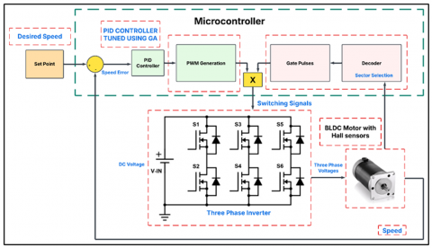
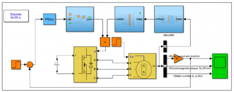
The suggested controller architecture for a 3-phase Brushless DC motor, depicted in Figure 1, incorporates numerous essential components to guarantee efficient and accurate performance. The system initiates with a reference source that supplies the required speed or torque input for the motor. This inputs functions as the reference value for the control system. A PID controller processes the error signal, defined as the discrepancy between the reference input and the actual motor performance, and modifies control parameters like voltage or current to reduce the error and ensure stable operation. The driver circuit acts as an interface between the controller and the motor, amplifying the control signals to drive the power electronics in the inverter. Hall effect sensors are employed to detect the rotor position and provide feedback to the controller, enabling precise switching of the inverter phases based on the rotor’s position.
The converter circuit modifies the DC input power to an appropriate voltage level for the motor, while the inverter circuit transforms this DC power into three-phase AC power by six-step switching. The transition between steps is coordinated with the rotor position, as identified by the Hall effect sensors. Table 2 illustrates the correlation between the rotor position and the respective inverter switching step. The 3-phase Brushless DC motor functions according to control signals from the inverter, generating mechanical motion in reaction to the electrical input. This integrated system guarantees seamless and effective functioning of the motor.
Figure 1. Block diagram of the proposed controller for three-phase Brushless DC motor
Table 2. Switching intervals, hall effect signals, and phase switch states for 3-phase BLDC motor
|
Switching Interval |
0° 60° |
60° 120° |
120° 180° |
180° 240° |
240° 300° |
300° 360° |
|
|
Sequence |
1 |
2 |
3 |
4 |
5 |
6 |
|
|
Hall Effect Signals |
HA |
1 |
1 |
0 |
0 |
0 |
1 |
|
HB |
0 |
1 |
1 |
1 |
0 |
0 |
|
|
HC |
0 |
0 |
0 |
1 |
1 |
1 |
|
|
Switches |
Ph. A |
S1,S1′ |
S1,S1′ |
OFF |
S1,S1′ |
S1,S1′ |
OFF |
|
Ph. B |
S2,S2′ |
OFF |
S2,S2′ |
S2,S2′ |
OFF |
S2,S2′ |
|
|
Ph. C |
OFF |
S3,S3′ |
S3,S3′ |
OFF |
S3,S3′ |
S3,S3′ |
|
The Genetic Algorithm (GA) optimization has significantly improved motor control performance for Brushless DC (BLDC) motors. The GA-PID controller consistently achieves lower overshoot compared to the Z-N method, demonstrating its ability to fine-tune PID parameters, resulting in a more stable response to changes in setpoint or load conditions. This reduction in overshoot is crucial for applications requiring quick stabilization after disturbances or setpoint changes. The GA's iterative nature allows it to refine PID parameters effectively, resulting in a control strategy that reacts promptly while avoiding overshoot. This balance between responsiveness and stability significantly enhances the overall control performance of the BLDC motor.
The GA-PID controller exhibits a lower steady-state error compared to traditional methods, indicating that the motor can maintain its desired speed or position more accurately over time. The optimization process of the GA allows for the integral component of the PID controller to be finely tuned, eliminating persistent errors that can arise due to load variations or external disturbances. This improvement in steady-state performance not only enhances the accuracy of the motor control but also contributes to the overall efficiency of the system.
The results in Tables 1 and 2 highlight the robustness of the GA-PID controller under varying operating conditions, suggesting that its optimization capabilities enable it to adapt to changes in system dynamics more effectively than traditional tuning methods. This adaptability is crucial in real-world applications where conditions can fluctuate and performance maintenance is paramount.
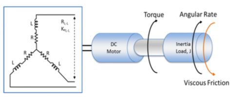
3.1 Mathematical modeling of BLDC motor
Although the principal difference between conventional DC and BLDC motors is their more complex composition, which directly affects performance and control. In contrast, the inductive and resistive components of the BLDC motor are time-varying variables due to the phase change and therefore need an elaborate analysis. As shown in Figure 2, the motor is connected in a symmetrical 3-phase "wye" configuration, and its mathematical model is based on a classic DC motor model modified for the peculiarities of BLDC motors.
Figure 2. Mathematical model and symmetrical 3-Phase star connection of BLDC motor
The basic voltage equation using the armature voltage of the BLDC motor is proposed and shown as Eq. (1), providing the foundation for studying the electrical behavior and performance properties of the motor.
$\begin{aligned} & V_a=R \cdot I_a+\frac{d}{d t}\left(L_a \cdot I_a+M_{a b} \cdot I_b+M_{a c} \cdot I_c\right)+e_a \\ & V_b=R \cdot I_b+\frac{d}{d t}\left(L_b \cdot I_b+M_{b a} \cdot I_a+M_{b c} \cdot I_c\right)+e_b \\ & V_c=R \cdot I_c+\frac{d}{d t}\left(L_c \cdot I_c+M_{c a} \cdot I_a+M_{c b} \cdot I_b\right)+e_c\end{aligned}$ (1)
As the three-phase currents of the BLDC motor satisfy Eq. (2), this dependence is essential to provide symmetrical operation and realistic modeling of the electrical dynamics of the motor.
$I_a+I_b+I_c=0$ (2)
Eq. (1) can now be simplified to obtain a more concise representation, thus rendering the phase voltage equation of BLDC motors in matrix notation, as presented in Eq. (3). This expression leads to a simple and tractable form, which can be easily handled for both analysis and computation of motor dynamics.
$\begin{gathered}{\left[\begin{array}{l}V_a \\ V_b \\ V_c\end{array}\right]=\left[\begin{array}{lll}R & 0 & 0 \\ 0 & R & 0 \\ 0 & 0 & R\end{array}\right]\left[\begin{array}{l}I_a \\ I_b \\ I_c\end{array}\right]+} {\left[\begin{array}{ccc}L-M & 0 & 0 \\ 0 & L-M & 0 \\ 0 & 0 & L-M\end{array}\right] \frac{d}{d t}\left[\begin{array}{l}I_a \\ I_b \\ I_c\end{array}\right]+\left[\begin{array}{l}e_a \\ e_b \\ e_c\end{array}\right]}\end{gathered}$ (3)
To formulate a full mathematical model of the electromechanical system, it is imperative to integrate the motor's equations of motion, as delineated in Eq. (4). These equations delineate the correlation between electrical inputs and mechanical outputs, facilitating a comprehensive examination of system dynamics.
$T_e-T_L=j \frac{d \omega_m}{d t}+B \cdot \omega_m$ (4)
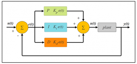
3.2 PID controller
The "error" signal, as shown in the PID (Proportional-Integral-Derivative) controller Figure 3, is a parameter that indicates the error between the desired set point and the measured value of the process variable. The process controller takes the minimum error and adjusts the commanded process control inputs dynamically to reduce the minimum error to near zero to improve system performance. The PID method involves tuning three separate constant coefficients: proportional, integral, and derivative (Kp, Ki, and Kd, respectively). These parameters are usually further identified by taking an empirical approach or using a trial-and-error method. The PID controller can be described as where the integral, derivative, and proportional gain, respectively, and the formulation is given by Eq. (5).
$u(t)=K_p e(t)+K_i \int e(t) d t+K_D \frac{d}{d t} e(t)$ (5)
Figure 3. Block diagram of the PID controller 3-phase Brushless DC motor
4.1 Genetic Algorithm-based PID tuning
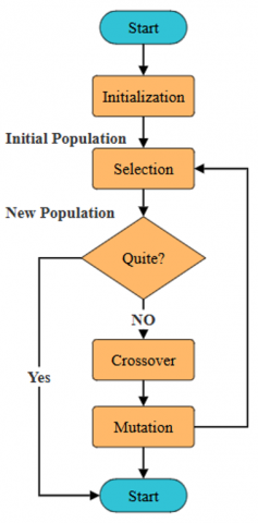
GAs is an optimization algorithm based on the evolutionary principles of natural selection, and therefore, they are good for solving nonlinear equation systems and complex modeling problems. Contrary to deterministic techniques, GA utilizes probabilistic transition rules, which enable it to efficiently search the solution space. It works on a population of candidate solutions, called individuals or chromosomes, which develop iteratively over several generations.
Each generation of each population is simulated generation-wise, guiding the solutions to evolve with a fitness function and genetic operators (reproduce, crossover, and mutate). These operators are similar to operators realized in biological processes and make the algorithm improve the obtained candidate solutions. The Genetic Algorithm traditionally starts off with a randomly produced initial population, as shown in Figure 4. This population is encoded into a set of real or binary strings as chromosomes.
Figure 4. The flowchart of the PID controller 3-phase Brushless DC motor
The performance of each individual is assessed by an objective function that assigns a fitness value to measure the extent to which the solution satisfies the specified requirements. The fitness function directs the selection process, guaranteeing that people with superior performance are more likely to influence the subsequent generation. The GAs uses a repeated process to get closer to the best solutions, making it a useful tool for solving tough, complex optimization problems.
The integral of Time-weighted Absolute Error (ITAE) plays an important role for PID controllers. It evaluates the performance of the control both in terms of the accuracy of the error and for how long the error persists. This metric is especially relevant for dynamic systems, because it penalizes settled error from the setpoint. This is especially critical in systems such as temperature, speed, and position controls, which a long error can drive the system into instability or sufficiently reduce the performance.
The influence of ITAE in control can change greatly with operating conditions (as in Eq (6)). In applications with rapid-load or setpoint changes, a PID controller with an ITAE-optimized tuning may respond more stably and rapidly. This strategy permits better disturbance rejection since the controller responds more quickly in order to keep the plant's output under control. Alternatively, slower or less variable systems tend to result in over-aggressive control by pursuing minimum ITAE, which can lead to oscillations or loss of control.
ITAE $=\int_0^{\infty} t \cdot|e(t)| d t$ (6)
where, e(t) is the error signal at t.
The selection of PID tuning parameters, e.g., proportional gain, integral time, and derivative time, can also have an effect on the performance of the controller according to the ITAE criterion. For instance, if the proportional gain is increased, then the steady-state error can be reduced, at the expense of an increased overshoot and oscillation, which can result in a lower ITAE score.
4.2 Genetic Algorithm steps
A GA application for optimal design of a control system, specifically BLDC motor control, needs a proper choice of parameters: not only of the control algorithm, but also of the GA operator: population size, number of generations, crossover rate, and mutation rate. The size of the population and the number of solutions in one generation, it can enlarge the population to generate diversity and facilitate exploration of the solution space. However, when the number of individuals is large, more computational time is required, and it takes excessive time for an overall evaluation, and balancing between diversity and computation time are required.
The number of generations corresponds to the number of times the generations of the algorithm are moved to evolve the population. The more generations there are, the more chances we have to optimize and refine solutions, which can result in better optimization. But too large value of this parameter may cause the yielding of lesser and lack of exploitation of the solution space, which affects the quality of the final solution.
The crossover rate regulates the number of crossover operations that take place between pairs of parents to create offspring. The greater the possible rate of crossover, the more the genetic pieces might mix, but it is too large genetic exchange in too-well-adapted individuals or deletion of valuable genetic material may occur. The right crossover rate for balancing between exploration and exploitation is important.
Finally, the mutation rate affects the probability of random detrimental mutations on members of the population. The mutation rate is typically 1% to 5% as a way to preserve diversity and avoid premature convergence.
The Genetic Algorithm employs iterative processes of initialization, fitness assessment, selection, crossover, and mutation to advance a population of solutions towards optimal outcomes.
Step 1: Initialize the parameters with a population of stochastic solutions, including crossover rate, mutation rate, number of clusters, and number of generations. Ascertain the coding mode.
Step 2: Calculate and assess the value of the fitness function.
Step 3: Execute the crossover and mutation operations to form the new cluster.
Step 4: Continue Step 2 until the optimal value is achieved.
4.2.1 Coding and decoding
Genetic Algorithms do not operate on the parameters but rather work on a population of strings (also called chromosomes). To overcome this problem, the vector of controller parameters has to be transformed into a well-structured string referred to as a chromosome to guarantee a proper optimization procedure.
4.2.2 Fitness serves
Fitness is a quantitative measure to estimate how good a chromosome is at solving a given problem. According to the “survival of the fittest” philosophy, chromosomes having a higher fitness value will get more opportunities to donate more offspring to subsequent generations to accelerate evolution. performance measure is inherently related to fitness function when the function determines how good the solution performs in the context of Genetic Algorithms. These values are determined by minimizing an objective function, the minimizing process being repeated iteratively until the optimization algorithm converges to a solution.
4.2.3 Reproduction
Reproduction is a fundamental operator in Genetic Algorithms, rooted in the principle of "survival of the fittest." During each generation, chromosomes from the current population are selected and replicated into the next generation based on their reproduction probability ($P_{r i}$), as defined in Eq. (7). This process ensures that fitter chromosomes, with higher fitness values, have a greater likelihood of being propagated, thereby preserving and amplifying advantageous traits in subsequent generations.
$P_{r i}=\frac{F_i(\theta)}{\sum_{i=1}^{P_l} F_i(\theta)}$ (7)
where, $P_l$ is the population size.
4.2.4 Crossover
Reproduction steers the Genetic Algorithm's search process toward the most promising individuals, ensuring that the fittest solutions are prioritized for propagation. The crossover operation complements this by facilitating the exchange of genetic information between pairs of chromosomes selected from the mating pool. Through a probabilistic approach, crossover introduces diversity and enables the mixing of genetic material at designated splice points, fostering the creation of new, potentially superior offspring while preserving advantageous traits from parent chromosomes.
4.2.5 Mutation
In Genetic Algorithms, the gene pool often becomes increasingly homogeneous as superior genes dominate over successive generations, potentially causing premature convergence to a suboptimal solution. To address this limitation, the mutation operator is introduced with an appropriate probability to maintain genetic diversity within the population. Mutation involves introducing occasional random changes to selected genes, with mutation points chosen randomly across the population. This mechanism ensures the exploration of new areas in the solution space, reduces the risk of stagnation, and prevents the algorithm from being trapped in a non-optimal solution, thereby enhancing its ability to find global optima.
Genetic Algorithm-Based PID Tuning: The process can be summarized as follows: GA begins by generating an initial random population, typically with a small population size, to enable faster optimization and convergence of the controller. The PID parameters (Kc), (Ti), and (Td) encoded into chromosomes, forming the initial population. The fitness of each chromosome corresponds to the performance of the PID parameters it represents. Each set of PID parameters is passed to the PID controller, and the system's complete response for each parameter set is evaluated using a cost function. The Integral of Time-weighted Absolute Error (ITAE) is chosen as the cost function due to its superior performance in minimizing error over time (as in a Eq. 6).
The optimization process iteratively cycles through genetic operations selection, crossover, mutation until the specified number of generations is completed, ultimately achieving the best fitness value. The primary objective of the GA is to identify global PID values ((Kc), (Ti), and (Td)) that minimize the fitness value, ensuring optimal system performance.
5.1 Simulation results
This section presents the simulation of a BLDC motor controlled by a PID controller, as illustrated in Figure 1. The simulation studies encompass various scenarios, including a sudden step increase in speed, a sudden decrease in speed, and gradual variations in speed (both increase and decrease). The MATLAB/Simulink simulation model for BLDC motor speed control is depicted in Figure 5. Tables 3 and 4 outline the BLDC motor specifications and driving characteristics utilized in this study. The simulation evaluates the performance of the PID controller, which has been optimally tuned using the Genetic Algorithm, ensuring precise speed regulation and robust control under diverse operating conditions.
Figure 5. MATLAB/Simulink model for BLDC motor speed control using PID controller
Table 3. Main specifications of the BLDC motor used in the simulation
|
Parameters |
Specifications |
|
Rated power (w) |
125 |
|
Rated voltage (V) |
24 |
|
Rated speed (r.p.m) |
3000 |
|
Rated torque (N.m) |
0.44 |
Table 4. Genetic Algorithm parameters for PID controller tuning
|
Parameters |
Specifications |
|
Rated power |
120W |
|
Input voltage |
12-30VDC |
|
Output current |
5A-8A |
|
Hall electrical degree |
60°/300° 120°/240° |
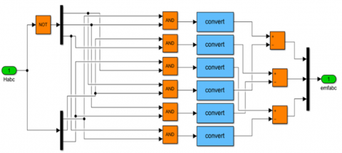
Usually, a 3-phase BLDC motor uses six power switches in its full-bridge power converter to generate 3-phase voltage synchronously. The turn-on and turn-off of these transistors is controlled by the rotor position, which is key for the high performance of the motor. Typically, the motor starter is supervised with three Hall sensor units. These Hall sensors are essential in that the rotor position is sensed by the decoder block for the estimation of the reference current signal vector aligned with BEMF. The goal is to guarantee accurate control and synchronization of the movement of the motor.
Figure 6 shows the MATLAB simulation block diagram exhibiting back EMF creation inside the decoder. This arrangement accurately and reliably combines the Hall sensor data with the control system.
Figure 6. MATLAB simulation block diagram for generating back EMF using decoder
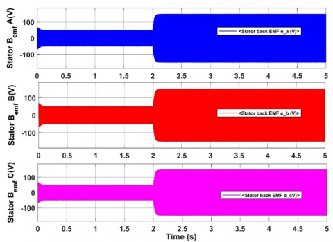
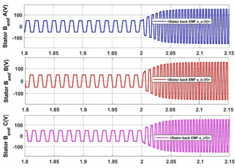
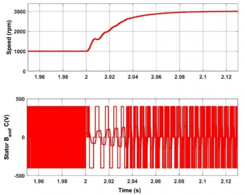
Back electromotive force (BEMF) of the BLDC motor for different achievable speeds from 1000 RPM to 3000 RPM is shown in Figure 7. This change also illustrates the complex characteristics of BEMF through motor speed variation, which can also be regarded as the stability and efficiency of the motor controller. Figure 7(b): A zoomed view of the BEMF profile around the critical interval of time (1.8 s < t < 2.15 s) is given in Figure 7(b). In this case study, we have concentrated on the smooth and steady shape of the BEMF waveform as a motor speed up and slows down, thereby keeping distortion to a minimum and tracking of rotor position more accurate. The simulation results in MATLAB/Simulink validate that the control strategy ensures stable and predictable BEMF characteristics at varying speeds, which is necessary for precise motor driving and best performance.
(a) from 0 to 5S
(b) from1.8ms to 2.15ms
Figure 7. Back EMF profile of BLDC motor at variable speeds (1000 RPM to 3000 RPM)
Figure 8 shows the response of motor speed utilizing the GA-PID tuning method as opposed to the conventional PID tuning method based on the Ziegler-Nichols (Z-N) approach. The performance of both controllers is assessed using a comparison spanning 0 RPM, 1000 RPM, 2000 RPM, and 3000 RPM. The simulation results in MATLAB/Simulink reveal that the performance of the GA-PID controller is better than that of the PID in terms of settling time as well as overshoot and stability with all speed levels. Which means with less error, GA-PID controller always achieves accurate and steady precision speed tracking and the traditional Z-N tuned PID controller shows apparent oscillations and slower convergence at higher speeds.
Figure 8. Comparison of speed response using GA-PID and traditional Z-N PID controllers at various speeds (0 RPM, 1000 RPM, 2000 RPM, 3000 RPM)
The evolutionary algorithm-derived optimal parameters assist the GA-PID controller facilitate a more precise response to dynamic changes in speed, ensuring strict control and robust operation. The difference is most noticeable in speed level transitions where the GA-PID controller maintains a smooth response without losing performance. On the whole, the findings have revealed that the GA-PID tuning method significantly outperforms the classical Z-N approach, and accordingly, it is the more promising approach for BLDC motor speed control.
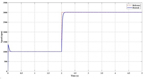
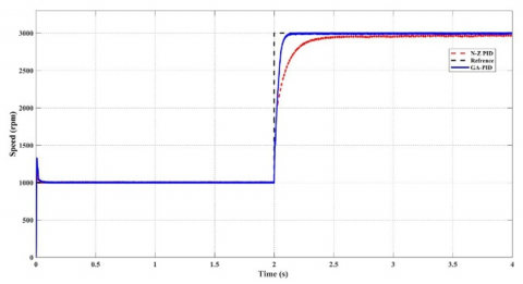
The comparison between the GA-PID controller and the conventional Ziegler-Nichols (Z-N) tuned PID controller with nominal speed is also illustrated in Figure 9. The simulation results show that the GA-PID controller can obtain accurate speed tracking and has better dynamic performance than the Z-N PID controller. As for step changes in reference speed, the response of the GA-PID controller happens sooner with no overshoot and a smaller steady-state error, and the motor speed follows the reference value more closely.
Figure 9. Comparison of speed tracking between GA-PID and Z-N PID controllers with reference speed
By comparison, the Z-N PID controller tends to take more time for settling, and the speed is more deviated away from its reference, especially during a speed that’s varying or step speed. The GA-PID controller’s feature of being able to adapt and optimize PID parameters under different operating conditions can cope with the changing objects, so that it has the advantages of good completion quality and stability, etc. The findings support that the GA-PID controller is a robust and stable solution for controlling BLDC motors as compared to the Z-N based tuning method in all transient and steady states.
The advantages of Genetic Algorithms in PID tuning can be demonstrated by the comparison, so that GA-PID controller is the optimum one in applications required relatively high precision and strong dynamic self-tuning performance.
The present research also examines GA-PID controller performance in relation to the Z-N method. Key performance measures, like overshoot, settling time, and steady-state error, are essential in evaluating how effectively these control strategies are able to control various system dynamics.
The overshoot for the GA-PID controller is much lower than that for the Z-N method, because the Genetic Algorithm could perform optimization. This makes PID AP parameters more nuanced in order to reduce overshooting and achieve smoother responses. The Z-N based method, being fast, can lead to over-aggressive parameter values, which lead to increased overshoot especially in systems having higher order of dynamics.
Sitting time is smaller for the GA-PID controller than the Z-N method because it covers more the solution's field and it also optimizes the PID parameter with desired dynamics of the system. The integral part of the GA-PID controller has been modified to eliminate steady-state error in a particular time, such that this control is suitable for any application that demands quick and accurate control.
Figure 10 shows the signals of the Hall sensor and the phase-to-phase BEMF of the BLDC motor, highlight its importance for the operation of the motor. The Hall-sensor signals delivered as digital pulses serve for precision monitoring of the position of the rotor, and thus for precise synchronization to commutate.
Figure 10. Hall sensor signals and phase-to-phase back EMF of BLDC motor
The phase-to-phase BEMF waveform itself is a sine wave, which is indicative of the motor's electromagnetic response while it is spinning and can take on any number of forms based on rotor speed and position. The relationship between the Hall sensor signals and the BEMF is employed to give a smooth operation characteristic in the motor with low torque ripple and high efficiency. This synchronization is essential for stable speed control and the best performance, particularly on a dynamic velocity or load change.
The BLDC motor's variable speed range (1000–3000 RPM) and matching back electromotive force (BEMF) waveform are depicted in Figure 11. The outcomes demonstrate steady motor functioning at different speeds and smooth BEMF generation.
Figure 11. Variable speed (1000 to 3000 RPM) and corresponding back EMF of BLDC motor
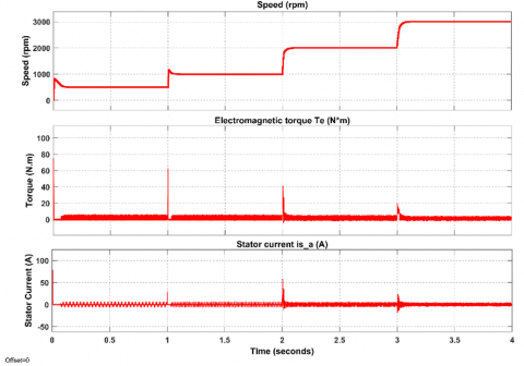
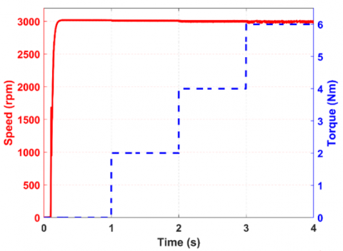
Figures 12 and 13 demonstrate the efficacy of the GA-PID controller. Speed to Torque Figure 12 shows the torque response and immediate response with smooth operations, low overshoot, and smooth transitions. Figure 13 shows the GA-PID speed responses for different speeds. (1000 to 3000 RPM), verifying accurate speed following and dynamic adaptability.
Figure 12. Speed, torque response, and current response of BLDC motor using GA-PID controller
Figure 13. Speed response of BLDC motor using GA-PID controller at variable speeds (1000 to 3000 RPM)
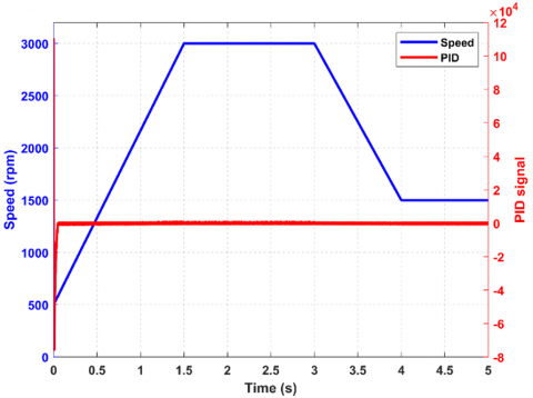
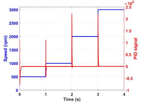
Figure 14 shows the response of the continuously varying proportional-type speed controller system at an initial frequency of 500 RPM, which is increased to a maximum of 3000 RPM and then brought down to 1500 RPM. The graph shows the PID signal response for the complete process, clearly demonstrating the system's precision and stability during acceleration and deceleration. The PID control law has the capability to adapt the control signal such that smooth transitions are made and overshoots are minimized, demonstrating its stability for handling the system dynamics of speed changes. 13 This value is an important yardstick in evaluating the performance of the control system at different operating conditions.
Figure 14. PID control signal response for gradual speed variation (500 to 3000 RPM, then 3000 to 1500 RPM)
The dynamic behavior of the control system GA-PID, at which the wind is blowing at variable speeds, is also described in Figure 15. As you can see, the graph shows the PID control, which warms up to follow the setpoint change and slows down to catch the setpoint and overspeed in a controlled manner, and will oscillate to stop. The Genetic Algorithm (GA) is combined with the PID controller to improve the parameter tuning of the PID, resulting in better performance under disturbance. This value showed the stability of the GA-PID method for accurate speed control even in a real-time implementation. Performance of GA-PID for VS is given in Figure 16. This figure helps explain how the Proportional-Integral-Derivative (PID) parameters are tuned by using the Genetic Algorithm (GA) according to the system dynamic behavior at different operating conditions.
Figure 15. Dynamic response of GA-PID controlled variable speed system
Figure 16. Variable speed of GA-PID controlled
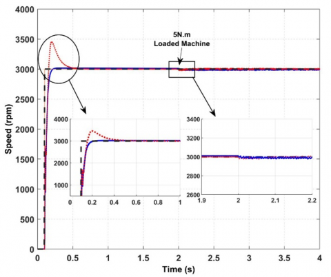
A BLDC(GA-PID) system, as an example of load torque variation, is depicted in Figure 17. It could be observed from the data how well the GA-PID controller accommodates load changes, reducing overshoot and settling time, yet maintains steady and rapid speed control.
Figure 17. GA-PID speed response under variable load torque conditions
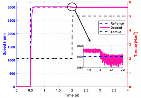
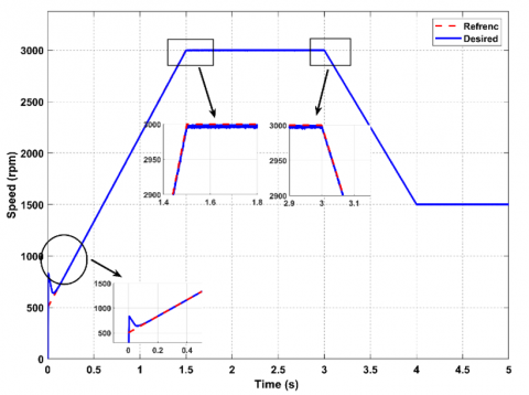
Figure 18 shows the GA-PID controller's speed response as it progressively raises and lowers speed relative to the target speed. By successfully reducing overshoot and undershoot during transitions, the graph shows how well the GA-PID algorithm maintains a steady and smooth response. This feature demonstrates how well the controller can adapt to dynamic changes in load conditions, guaranteeing that the real speed barely deviates from the intended trajectory.
Figure 18. Speed response comparison of GA-PID controller with desired speed trajectory
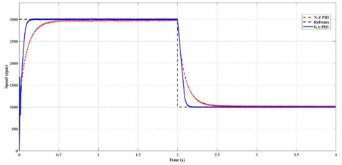
The speed response of the N-Z (Ziegler-Nichols) PID controller and the GA (Genetic Algorithm) PID controller is compared in Figure 19 for two different speed ranges: 1000 to 3000 RPM and then 3000 to 1000 RPM. The findings show that, especially when adjusting from high to low speeds, the GA PID controller performs better due to less overshoot and quicker settling periods. When compared to the conventional N-Z method, this illustrates how well the GA PID tuning method improves system stability and dynamic response.
(a) 1000-3000 RPM
(b) 3000-1000 RPM
Figure 19. Comparison of N-Z PID and GA PID controller performance at varying speeds
In this study Parallel Genetic Algorithm (GA) has been compared with other intelligent techniques, including Particle Swarm Optimization (PSO) and Fuzzy Logic Control (FLC) in controlling the performance of a Brushless DC motor.
The Genetic Algorithm (GA) is a distributed search algorithm that is good at searching diverse solution spaces, which is very suitable for the problem of complex and nonlinear systems. However, such method may be computationally expensive and need much experimentation for tuning parameters properly. Particle Swarm Optimization (PSO) is one of the popular intelligent optimization algorithms that model the social behavior of birds or fish which provide simplicity and convenience in codes writing. It needs less tuning parameters, so it converges faster and adapts immediately to the variations in the search space. But it is susceptible to premature convergence in high-dimensional spaces and the selection of inertia weight and acceleration factors.
Fuzzy Logic control (FLC) It is a control method that simulates human reasoning. It is useful in systems with imprecise or uncertain data, it deals with nonlinearities, and it can deliver robust control when no accurate model exists. But they must be designed by an expert in rules and membership functions, and can be slow, needing a lot of tuning.
GA is well suited to solving complex optimization problems, PSO is suitable for real-time systems with SMPS goals and low computational burden, and Fuzzy Logic Controller works very well in systems with unpredictable worlds and has adaptation features.
5.2 Hardware implementation and real-time testing
The experimental testing bench for the GA-PID controller is described in detail in the section "Hardware Implementation" in the study. The quality of the sensors employed in the experiences is a key parameter influencing the measurement and, overall, the performance of the control system. The motor speed, position, and torque were measured by high-accuracy sensors, and thus, reliable data were obtained within an assigned tolerance. Speed sensor Accuracy of ± 0.5% of full-scale is critical for the accurate control of motor performance.
The data acquisition was set to 1 kHz to allow to capture of fast dynamics of the system and to allow the controller to react quickly to changing operating points. But the performance of the data acquisition system was limited by the processing ability of the utilized hardware, and would bring in the latency if the total computational load was higher than the hardware power.
There was several hardware constraints encountered in the experiment that can have an influence on the results. The control hardware of the system was of bounded processing capabilities, and as such could introduce delays to the implementation of control commands, ultimately affecting the controller's overall performance. The stability of the power source also affected the experiments, as change in voltage level could cause motor performance and sensor readings to change. These constraints highlight the necessity to take the hardware into account for the results' interpretation and to optimize the control strategies.
Figure 20 presents the hardware implementation and real-time testing setup using a Brushless DC (BLDC) motor controlled by an Arduino Mega 2560. The Arduino Mega 2560 is a powerful microcontroller board equipped with 54 digital input/output pins and 16 analog inputs, making it suitable for complex projects that require multiple sensors and actuators. In this configuration, the Arduino interfaces with the BLDC motor to demonstrate effective real-time control, validating the proposed control algorithms and showcasing their practical application in managing motor performance under varying conditions.
Figure 20. Hardware setup for BLDC motor operation with arduino mega 2560
Figure 21 shows the Hall sensor signals recorded from a Brushless DC (BLDC) motor running at three different speeds: 1000, 3000 and 5000 RPM. Hall sensor signals help communicate the motor, so you can have good control of the motor.
(a) 1000 RPM
(b) 3000 RPM
(c) 5000 RPM
Figure 21. Hall sensor signals recorded from a Brushless DC (BLDC) motor
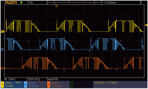
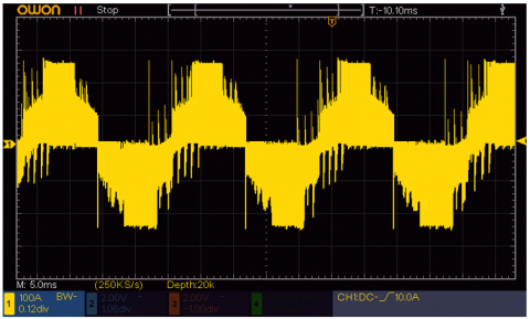
Figure 22 shows the phase EMF signal generated by the brushless DC (BLDC) motor at three different speeds: 1000, 3000, and 5000 RPM, respectively. The phase EMF signals are important for analyzing motor performance and efficiency. With this type of signal, we can observe the voltage induced in each phase due to rotation. The amplitude and frequency of the signals increase with the speed; the higher the speed, the more back EMF is generated by the motor. At 1000 RPM, the signals are of relatively small magnitudes and frequency, while at 5000 RPM, the signals have large amplitudes and fast oscillations. Such information is crucial to study the motor dynamics and to optimize the control arrangement.
(a)
(b)
(c)
Figure 22. Phase EMF signals recorded from a Brushless DC (BLDC) motor: a)1000 RPM, b)3000 RPM, and c)5000 RPM
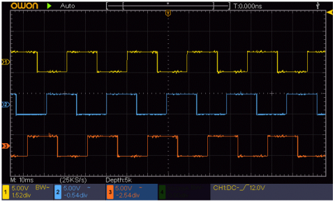
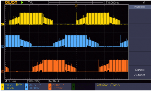
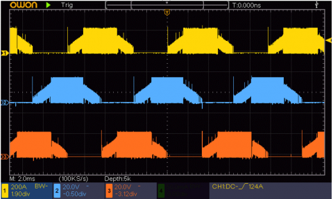
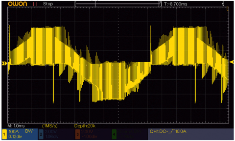
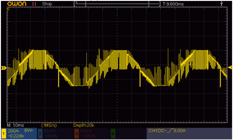
The phase-to-phase EMF signals of a BLDC motor at 1000, 3000, and 5000 RPM are displayed in Figure 23. Each waveform represents the voltage difference across a pair of motor phases, providing an example of motor operation at different loads. Amplitude of phase-to-phase EMF signals increases with increasing speed, indicating positive voltage generation and improved performance of the motor. The distinctive features that appear in the signals at multiple RPMs are rich in information about motor performance and are essential tuning parameters for control algorithms in applications such as robotics and electric vehicles.
(a) 1000 RPM
(b) 3000 RPM
(c) 5000RPM
Figure 23. Brushless DC (BLDC) motor phase-to-phase EMF signals were recorded
The Fitness Function: F is one of the important purposes for maximizing the performance of the Brushless DC (BLDC) motor based on the Genetic Algorithm (GA) (As in Eq (9)). The PIDCO methodology measures PID controller performance through key performance indicators, including overshoot, settling time, and steady-state error. The objective of the GA is to reduce the steady state value of the F, in this way driving it toward the values of PID of the set of PID parameters, leading to the best dynamic behavior of the control system for the BLDC motor.
$F=\omega_1 \cdot Overshoot +\omega_2 \cdot Setting \cdot Time +\omega_3 \cdot Steady - State \cdot Error$ (9)
where, $\omega_1$, $\omega_2$ and $\omega_3$ are weights assigned to each performance metric.
The optimization functions of the GA are associated with improving the performance characteristics of the BLDC motor. The GA is intended to minimize the fitness function in order to minimize overshoot, settling time, and grand steady state error in order to keep the motor accurate in performance with time. GA can iteratively search different PID parameters to meet the requirement of load variations and external disturbances. As the GA runs through generations to determine the fitness to the function, it discovers sets of parameters that guarantee low iterations of F, and in this way it tunes the controller strategy for the known dynamics of the BLDC motor.
The fitness function may be further extended to incorporate other performance characteristics, such as energy efficiency or response time under other levels of loading, can be as a result provides a more integrated optimization methodology that takes into account the overall efficiency of the BLDC motor. This all GAs approach further makes the GA practical to use in realistic settings where more than one performance objective shall be optimally balanced in the motor operation situation.
The paper shows that the use of GA for closed-loop tuning of PID parameters gives much better results in terms of the Brushless Direct Current (BLDC) motor performance. This GA method, in the sense that the search engine is automatically programmed, can reduce the tuning time of the motor parameters while enhancing the control’s accuracy and stability by tuning the motors. The simulation results show that the new control strategy can significantly improve the dynamic characteristics of the rotor system. Hence, a new WPD-PR controller based on the input shaping and the PID control theory is formed.
For Future work should concentrate on improving the Genetic Algorithm for more efficient and flexible control of these generators in different operating conditions. Furthermore, extension studies that integrate hybrid methods of GA, for example, with fuzzy logic or machine learning, can yield more effective solutions for dynamic environments. Furthermore, the investigation into the adoption of this intelligent tuning function to various sorts of motors and control systems would be another powerful tool to extend the applicability and to evolve the automation industry and the robot field. Moreover, experimental validation in different operating conditions will also be necessary to validate the generality of the results and to mitigate possible drawbacks discussed in this paper.
The study highlights the potential of integrating Genetic Algorithm methods with advanced technologies like machine learning and deep learning to improve control performance in complex systems, including Brushless DC motors. Machine learning can improve fitness evaluation by identifying patterns and correlations, while deep learning can predict system behavior, providing valuable insights for optimization. Hybrid optimization techniques, combining GA with other algorithms like Particle Swarm Optimization (PSO) or Differential Evolution (DE), can create more robust frameworks for complex solution spaces. Edge computing and the Internet of Things (IoT) can enhance the application of GA in real-time control systems, allowing for more responsive and adaptive control strategies in rapidly changing system dynamics.
[1] Maghfiroh, H., Ramelan, A., Adriyanto, F. (2021). Fuzzy-PID in BLDC motor speed control using MATLAB/Simulink. Journal of Robotics and Control (JRC), 3(1): 8-13. https://doi.org/10.18196/jrc.v3i1.10964
[2] Dilmi, I., Bouguerra, A., Djrioui, A., Chrifi-Alaoui, L. (2021). Interval type-2 fuzzy logic-second order sliding mode based fault detection and active fault-tolerant control of brushless DC motor. Journal Européen des Systèmes Automatisés, 54(3): 475-485. https://doi.org/10.18280/jesa.540311
[3] Hamad, A.R., Al-Jarwany, Q.A., Sabbar, B.M., Mnati, M.J., Ali, A.H., Van Den Bossche, A. (2023). Speed control of BLDC motor: Design and simulation based on neural network. In 2023 2nd International Engineering Conference on Electrical, Energy, and Artificial Intelligence (EICEEAI), Zarqa, Jordan, pp. 1-5. https://doi.org/10.1109/EICEEAI60672.2023.10590555
[4] Adebayo, I., Aborisade, D., Adetayo, O. (2020). Optimization of proportional integral derivative parameters of brushless direct current motor using genetic algorithm. Journal of Engineering Research and Reports 16(3): 24-32. https://doi.org/10.9734/jerr/2020/v16i317170
[5] Youssef A.M. (2018). Operations of electric vehicle traction system. Mathematical Modelling of Engineering Problems, 5(2): 51-57. https://doi.org/10.18280/mmep.050201
[6] Ajel, A.R., Abbas, H.M.A., Mnati, M.J. (2021). Position and speed optimization of servo motor control through FPGA. International Journal of Electrical & Computer Engineering (2088-8708), 11(1): 319-327. https://doi.org/10.11591/ijece.v11i1.pp319-327
[7] Dahbi, M., Doubabi, S., Rachid, A. (2020). Real time implementation for a low-cost control for BLDC motor current ripple minimization. European Journal of Electrical Engineering, 22(1): 63-69. https://doi.org/10.18280/ejee.220108
[8] Manda, P., Veeramalla, S.K. (2021). Brushless DC motor modeling and simulation in the MATLAB/SIMULINK software environment. Adv Modelling Analysis B, 64(14): 27-33. https://doi.org/10.18280/ama_b.641-404
[9] Bujgoi, G., Sendrescu, D. (2024). Tuning of PID Controllers using Reinforcement Learning for Nonlinear Systems Control.
[10] Yıldırım, Ş., Bingol, M.S., Savas, S. (2024). Tuning PID controller parameters of the DC motor with PSO algorithm. International Review of Applied Sciences and Engineering, 15(3): 281-286. https://doi.org/10.1556/1848.2023.00698
[11] Chen, K., Xiao, B., Wang, C., Liu, X., Liang, S., Zhang, X. (2023). Cuckoo coupled improved grey wolf algorithm for PID parameter tuning. Applied Sciences, 13(23): 12944. https://doi.org/10.3390/app132312944
[12] Ye, S., Sun, L. (2020). Design of PID intelligent controller combining immune genetic algorithm. Journal of Physics: Conference Series, 1574(1): 012010. https://doi.org/10.1088/1742-6596/1574/1/012010.
[13] Baciu, A., Lazar, C. (2023). Iterative feedback tuning of model-free intelligent PID controllers. Actuators, 12(2): 56. https://doi.org/10.3390/act12020056
[14] Abbas, H.M.A., Chisab, R.F., Mnati, M.J. (2021). Monitoring and controlling the speed and direction of a DC motor through FPGA and comparison of FPGA for speed and performance optimization. International Journal of Electrical & Computer Engineering, 11(5): 3903-3912. https://doi.org/10.11591/ijece.v11i5.pp3903-3912
[15] Zhao, J., Xi, M. (2020). Self-tuning of PID parameters based on adaptive genetic algorithm. IOP conference series: Materials science and engineering, 782(4): 042028. https://doi.org/10.1088/1757-899X/782/4/042028
[16] Suseno, E.W., Ma'arif, A. (2021). Tuning of PID controller parameters with genetic algorithm method on DC motor. International Journal of Robotics and Control Systems, 1(1): 41-53. https://doi.org/10.31763/ijrcs.v1i1.249
[17] Kristiyono, R., Wiyono, W. (2021). Autotuning fuzzy PID controller for speed control of BLDC motor. Journal of Robotics and Control (JRC), 2(5): 400-407. https://doi.org/10.18196/jrc.25114
[18] Zeng, R., Zhao, J., Xiong, Y., Luo, X. (2023). Active disturbance rejection control of five-phase motor based on parameter setting of genetic algorithm. Processes, 11(6): 1712. https://doi.org/10.3390/pr11061712
[19] Naqvi, S.S.A., Jamil, H., Iqbal, N., Khan, S., Lee, D.I., Park, Y.C., Kim, D.H. (2024). Multi-objective optimization of PI controller for BLDC motor speed control and energy saving in Electric Vehicles: A constrained swarm-based approach. Energy Reports, 12: 402-417. https://doi.org/10.1016/j.egyr.2024.06.019
[20] Kroičs, K., Būmanis, A. (2024). BLDC motor speed control with digital adaptive PID-fuzzy controller and reduced harmonic content. Energies, 17(6): 1311. https://doi.org/10.62441/nano-ntp.v20iS4.2
[21] Krishnamoorthy, S.K., Das, N., Gudimetla, P., Emami, K. (2024). Enhanced speed control for BLDC motors using WOA-integrated PID controller optimization. IEEE Access, 12: 162465-162475. https://doi.org/10.1109/ACCESS.2024.3480349
[22] Moloody, A., As’arry, A., Hong, T.S., Kamil, R., Zolfagharian, A. (2025). PID controller parameter tuning based on a modified differential evolutionary optimization algorithm for the intelligent active vibration control of a combined single link robotics flexible manipulator. Journal of Advanced Research in Applied Sciences and Engineering Technology, 52: 234-258. https://doi.org/10.37934/araset.52.1.234258
[23] Zhang, S., Li, M., Li, J., Xu, J., Wang, Z., Liu, S. (2024). Research on ride comfort control of air suspension based on genetic algorithm optimized fuzzy PID. Applied Sciences, 14(17): 7787. https://doi.org/10.3390/app14177787
[24] Moali, O., Mezghani, D., Mami, A., Oussar, A., Nemra, A. (2024). UAV trajectory tracking using proportional-integral-derivative-type-2 fuzzy logic controller with genetic algorithm parameter tuning. Sensors, 24(20): 6678. https://doi.org/10.3390/s24206678