Abdullah Jamil* | Masri B. Baharom | Abd Rashid B. Abd Aziz
© 2022 IIETA. This article is published by IIETA and is licensed under the CC BY 4.0 license (http://creativecommons.org/licenses/by/4.0/).
OPEN ACCESS
Researchers and engineers are continuously working to improve the overall efficiency of internal combustion engines by modifying the engine designs and configurations. As new engine designs are introduced, the in-cylinder flow behaviour becomes more and more complex. The maximum output and efficiency that can be achieved from a single cylinder engine depends upon the amount of air entrapped in the combustion chamber during intake stroke. A novel crank-rocker (C-R) engine was designed and fabricated in Universiti Teknologi PETRONAS (UTP), Malaysia and is currently under optimization phase. This paper narrates the in-cylinder cold-flow analysis of the C-R engine considering widely used industrial automotive software, Converge CFD. The turbulent behaviour of the C-R engine was compared with that of the conventional crank-slider engine. The initial and boundary conditions for the C-R engine simulations were set according to the benchmarked crank-slider engine. RNG k-ε turbulence model was used to generate the data plots for tumble & swirl ratios, cylinder pressure, TKE, turbulent dynamic viscosity and vorticity at cold-flow conditions. It was observed that the C-R engine has better air scavenging properties and can achieve better air-fuel mixing that can lead to emission-free combustion. This study will help in understanding the turbulent airflow behaviour within the curved cylinder under the influence of rocking piston motion, and its advantageous flow properties compared to those in crank-slider engines.
CAD model, CFD analysis, crank-rocker, flow analysis, visualization
Modern spark-ignition internal combustion engines are being optimized using different geometrical and conditional variations, for better air-fuel mixing and efficient combustion [1-4]. For example, Port or Indirect injection was used instead of carburettor and eventually, direct injection instead of port injection was introduced as the most efficient method so far. Downsizing, Supercharging and Turbocharging are other methods to increase engine efficiency and to reduce the exhaust emissions.
It has been observed and proved that the flame propagation is rapid during the combustion stroke if the air-fuel mixing is efficient during intake and compression strokes [5]. Therefore, the effective air-fuel mixing is considered and promoted during the optimization of IC engines. It is of major importance to study the behaviour of engine fluid flows and to improve engine quality, it is extremely important to understand the flow properties in the cylinder. This is because engine efficiency is significantly related to the in-cylinder flow conditions [5, 6]. The greater the flow motion, greater the turbulence, more relative flow eddies are generated which results in efficient air-fuel mixing, and vice versa.
The combustion chamber geometry is of importance when fluid-flow is discussed. This geometry includes the cylinder liner, the piston head crown, and head roof [7-9]. Turbulence flow fields have a great effect on the efficient combustion process. The total process of thorough mixing during the intake phase gives rise to turbulent flow conditions which is then intensified by the piston motion and the geometry of combustion chamber [10, 11]. Also, there are many fluid flow characteristics that depends upon the geometry of the engine cylinder [12]. For example, the swirl or tumble flows, length scale, vorticity etc. These geometry parameters include intake port design, bore/stroke ratio, and cylinder head shape.
High-intensity turbulence, including great energy eddies, tumble, and swirls, is one of the most significant factors for smoothening the ignition process. In spark-ignition engines, tumble motion is most occurred [13, 14]. Different intake port geometries generate varying turbulent flows which can be very significant for improving the air-fuel mixing properties. These intake properties include the intake manifold geometry, intake port design, intake valve configurations, valve lift, piston geometry, piston position and combustion chamber geometries [2].
A single rotor Wankel engine was developed and tested at wide open throttle [15]. Researchers considered it a promising alternative to reciprocating engines. They concluded that the performance in terms of power, torque and efficiency were improved by increasing the energy fraction of hydrogen in the fuel mixture, which also reduced the HC and NOX emissions. Hence, this engine can be used for hybrid applications.
New Concept Rocker Engine [16] was introduced which has two opposing pistons attached to rocker linkages that are coupled to a common crankshaft in the center. This was described as an improvement over crank-slider engines in terms of kinematics, compactness, and its ability to modify the piston stroke and compression ratio as per required. The authors claimed that this engine has 8 times lower piston-to-liner force than the conventional engine.
Another Opposed Piston Engine was designed, tested and patented with a slightly different configuration [17]. The researchers observed that the engine produced high thermal efficiency and reliability with lower fuel consumption and maintenance. As an improvement to the previous designs, a novel crank-rocker (C-R) engine, which is a type of toroidal engine, was invented in Universiti Teknologi PETRONAS (UTP), Malaysia with the intent to decrease the frictional losses present in the conventional crank-slider engine [18]. The engine geometric dimensions were benchmarked from the Modenas ACE115 crank-slider engine.
In the present paper, CFD analysis is carried out to investigate the airflow behaviour within the crank-rocker engine at cold-flow conditions and its comparison with the conventional crank-slider engine. Re-Normalization Group (RNG) k-ε turbulence model is used with operating conditions set at standard temperature and pressure i.e., 303 K and 101325 Pa. This study is useful in understanding the flow behaviour and velocity field properties within the C-R engine and how it differs from the conventional crank-slider engines.
1.1 Theoretical background
In order to understand the effect of air induction system and geometric variations on the combustion characteristics, visualization of in-cylinder flows can be practiced [19]. Numerical simulation is a reliable tool to demonstrate the effects of valve lifts and varying intake configurations. A recent increase in computational fluid dynamics (CFD) is observed due to its effectiveness for the advanced design in IC engines [20]. Complete air flow throughout the cycle can be visualized with the help of cold-flow simulations [6]. This includes the capturing of induced air, predicting the development of swirl, tumble, and squish flows, mixing of fuel droplets with induced air. In CFD, mass, momentum and energy are solved using balanced equations for discretised geometry. These set of equations are called Navier-Stokes equations which govern the fluid motion and are subjected to initial and boundary conditions [21].
$\begin{aligned} \frac{\partial \mathbf{v}}{\partial t}+(\mathbf{v} . \nabla \mathbf{v}) &=-\frac{1}{\rho} \nabla p v_{o} \nabla^{2} \mathbf{v} \\ \nabla \cdot \mathbf{v} &=0 \end{aligned}$ (1)
where, v(x,t) is the fluid velocity, p is the pressure, ρ is density and vo is the molecular kinematic viscosity. The air-fuel mixture upon entering the combustion chamber through the intake valve flows in all possible directions. Large-scale flow motions are energized by boundary conditions which eventually cascade to smaller scales and thus the boundary conditions are of importance. Renormalizing the above-mentioned Navier-Stokes equations derives the Re-Normalization Group (RNG) k-ε variation of Reynold’s Averaged Navier-Stokes (RANS) turbulence model, where k is the transported variable turbulent kinetic energy and ε is the transported variable rate of dissipation of turbulent kinetic energy.
$\frac{\partial}{\partial t}(\rho k)+\frac{\partial}{\partial x_{i}}\left(\rho k u_{i}\right)=\frac{\partial}{\partial x_{j}}\left[\left(\mu+\frac{\mu_{t}}{\sigma_{k}}\right) \frac{\partial k}{\partial x_{j}}\right]+P_{k}-\rho \varepsilon$ (2)
$\frac{\partial}{\partial t}(\rho \epsilon)+\frac{\partial}{\partial x_{i}}\left(\rho \epsilon u_{i}\right)=\frac{\partial}{\partial x_{j}}\left[\left(\mu+\frac{\mu_{t}}{\sigma_{\epsilon}}\right) \frac{\partial \epsilon}{\partial x_{j}}\right]+C_{1 \epsilon} \frac{\epsilon}{k} P_{k}-C_{2 \epsilon}^{*} \rho \frac{\epsilon^{2}}{k}$ (3)
where,
$C_{2 \epsilon}^{*}=C_{2 \epsilon}+\frac{C_{\mu} \eta^{3}\left[1-\frac{\left(2 S_{i j} S_{i j}\right)^{\frac{1}{2}} k}{\epsilon \eta_{o}}\right]}{1+\beta \eta^{3}}$ (4)
This version of RANS is suitable especially for moderately complex behaviours like separating and swirling flows for in-door small scales eddies. The turbulent viscosity and the numerical constants in the RNG equations can be derived from the standard k-ε model. Due to the restrictions of cylinder liner and piston wall, the flow performs rotational motion. The component of flow around the axis of cylinder is called swirl flow and the component having its axis perpendicular to the cylinder axis is called tumble flow. The swirl ratio and tumble ratio are defined mathematically as:
$R_{s}=\frac{\omega_{s}}{2 \pi N} ; R_{t}=\frac{\omega_{t}}{2 \pi N}$ (5)
where, Rs, Rt, ωs, ωt and N are the swirl ratio, tumble ratio, angular velocity of flow around swirl axis, angular velocity of flow around tumble axis and engine angular speed, respectively.
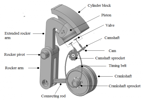
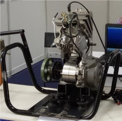
The crank-rocker (C-R) engine was successfully designed, fabricated, and tested and its schematic as well as the final assembly are shown in Figure 1. The curved piston does not slap against the cylinder surface as in the case of conventional crank-slider engine, this reduces the frictional losses in the engine [22].
(a)
(b)
Figure 1. (a) Design of Crank-Rocker Engine and (b) Fabricated and Assembled C-R Engine [18]
Another important factor that can make the crank-rocker engine more powerful than the conventional crank-slider engine is the possibility of using biofuel for combustion. This is because biofuels are future source and possible alternative of the engine fuels. One of the main advantages of having biofuel is the reduction of greenhouse emissions, as many researchers have asserted the importance of biofuels [23]. Biofuel in the form of LPG and natural gas can be used in crank-rocker engine.
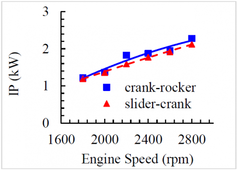
The analytical procedure was carried out to evaluate the Indicated Torque (IT) and Power (IP) comparison of crank-rocker and crank-slider engines whereas, the experimental dynamometer analysis was performed on the crank-rocker engine to evaluate the HC and NOx emissions. These results are shown in Figure 2. In the light of these experimental and analytical results, the advantages of crank-rocker engine over the conventional crank-slider engine are summarized and tabulated (Table 1).
(a)
(b)
Figure 2. (a) Indicated Torque (IT) and (b) Indicated Power (IP) verses engine speed comparison of crank-rocker engine and crank-slider engine [18]
Table 1. Comparison between crank-rocker engine and crank-slider engine [18, 22, 24]
|
Crank-Rocker Engine |
Crank-Slider Engine |
|
The crank-radius can be changed without altering the stroke length. |
The stroke is dependent on the crank size. |
|
Kinematics configuration allows the piston to dwell longer at TDC. |
The piston does not dwell at TDC. |
|
The curve piston is not in direct contact with the cylinder wall. The contact is only through the piston rings. |
Piston slaps against the cylinder wall which introduces frictional losses. |
|
The shaking force & moment can be balanced. |
Requires many cylinders for effective balancing. |
|
Very Compact. |
Less compact as many cylinders are required for best performance. |
|
Can be designed to have slower compression stroke for better mixing while faster combustion stroke for better power. |
The rate of compression stroke is almost similar of the combustion stroke. |
The improvement of engine performance parameters is a result of the curved cylinder and the turbulence intensity inside the combustion chamber because the geometry has significant effect on airflow which results in better mixing, better combustion, and reduced exhaust emissions. To validate this hypothesis, a comparison of various CFD simulations is presented on the crank-rocker and crank-slider engines during the intake stroke. The numerical cold-flow analysis is performed using the renowned commercial CFD software CONVERGE. Combustion and exhaust strokes analyses are beyond the scope of this research as mostly the intake flow structures describe the overall thorough combustion and engine efficiency.
This research is focused on the independent variable which affects the incoming air-fuel mixture during the intake stroke; this variable is the cylinder liner orientation. In case of crank-slide engine, the liner is straight-walled with normal pointing in one direction. Whereas, in case of crank-rocker engine, the liner is curved with normal pointing towards the direction of tangent to the liner at that point.
The piston performs translatory motion in crank-slider engine, while in crank-rocker engine, the piston moves freely within the liner walls. Hence, it performs an angular displacement around the axis which defines the curvature of cylinder liner. The crank-slider engine dimensions are benchmarked from Modenas ACE115 crank-slider engine, and its specifications are given in Table 2.
Table 2. Specifications of crank-slider engine and crank-rocker engine
|
Parameter |
Crank-Slider |
Crank-Rocker |
|
Liner curvature radius |
- |
138.21mm |
|
Throw angle |
- |
21° |
|
Engine Speed |
2000 rpm |
|
|
No. of strokes |
4 |
|
|
No. of valves |
2 |
|
|
Stroke |
50.6 mm |
|
|
Bore |
55 mm |
|
|
Engine displacement |
120 cc |
|
|
Compression ratio |
8.0 |
|
There are dependent variables which define the turbulent behaviour of the airflow within the engine cylinder. These variables specifically quantify certain characteristics of the fluid-flow like, the measure of turbulence intensity (TI), kinetic energy (TKE), the number of induced eddies, the size of largest eddies, variation in turbulence in multiple engine cycles etc.
2.1 Pre-processing
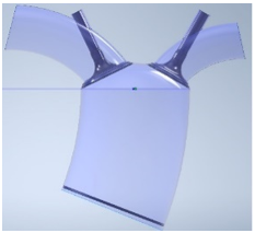
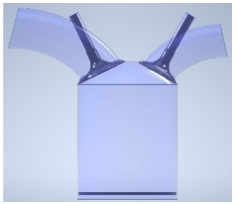
To acquire the characteristic properties like TI, TKE, tumble and swirl etc, using CFD, computer-aided design (CAD) of both engines is modeled using Autodesk Inventor Professional 2020 as per the geometric dimensions of actual engines. These include the combustion chamber with hemisphere roof, cylinder liner, intake/exhaust ports, intake/exhaust valves and piston wall. The CAD models of both 2-valve single cylinder engines are shown in Figure 3.
(a)
(b)
Figure 3. CAD Models of (a) Crank-Rocker engine and (b) Crank-Slider engine
(a)
(b)
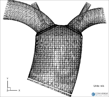
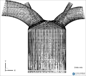
Figure 4. Adaptive Mesh Refinement (AMR) of (a) Crank-Rocker Engine and (b) Crank-Slider Engine at BDC
All simulations are performed using CONVERGE at standard temperature and pressure conditions i.e., 303 K and 101325 Pa, based on the benchmarked crank-rocker engine. A full hydrodynamic transient simulation with compressible gas flow solver is initialized for four engine cycles, where the first 3 cycles are ignored to wash out the initial condition effects [24-26]. Renormalization Group (RNG) k-ε turbulence model is used due to its effectiveness and accuracy for in-cylinder flow behaviour analysis. A base grid size of 4mm is generated with fixed embedding of scale 3 near intake and exhaust valve and 2 inside cylinder to accurately capture the flow. Adaptive Mesh Refinement (AMR) (shown in Figure 4) is used to enhance the mesh at each timestep to accurately solve at each cell nodes near the moving boundaries and flows. This allows low computational power required in terms of CPU processing which saves time. In other words, a lesser number of CPU cores is needed for certain calculations within a given amount of time.
2.2 Timing
The piston and valve motions are synchronized as per the actual engine specifications. 0° Crank-Angle (CA) is defined as the position where the piston is at 30° before top dead centre (bTDC) during the exhaust stroke. The 4-stroke engine cycle completes at 720° CA. Intake valve opens and closes at 52° bTDC and 37° aBDC respectively while the exhaust valve opens and closes at 35° bBDC and 58° aTDC respectively. This valve timing is benchmarked from the current conventional crank-slider engine (Modenas ACE115). The timing diagram is shown in Figure 5.
Figure 5. Valve timing diagram
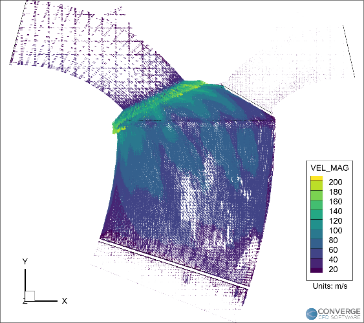
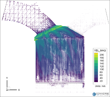
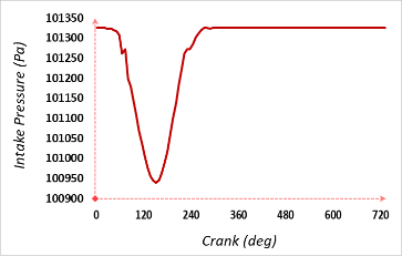
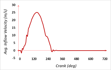
The flow velocity vectors are generated in the postprocessing of solver as shown in Figure 6. The static pressure at the intake port is at atmospheric pressure i.e., 101325 Pa. As the intake valve opens, from 30° CA to 210° CA, the pressure drops to around 100950 Pa, due to which the air-fuel mixture enters the cylinder. The port pressure immediately starts increasing as the intake valve closes. The average intake velocity at the intake port reaches a maximum of 25 ms-1 at around maximum intake valve position. The plots of intake port pressure and average velocity are shown in Figure 7.
(a)
(b)
Figure 6. In-cylinder flow vectors visualization of (a) Crank-Rocker engine and (b) Crank-Slider engine during Intake at 500° CA
(a)
(b)
Figure 7. (a) Intake port static pressure and (b) Average intake flow velocity for both engines at cold-flow conditions
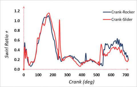
(a)
(b)
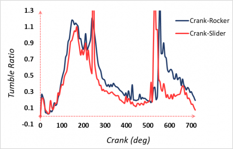
Figure 8. (a) Swirl ratio and (b) Tumble ratio trend within the cylinders of crank-rocker and crank-slider engines at cold-flow conditions
Swirl and tumble ratio profiles of the airflow within the cylinder region are analyzed. It can be clearly seen that during the intake from 30° CA, the swirl ratio increases reaching its maximum and slowly diminishes as piston reaches BDC. Again, the swirl flow increases during the exhaust phase as piston moves upwards, but this fluctuation is less than that during intake. Tumble flow, on the other hand, instantly jumps to maximum point at around 520° CA to 530° CA at the end of expansion at power stroke as seen in Figure 8.
During exhaust stroke, the tumble structure breaks down. When compared to crank-slider engine, the swirl trend of crank-rocker engine is almost the same except during the exhaust phase and just before the spark ignition at around 360° CA, the increase of 50% swirl in C-R engine is observed. This can be attributed to the geometrical profile of the curved cylinder along with the upward piston motion. This results in a higher swirl air movement and a more thorough air-fuel mixing as compared to the crank-slider engine just before spark ignition.
As for the tumble flow, the C-R engine has undoubtedly higher tumble ratio than the crank-slider engine throughout the engine cycle but at 360° CA, an increase of 33% in tumble is observed for crank-rocker engine. It can be attributed to the curved cylinder itself, as it facilitates the inherent shape of the tumble motion to be generated during the intake and compression strokes by the motion of piston. The swirl ratio and tumble ratio comparison for crank-rocker and crank-slider engines are presented in Figure 9.
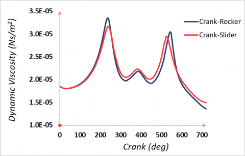
The internal cylinder pressure is set at the atmospheric conditions i.e., 101325 Pa. During the intake, the cylinder pressure remains unchanged, however it starts increasing during the compression stroke till 390° CA. The pressure then decreases as the piston moves down during the expansion stroke. The maximum pressure within the crank-rocker engine is slightly higher than the crank-slider engine, which is desired. This is because the higher the peak pressure at the end of compression, the greater the temperature of air-fuel mixture. This helps in somewhat vaporization of fuel, which leads to thorough combustion.
The dynamic viscosity increases during intake and reaches a maximum value at the end of intake stroke and a second peak is found at the end of power stroke. After this, the dynamic viscosity deceases again. This is because the dynamic viscosity is an inverse function of fluid temperature. As the piston moves downwards during the intake, the temperature decreases, and thus the dynamic viscosity increases till it reaches the maximum value at around TDC and then the viscosity drops during the compression stroke because of increase in temperature. Same goes for the expansion stroke and we observe the second peak of viscosity which then drops again during the exhaust stroke. The cylinder pressure and dynamic viscosity trends of the crank-rocker engine and crank-slider engine are shown in Figure 9.
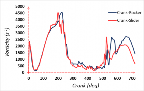
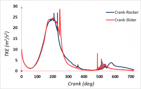
Vorticity is higher in case of crank-rocker engine just before the power stroke begins. The spark is supposed to ignite at around 360° CA just before the piston reaches TDC. At this point, the vorticity and TKE of crank-rocker engine is seen significantly higher than in case of crank-slider engine. Almost 100% increase is recorded for C-R engine at 360° CA, just before the spark, in terms of vorticity and turbulent kinetic energy trends as shown in Figure 10.
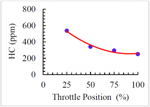
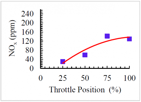
According to previous researchers [9, 26, 27], the higher the vorticity and TKE in the cylinder, the greater the thorough mixing, efficient combustion, and thus minimum emissions. This analytical result can be validated with the experimental findings of C-R engine for combustion emissions (Figure 11).
(a)
(b)
Figure 9. (a) Cylinder pressure and (b) Dynamic viscosity trend of crank-rocker and crank-slider engine at cold-flow conditions
(a)
(b)
Figure 10. (a) Vorticity and (b) Turbulent kinetic energy trend within the cylinders of crank-rocker and crank-slider engine at cold-flow conditions
(a)
(b)
Figure 11. Experimental emissions analysis for (a) HC and (b) NOX of crank-rocker engine [24]
Different configurations of engines are being developed to make commercial engines as efficient as possible. For this purpose, a novel crank-rocker (C-R) engine was designed, fabricated, and performance tested in Universiti Teknologi PETRONAS (UTP). This engine is a type of toroidal engine and is novel in terms of the piston displacement in a curved combustion chamber, which is a rocking motion instead of the sliding one, and thus has lower frictional losses as compared to the conventional crank-slider engines. This research focuses on the comparison between the crank-rocker and conventional crank-slider engine in terms of airflow and turbulent characteristics. For this purpose, CAD models of the crank-rocker and the corresponding crank-slider engines combustion chambers were developed for the numerical analysis of airflow within both engines.
This paper shows the comparison of CFD analysis of airflow through two-valve single-cylinder crank-rocker engine and the crank-slider engine, both operated at standard temperature and pressure and at cold-flow conditions. A full hydrodynamic transient simulation with compressible gas flow solver was initialized and RNG k-ε turbulence model was used to define the airflow. The flow velocity vectors were generated in the post-processing of solver while the trends of tumble & swirl ratios, cylinder pressure, TKE, turbulent dynamic viscosity and vorticity were generated.
Following are the key findings and advantages of C-R engine over the conventional crank-slider engines:
The engine under study can be used as a replacement for the current crank-slider engines in automotive industry due to an overall increased turbulent behaviour, better air-fuel mixing, combustion, and engine efficiency. The implication of this study is that the crank-rocker engine can be used in hybrid/biofuel-based vehicles. The reason for this is that even though the biofuel itself has lower combustion efficiency, the crank-rocker engine can compensate for it and can give better performance for biofuel as compared to the conventional engine. Future research works include the development of multi-cylinder crank-rocker engines and their performance testing for different fuel types.
The authors hereby acknowledge financial support from Yayasan Universiti Teknologi PETRONAS (YUTP) Malaysia in lieu of Graduate Research Assistantship (GRA) Scheme under the grant cost centre: 015LC0-127.
|
C-R |
Crank-Rocker |
|
CFD |
Computational Fluid Dynamics |
|
UTP |
Universiti Teknologi PETRONAS |
|
RNG |
Re-Normalization Group |
|
TKE |
Turbulent Kinetic Energy |
|
IC |
Internal Combustion |
|
RANS |
Reynold’s Averaged Navier-Stokes |
|
TI |
Turbulent Intensity |
|
CAD |
Computer-Aided Design |
|
CPU |
Central Processing Unit |
|
AMR |
Adaptive Mesh Refinement |
|
bTDC |
Before Top Dead Centre |
|
aBDC |
After Bottom Dead Centre |
|
CA |
Crank Angle |
|
Greek symbols |
|
|
ε |
Transported variable rate of dissipation of turbulent kinetic energy |
|
vo |
Molecular kinematic viscosity |
|
ρ |
Density |
|
ω |
Angular velocity |
|
$\mu$ |
Eddy viscosity |
[1] Buhl, S., Hartmann, F., Kaiser, S.A., Hasse, C. (2017). Investigation of an IC engine intake flow based on highly resolved LES and PIV. Oil & Gas Science and Technology – Revue d’IFP Energies Nouvelles, 72(3): 15. https://doi.org/10.2516/ogst/2017012
[2] Jamil, A., Baharom, M.B., Aziz, A.R.A. (2021). IC engine in-cylinder cold-flow analysis – A critical review. Alexandria Engineering Journal, 60(3): 2921-2945. https://doi.org/10.1016/j.aej.2021.01.040
[3] Cao, J., Ma, Z., Li, X., Xu, M. (2019). 3D proper orthogonal decomposition analysis of engine in-cylinder velocity fields. Measurement Science and Technology, 30(8). https://doi.org/10.1088/1361-6501/ab25c1
[4] Yang, J., Dong, X., Wu, Q., Xu, M. (2019). Effects of enhanced tumble ratios on the in-cylinder performance of a gasoline direct injection optical engine. Applied Energy, 236: 137-146. https://doi.org/10.1016/j.apenergy.2018.11.059
[5] El-Adawy, M., Heikal, M.R., Aziz, A.R.A., Siddiqui, M.I., Munir, S. (2017). Characterization of the inlet port flow under steady-state conditions using PIV and POD. Energies, 10(12): 1-16. https://doi.org/10.3390/en10121950
[6] Shafie, N.A.M., Said, M.F.M. (2017). Cold flow analysis on internal combustion engine with different piston bowl configurations. Journal of Engineering Science and Technology, 12(4): 1048-1066.
[7] Stiehl, R., Bode, J., Schorr, J., Krüger, C., Dreizler, A., Böhm, B. (2016). Influence of intake geometry variations on in-cylinder flow and flow – spray interactions in a stratified direct-injection spark-ignition engine captured by time-resolved particle image velocimetry. International Journal of Engine Research, 17(9): 983-997. https://doi.org/10.1177/1468087416633541
[8] Krishna, B.M., Mallikarjuna, J.M. (2009). Tumble flow analysis in an unfired engine using particle image velocimetry. World Academy of Science, Engineering and Technology, International Journal of Mechanical, Aerospace, Industrial, Mechatronic and Manufacturing Engineering, 3: 706-711.
[9] Clark, L.G., Kook, S., Chan, Q.N., Hawkes, E. (2018). The effect of fuel-injection timing on in-cylinder flow and combustion performance in a Spark-Ignition Direct-Injection (SIDI) engine using Particle Image Velocimetry (PIV). Flow, Turbulence and Combustion, 101: 191-218. https://doi.org/10.1007/s10494-017-9887-x
[10] Nishad, K., Ries, F., Li, Y., Sadiki, A. (2019). Numerical investigation of flow through a valve during charge intake in a DISI -engine using large eddy simulation. Energies, 12(13). https://doi.org/10.3390/en12132620
[11] Singh, A., Poonia, S., Jalan, A., Singh, J., Kumar, N. (2019). Intake and exhaust ports design for tumble and mass flow rate improvements in gasoline engine. SAE Technical Paper 2019-01-0763. https://doi.org/10.4271/2019-01-0763
[12] Anbese, Y.T., Aziz, A.R.A., Heikal, M.R. (2012). Characteristics of induction flow in SI direct injection engine with dual variable swirl control valve. Journal of Applied Sciences, 12(24): 2534-2540. https://doi.org/10.3923/jas.2012.2534.2540
[13] Krishna, A.S., Mallikarjuna, J.M., Kumar, D. (2016). Effect of engine parameters on in-cylinder flows in a two-stroke gasoline direct injection engine. Applied Energy, 176: 282-294. https://doi.org/10.1016/j.apenergy.2016.05.067
[14] Paul, B., Ganesan, V. (2010). Flow field development in a direct injection diesel engine with different manifolds. International Journal of Engineering, Science and Technology, 2(1): 80-91.
[15] Amrouche, F., Erickson, P., Park, J., Varnhagen, S. (2014). An experimental investigation of hydrogen-enriched gasoline in a Wankel rotary engine. Int. J. Hydrogen Energy, 39(16): 8525-8534. https://doi.org/10.1016/j.ijhydene.2014.03.172
[16] Szymkowiak, M., Szwaja, S. (2015). New concept of a rocker engine –– kinematic analysis. J. KONES. Powertrain Transp. 19(3): 443-449. https://doi.org/10.5604/12314005.1138160
[17] Holland, R.A. (2015). Opposed Piston Engine. United State Patent 20150300241, Filed Oct 22, 2015.
[18] Mohammed, S.E., Baharom, M.B., Aziz, A.R.A. (2017). Performance and combustion characteristics of a novel crank-rocker engine. Journal of Mechanical Science and Technology, 31(7): 3563-3571. https://doi.org/10.1007/s12206-017-0643-x
[19] Singh, A.P., Gadekar, S., Agarwal, A.K. (2016). In-cylinder air-flow characteristics using tomographic PIV at different engine speeds , intake air temperatures and intake valve deactivation in a single cylinder optical research engine. SAE Technical Paper 2016-28-0001. https://doi.org/10.4271/2016-28-0001
[20] Wang, T., Li, W., Jia, M., Liu, D., Qin, W., Zhang, X. (2015). Large-eddy simulation of in-cylinder flow in a DISI engine with charge motion control valve: Proper orthogonal decomposition analysis and cyclic variation. Applied Thermal Engineering, 75: 561-574. https://doi.org/10.1016/j.applthermaleng.2014.10.081
[21] Toh, H.T., Huang, R.F., Lin, K.H., Chern, M.J. (2011). Computational study on the effect of inlet port configuration on in-cylinder flow of a motored four-valve internal combustion engine. Journal of Energy Engineering, 137(4): 198-206. https://doi.org/10.1061/(ASCE)EY.1943-7897.0000044
[22] Mohammed, S.E., Baharom, M.B., Abd Aziz, A.R., Zainal A., E.Z. (2019). Modelling of combustion characteristics of a single curved-cylinder spark-ignition crank-rocker engine. Energies, 12(17): 3313. https://doi.org/10.3390/en12173313
[23] Jemni, M.A., Kantchev, G., Abid, M.S. (2011). Influence of intake manifold design on in-cylinder flow and engine performances in a bus diesel engine converted to LPG gas fuelled, using CFD analyses and experimental investigations. Energy, 36(5): 2701-2715. https://doi.org/10.1016/j.energy.2011.02.011
[24] Mohammed, S.E., Baharom, M.B., Aziz, A.R.A., Zainal, E.Z., Firmansyah, F. (2018). Experimental investigation of ignition timing on the performance and emission characteristics of a crank-rocker engine. Int. J. Veh. Struct. Syst. 10(2): 146-149. https://doi.org/10.4273/ijvss.10.2.14
[25] da Costa, R.B.R., Braga, R.M., Gomes Júnior, C.A., Valle, R.M., Huebner, R. (2017). PIV measurements and numerical analysis of in-cylinder tumble flow in a motored engine. Journal of the Brazilian Society of Mechanical Sciences and Engineering, 39(10): 3931-3945. https://doi.org/10.1007/s40430-017-0878-6
[26] Lee, K., Bae, C., Kang, K. (2007). The effects of tumble and swirl flows on flame propagation in a four-valve S.I. engine. Appl. Therm. Eng., 27(11-12): 2122-2130. https://doi.org/10.1016/j.applthermaleng.2006.11.011
[27] Bücker, I., Karhoff, D.C., Klaas, M., Schröder, W. (2012). Stereoscopic multi-planar PIV measurements of in-cylinder tumbling flow. Exp. Fluids., 53(6): 1993-2009. https://doi.org/10.1007/s00348-012-1402-5