Nour El Houda Dehimi*![]() | Zakaria Tolba
| Zakaria Tolba![]() | Nassima Djabelkhir
| Nassima Djabelkhir
© 2024 The authors. This article is published by IIETA and is licensed under the CC BY 4.0 license (http://creativecommons.org/licenses/by/4.0/).
OPEN ACCESS
In this paper, we propose a novel model-based testing approach designed to consider the nuances of interactions among agents, allowing for inclusive, exclusive, or parallel execution. The aim is to prevent the activation of multiple behavioural scenarios during the testing of a specific scenario, ensuring that each detected error is uniquely associated with the tested scenario and not influenced by parallel scenarios. This approach involves generating a set of individual test cases that individually cover the interactions of the scenario under test. To achieve this purpose, the approach uses the AUML sequence diagram as a model and the constraints, expressed in object constraint language (OCL), necessary for the execution of each interaction to introduce plugs. These plugs must be able to eliminate from the interval of the test case inputs, compatible with the execution constraints of the interactions of the scenario under test, the part of the inputs compatible with the execution constraints of the other interactions that can be executed in parallel inclusively or exclusively with the interactions of the same scenario. The proposed approach is supported by a formal framework and applied to a concrete case study to illustrate its usefulness.
multi-agent systems (MAS), model-based testing (MBT), test case, AUML sequence diagram, object constraint language (OCL)
A multi-agent system (MAS) is a computational system composed of multiple interacting autonomous entities called agents. Each agent operates independently, making decisions and taking actions to achieve its goals, often in a dynamic and uncertain environment. The distinctive functional and behavioural characteristics of MAS, such as autonomy and proactivity, and the concept of organisation, which are still relatively new, have made it possible to model and develop many complex systems, where the interactions among agents give rise to emergent behaviors that may not be apparent from the individual behaviors of the agents [1]. These new features pave the way for research in a variety of domains at various design stages, particularly software testing. Testing multi-agent systems presents a complex challenge, primarily due to several factors. These include the simultaneous and independent operation of multiple agents, the manipulation of substantial amounts of data by each agent, each with its own set of goals, the unpredictable evolution of the system's behaviour, the non-reproducible effect where identical input data may not guarantee identical states in different executions, the autonomy of agents, and the escalating complexity inherent in the distributed nature of applications comprising multiple components. Moreover, interactions between agents can occur inclusively, exclusively, or in parallel, leading to the simultaneous execution of various behavioural scenarios. This complicates the testing phase, making it difficult to generate test cases that exclusively cover the interactions of the targeted scenario. Consequently, ensuring that each identified error in a specific scenario is not linked to another scenario running concurrently becomes a formidable task. In the existing literature, there are relatively few studies on MAS testing. Notably, the previous studies [2-6] focus on the unit testing level; the researches [7-13] address the agent testing level; the researches [14-17] explore multiple testing levels; and the researches [18-22] concern the system testing level. However, these studies have not adequately addressed the unique aspects of interactions between agents, which can occur inclusively, exclusively, or concurrently.
Testing scenarios individually requires the generation of a set of test cases, composed of test case inputs and test case outputs, where the inputs must be compatible only with the execution constraints of the interactions of the scenario under test. These inputs must not be compatible with the execution constraints of the other interactions that can be executed in parallel inclusively or exclusively, with the interactions of this scenario. To do this, it suffices to introduce, for each interaction involved in a given scenario under test, plugs able to eliminate, from the interval of inputs compatible with the execution constraint of the interactions of the scenario under test, the part of the inputs compatible with the execution constraints of the other interactions able to be executed in parallel inclusively or exclusively with the interactions of this scenario. This represents the central idea of the proposed approach.
We present in this paper a novel MBT approach designed for testing interactions among agents in a multi-agent system [23, 24]. The aim is to guarantee that, during the testing of a specific scenario, no multiple behavioural scenarios are triggered, and any identified errors are not interconnected with concurrently running scenarios. For this purpose, we use: (i) the AUML sequence diagram as a model to systematically generate test cases, thus ensuring complete coverage of the system's various interactions and scenarios; (ii) the constraints, expressed in OCL, necessary for the execution of each interaction in order to introduce plugs, thus generating test cases capable of avoiding the problem of several behaviour scenarios being triggered simultaneously during testing. This allows the approach to take into account the particularities of interactions between agents, which can be conducted exclusively, inclusively or in parallel. Furthermore, it also improves test coverage, facilitates early detection of errors and streamlines test process automation.
The rest of this paper is divided into the following sections. A brief synopsis of major-related work is presented in Section 2. The basic concept of MBT is presented in Section 3. In Section 4, the proposed approach is explained. A specific case study is used in Section 5 to demonstrate the suggested strategy. In Section 6, several conclusions and additional ramifications are provided.
In the literature, there have been relatively few approaches proposed for testing Multi-Agent Systems in recent years. The following section outlines some of the selected approaches:
Núñez et al. [3] presented a formal framework for delineating the behaviour of autonomous e-commerce agents. The anticipated behaviours of the agents undergoing testing are expressed through a novel formalism known as the utility state machine, which embeds users' preferences within its states. The paper introduces two testing methodologies for assessing whether an implementation of a specified agent behaves as expected, i.e., conformance testing—one active and the other passive. In the active testing approach, a dedicated test agent is employed for each agent under scrutiny. This test agent, acting as a special agent, utilizes the formal specification of the agent to guide it toward a specific state. The operational trace of the agent is then compared to the specification to identify any faults. The authors also advocate passive testing, where the agents under examination are solely observed without simulation, as is done in active testing. Any invalid traces are subsequently pinpointed through the formal specifications of the agents.
Thangarajah et al. [6] introduced a technique to gauge the degree of completion of goals within a BDI (belief, desire, and intention) agent system. The evaluation of completeness considers the resources utilized to attain a goal and assesses the impact of goals in relation to the achieved desired results. Goals completion is measured based on efforts expended, successes achieved, the agent's inactivity, and the time needed for the action. The authors embraced the concept of a goal-plan tree, where goals are annotated with relevant plans to create a tree structure.
In study of Nguyen et al. [10], the authors introduced and evaluated a technique for examining autonomous agents which generates demanding test scenarios through evolutionary optimization. This paper outlined a systematic procedure for evaluating the quality of autonomous agents. Initially, stakeholder requirements are identified as quality metrics, and their associated thresholds are subsequently utilized as testing criteria. Fulfilling these requirements is crucial for ensuring the reliability of autonomous agents. The evolutionary test generation method employs fitness functions aligned with testing objectives to automatically generate test cases.
Abushark et al. [11] formulated an approach to detect design flaws in agent designs by scrutinizing the plan structure against specified requirements. Utilizing Prometheus design files, including the goal overview and scenario diagram, the authors transformed these design models into Petri nets. They employed agent role grouping and agent design to generate a plan graph, from which plan traces were extracted and analyzed using Petri nets. Furthermore, a comparative report was generated, and the validation process yielded 21 plan graphs.
In study of Nguyen et al. [14], Goal-Oriented Software Testing (GOST), a thorough testing technique, was suggested. In order to generate test suites at all testing levels, from unit to acceptance, goal-oriented analysis and design was used. GOST offers a model of the testing process that makes the relationships between goals and test cases apparent, and outlines a systematic methodology for generating test cases from goal analysis. By doing so, errors may be found early on and incorrect requirements may not be implemented. Additionally, GOST includes a tool that facilitates the creation, design, and execution of test cases.
Barnier et al. [15] compared multi-agent system testing and software testing in an embedded context. The AEIO aspects for multi-agent systems were used to analyse key multi-agent system testing approaches in this work. In order to test MAS on embedded systems, a specific methodology was to be provided. Agent test, collective resource test, and acceptance test are the three fundamental levels on which the suggested methodology was developed.
Nguyen et al. [13] presented a method for testing autonomous agents employing evolutionary optimization to create challenging test cases. The authors introduced a systematic approach to assess the effectiveness of autonomous agents. Initially, stakeholder requirements are translated into quality measures, and associated thresholds serve as testing criteria. The reliability of autonomous agents is contingent upon meeting these criteria. Corresponding fitness functions outlining testing objectives are defined to guide the evolutionary test generation technique in the automatic creation of test cases.
In studies of El Houda Dehimi [18] and Dehimi et al. [19], we propose a new model-based testing method for holonic agents. The method makes use of genetic algorithms and considers an agent's evolution (successive versions). The strategy is divided into two key iterative phases. A new version of an agent that is being tested must be found during the first phase. The testing of each recently discovered version is covered in the second step. To create a behavioural model that is based on the creation of test cases, the new version of the agent is examined. The process of creating test cases concentrates on the new (and/or modified) facets of the agent behaviour. In this approach, the technique provides an incremental update of the test cases, which is a critical issue.
Gonçalves et al. [20] provided a thorough technique using the Moise+ organisational model for analysing and rating the social level of the MAS. This framework uses a Moise+ requirements set as an information artefact mapped in the CPN4M coloured Petri net model to generate test cases. The test adequacy criteria used by CPN4M are all-paths and statetransition path. The shift from Moise+ to CPN has been documented in this work, along with the processes for creating test cases and running several tests in a case study. The findings show that this methodology can improve the degree of social level adjustment in a Moise+ model-specified multi-agent system, highlighting the system context that may cause the MAS to fail.
In study of Dehimi et al. [21], we propose a new method of producing test cases that can account for various behavioural situations in a multi-agent system. The goal is to locate the scenario that generated the detected error among the parallel scenarios in the event that an error is identified. In order to accomplish this, the method first uses mutation analysis and parallel genetic algorithms to pinpoint the instances of the agents performing the interactions shown in the sequence diagram of the test scenario, and only those instances will be used as inputs in the test case. The second part of the technique involves identifying the expected outputs of the test case based on its inputs, using the activities shown in the activity diagram.
In study of El Houda et al. [22], we propose a novel approach for generating test cases that consider emerging interactions stemming from the unpredictable behaviour of MAS undergoing testing. This method involves dynamically applying a model-based test to each new iteration of the system in question. It achieves this by: (i) utilizing the AUML sequence diagram of each updated version of the system to create test cases that encompass the new interactions introduced; (ii) incorporating constraints articulated in OCL, essential for executing each interaction to accommodate the intricacies of inclusive, exclusive, or parallel interactions between agents; and (iii) employing genetic algorithms to adhere to the rules governing each interaction.
These works greatly advanced the field by introducing novel MAS test methods, but they did not sufficiently address the tests of interactions between agents that can be conducted inclusively, exclusively, or in parallel. As a result, these approaches can detect errors, but they cannot accurately determine the origin of these errors, which complicates the error correction phase. In this paper, we introduce a novel test case generation method based on the AUML sequence diagram that can account for the particularities of interactions between agents, which can be carried out inclusively, exclusively, or concurrently. The main objective is to ensure that no multiple behaviour scenarios are activated when testing a particular scenario, and that any errors discovered during testing a particular scenario are unrelated to any other scenarios that may be running concurrently.
Model-Based Testing is an advanced software testing methodology based on the use of formal models to represent the expected behaviour of a system. The main objective of MBT is to automatically generate test cases from these models, thereby ensuring exhaustive and systematic coverage of the functionalities of the system under test. Indeed, by using specialised tools, testers can generate test cases automatically, which considerably reduces manual effort and reduces the risk of human error. This automation also makes it possible to generate a large number of test cases, covering a variety of scenarios, including extreme cases and error situations, which could be overlooked when creating tests manually. In addition, as the models are based on formal system specifications, the tests generated are perfectly consistent with the expectations defined, ensuring rigorous validation of the requirements. MBT is also highly beneficial in terms of maintenance. Software systems often evolve, with frequent updates and changes to functionality. With traditional testing methods, this means manually rewriting the test cases for each change, which can be tedious and error-prone. With MBT, on the other hand, it is simply a question of updating the model to reflect the new specifications. Test cases can then be regenerated automatically from the updated model, ensuring that tests remain aligned with the new system requirements without the need for exhaustive rewriting of test scripts. MBT involves several steps to ensure rigorous and systematic validation of software systems. The first step is to create a formal model that represents the expected behaviour of the system. This model can be a finite state machine, a sequence diagram, or any other type of formal representation adapted to the system's specifications. Next, the test cases are generated from this model. Specialised tools are often used to automate this stage, enabling tests to be created covering a wide range of possible scenarios, including those that are difficult to predict manually. The third stage is the execution of the generated tests on the real system or a simulation. This involves comparing the results obtained with the expectations defined in the model to identify any discrepancies. Finally, the analysis of the results enables anomalies to be detected and the compliance of the system with the specifications to be verified. If faults are found, the model and test cases can be updated accordingly, and the tests rerun. These iterative steps ensure exhaustive coverage and ongoing quality of the system under test.
MBT is particularly useful for MAS because of the complexity and dynamics of their interactions. In MAS, autonomous agents interact in often unpredictable ways to achieve specific goals or common goals, creating a multitude of possible execution scenarios. MBT allows these interactions and behaviours to be formally modelled, facilitating the automatic generation of exhaustive test cases. This makes it possible to cover a wide range of situations, including rare scenarios and exception behaviours that are difficult to anticipate manually. Using this approach, it is possible to systematically check the compliance of individual agents and their collective interactions with the specifications in various situations. In addition, the ability to easily update models to reflect unpredictable changes in MAS behaviour ensures that tests remain pertinent, making it easier to cover new system behaviours. In this way, MBT offers a powerful solution for successfully managing the complexity of multi-agent systems, guaranteeing better quality and reliability of the final system.
The proposed approach involves creating a set of test cases based on an AUML sequence diagram, aiming to cover each scenario independently. To achieve this, the approach introduces plugs for every interaction associated with a specific scenario being tested. The plugs are able to eliminate, from the interval of inputs compatible with the execution constraint of the interactions of this scenario, the part of the inputs compatible with the execution constraints of the other interactions involved in the other scenario that can be executed in parallel, inclusively, or exclusively with the interactions of the scenario under test. This avoids the triggering of the execution of several scenarios with the scenario under test, and ensures that each error detected during the test of a given scenario is not associated with another scenario that can be running in parallel with it.
The approach collects, in the first stage, the information necessary for the execution of each interaction (presented in the AUML sequences diagram), namely the execution constraints of each interaction (expressed in OCL), the range of inputs, and the expected outputs of the task that will be executed following each interaction, etc. In the second stage, the approach applies an algorithm that is able to recalculate the execution constraints (collected in the first stage) of each interaction. This is to obtain, for each interaction, a new execution constraint that contradicts the execution constraints of the other interactions that can be performed inclusively, exclusively, or in parallel with it. The sub-interval of inputs (included in the global range of inputs collected in the first stage) compatible with each new constraint only ensures the triggering of the execution of the desired interaction. Consequently, the union of the sub-intervals of the interactions of a given scenario under test ensures the triggering of this scenario only, which ensures an individual test for the latter. These sub-intervals will be considered as test case inputs and can be retrieved from the information already collected. They will be used, with their expected outputs, subsequently, for the detection of possible errors.
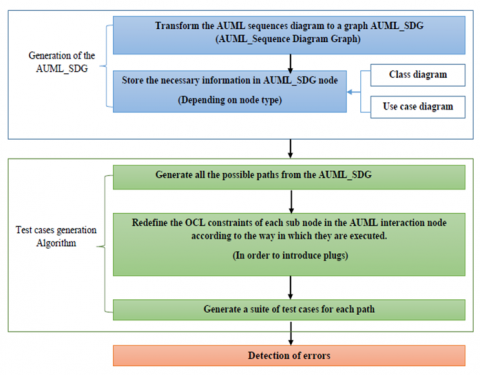
The approach is divided into three phases (Figure 1).
Figure 1. The methodology of the proposed approach
Transformation of the AUML sequence diagram into a graph: To automate the phases within our approach, we employed the AUML sequence diagram to create an AUML_SDG graph (AUML Sequence Diagram Graph). In this graph, each path Pk represents a scenario Scek in the sequence diagram, for which we must find the inputs Inputskthat ensure the execution of the interactions of this scenario only, and the outputs Outputsk expected for these inputs. Each interaction between two agents in the AUML sequence diagram is represented by a node (Interaction node type) in the graph AUML_SDG that contains the set of information, collected from the class diagram and used case diagram, necessary for the generation of test cases namely: the execution constraints of each interaction (expressed in OCL), the range of inputs, and the expected outputs of the task that will be executed following each interaction, etc. The interaction nodes that can be executed inclusively, exclusively, or in parallel are grouped in another node, an AUML node type. The latter contains information on how its interaction nodes (sub-nodes) are executed (inclusively, exclusively, in parallel). This information collected from the AUML sequences diagram is necessary for the generation of plugs.
Generation of test cases: In this phase, we have proposed an algorithm to generate a set of test cases (composed of input of test cases and expected outputs) from the graph AUML_SDG generated in the first phase. These test cases are able to cover all the paths of the graph individually. This is ensured by: (i) redefining the constraints expressed in OCL of each sub-node in the AUML nodes of each path; this redefinition depends on how the subs interactions of these nodes are executed; (ii) retrieving, from the information already collected, the sub-interval of inputs that is compatible only with the redefined constraints. This sub-interval will be considered as test case inputs and their expected outputs will be considered as test case outputs.
(3) Detection of errors: following the generation of test cases, the error detection phase begins to identify interaction and scenario errors. To achieve this, we execute the agents of the system under test using the inputs of the test cases, and subsequently compare the obtained results with the expected ones.
The proposed algorithm for the generation of test cases is described, together with a formal definition of the proposed graph and a description of the error detection phase, in the sections that follow.
4.1 The formal definition of the AUML_SDG
AUML_SDG= {Int_N, AUML_N, E, S0, Sf}, where,
E is the set of transitions from one state to another.
S0 is the initial node. It contains the Pre-conditions that trigger all possible scenarios in the AUML_SDG. This information is obtained from the use case diagram.
Sf is the set of final nodes. It contains the post-condition associated with the possible scenarios. This information is obtained from the use case diagram.
Int_N is a set of simple interaction nodes. Each node S_Inti $\in$ Int_N is defined as follows: S_Inti = {mi, from_Agent, to_Agent, inf_Inti}, where, mi is the name of the message, from_Agent is the sender of the message, to_Agent is the receiver of the message, inf_Inti is a set of information on the interactions represented by the node S_Inti. It is defined as follows: Inf_Inti = {R_Inputsi, Outputsi, Guard_conditioni} where,
(1) R_Inputsi: represents the range of inputs of the tasks that will be executed following the interaction represented by the node. This information is collected from the class diagram and from constraints, expressed in OCL, specified in the corresponding task in the class diagram.
(2) Outputsi: represents the expected outputs of the tasks that will be executed following the interaction represented by the node. Theseinformation are collected from the class diagram and from the use case diagram.
(3) Guard_conditioni: is the constraints necessary for the execution of the interaction of the node S_Inti. This information is collected from constraints, expressed in OCL, specified in the sequences diagram.
(4) AUML_N is a set of interaction nodes that can be executed inclusively, exclusively, or in parallel. Each node S_AUMLi Î AUML_N is defined as follows: S_AUMLi = {Set_Ni, Inf_AUMLi}, where, Set_Ni represents a set of sub-node of the node S_AUMLi. Each node Sj Î Set_Ni can be an Int_N or AUML_N, Inf_AUMLi is a set of information on S_AUMLi node. It is defined as follows: Inf_AUMLi= {Modei, Guard_conditioni}, where,
(1) Modei represents the way in which the sub-nodes Sj of the nodes S_AUMLj are executed. This information can take the following values Inclusive, Exclusive, or Parallel. It is collected from the AUML sequences diagram.
(2) Guard_conditioni is the constraint necessary for the execution of the interaction of the node S_AUMLi. This information is collected from constraints, expressed in OCL, specified in the sequences diagram. The guard condition of each sub-node Sj of the nodes S_AUMLj will be redefined according to the Modei of S_AUMLi, where,
If Modei = Inclusive then Sj.Guard_condition = (Sj.Guard_condition $\cup$ S_AUMLi.Guard_condition) $\cup$ ($\cup$ ! Sm.Guard_condition ) where: Sm {Set_Ni – Sj},
If Modei = Exclusive then Sj.Guard_condition = (Sj.Guard_condition ($\cup$S_AUMLi.Guard_condition) ∩ ($\cup$Sm.Guard_condition) where: Sm = {Set_Ni - Sj},
If Modei = Parallel then Sj.Guard_condition = S_AUMLi.Guard_condition$\cup$ ($\cup$ !Sm.next.Guard_condition) where, Sm = {Set_Ni - Sj}.
4.2 The algorithm of the test cases generation
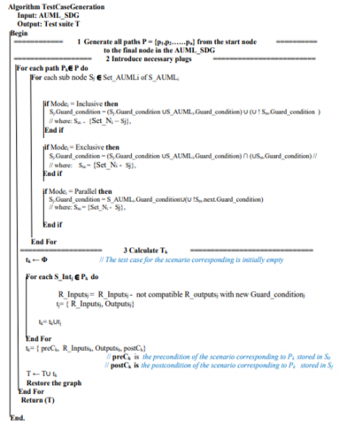
The set of test cases T that can cover all potential paths in the AUML_SDG can be calculated using the algorithm for test case creation (Figure 2). The algorithm does this by doing the following steps:
Figure 2. The algorithm used to generate test cases
-The generation of all possible paths Pk from the AUML_SDG.
-For each Sj in the path Pk where Sj is a sub-interaction node of an AUML_N node S_AUMLi, the algorithm recalculates its guard conditions according to Modei of S_AUMLi in order to introduce necessary plugs.
-After redefining the guard condition, the algorithm calculates the set of test cases Tk of the path Pk. For this the algorithm retrieves, from each Int_N S_Intj, the Range of inputs R_Inputsj stored in the nodes of the path Pk, which is compatible with the new guard condition.
When the test cases generation algorithm is applied to an AUML SDG, a set of test cases T that may independently cover each path of the AUML SDG is obtained. Each resulting test case includes a set of inputs that can cover the desired path (pk) as well as a set of expected outputs when the agents are run with these inputs. It also includes the precondition required to execute the path (pk) and the anticipated postcondition upon executing the test case's inputs on the system under test's agents. The second part of the algorithm, which consists of redefining the guard conditions in order to introduce plugs, is best illustrated by the following example:
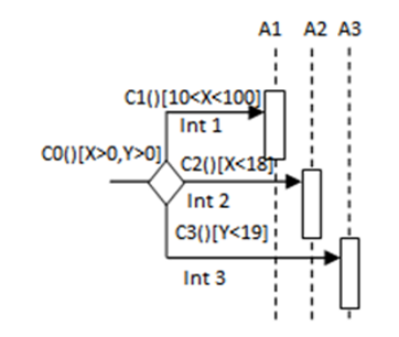
To cover the interaction Int1 (Figure 3), it is crucial to adhere to the guard conditions C0 and C1. To achieve this, it is essential that the values of X fall within the range of 10 to 100, and Y is greater than 0. By doing so, during the error detection phase, when executing agents with inputs falling within these specified intervals, the agent can successfully perform other interactions, namely Int2 and Int3. This is because the inputs used for agent execution do not conflict with the guard conditions of the other interactions, preventing any deviation from the desired testing path that includes Int1.
Figure 3. Inclusive interaction
To prevent such deviation, it is necessary to redefine the guard conditions C1. This involves transforming them into C1 = C0 $\cup$ C1 $\cup$ (!C2 $\cup$ !C3). Consequently, the new conditions require that X is in the range of 18 to 100, and Y is greater than 19. This adjustment ensures that the inputs used for agent execution exclusively cover the interaction Int1. As a result, any errors detected in a particular scenario are not associated with another scenario executed concurrently or in parallel, maintaining the desired testing focus.
4.3 Detection of errors
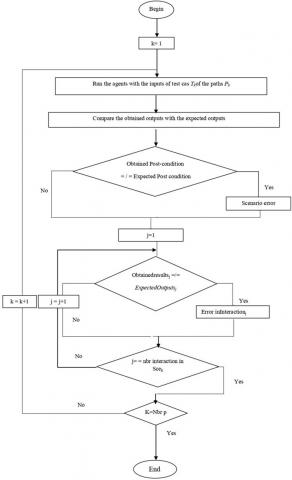
For error detection, it is sufficient to compare (for each path Pk) the expected outputs and the outputs attained after the agents' execution. There may be an interaction error if the obtained results do not match the expected ones, and there may be a scenario error if the obtained post-condition does not match the expected one. Figure 4 summarizes the error detection process.
Figure 4. Error detection process
To validate our approach, we apply it to a concrete case study involving a Planning and Distribution System (PDS). The PDS is designed to optimize the logistics of transporting goods by assigning driver agents to deliver specific quantities of products to designated points (xi). These points are located within specified geographic zones, which can include zone A, zone B, or a combination of both (xi $\in$ A or xi $\in$ B or xi $\in$ A $\in$ B). The actors involved in this system are:
Agent GUI: represents the interface between the user and the PDS.
Human resource agent: responsible for managing and assigning tasks to the various driver agents, namely the drivers of zone A or B.
Material resource agent: responsible for managing and assigning tasks to the various truck agents, namely light or heavy trucks.
Truck agent: responsible for transport, once the goods are assigned to it depending on the number of goods to be transported; there are two types of trucks, namely:
-Light truck: which transports a number of goods less than or equal to 100 units.
-Heavy truck: which transports a number of goods greater than 100 units.
Driver: responsible for transporting the goods to destination points in zones A or B. There are two types of drivers for this:
-Zone A driver: transports the goods only to destination points belonging to zone A.
-Zone B driver: transports the goods only to destination points belonging to zone B.
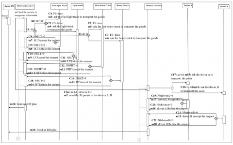
Depending on the overall number of goods to be transported (equal to the sum of the quantities transported to the various points xi), the Material Resource agent sends a request to specialized light or heavy truck agents. These trucks, depending on their availability, can accept or refuse requests from the Material Resource agent. The user has the option of choosing the express service where particular trucks are provided with a high transport capacity in terms of transport time. At the same time, depending on the recipient zone A or B, the Human Resource agent sends a request to zone A driver agents and/or zone B driver agents. These drivers, depending on their availability, can accept or refuse the request. Once the requested quantity is appropriately allocated to trucks and drivers, the material and human resource agents each establish a transport plan.
The transport plan includes the following elements:
The identifier of the zone driver who is responsible for transporting the requested quantity to the destination zones.
The identifier of the light or heavy truck agent who is responsible for transporting the requested quantity.
The quantity to be transported.
The type of transport service selected, namely: Simple or express.
The various parameters linked to the agents themselves, namely the availability of light or heavy truck agents and the availability of drivers.
The AUML SDG graph creation, test case generation, and error detection are the three stages of our technique that are required for testing the PDS system, and we will detail each of these in the sections that follow. Following the usage of a software tool that we have built, the findings shown in each phase are obtained automatically.
5.1 Generation of the AUML_SDG graph from the AUML sequence diagram
The generation of the AUML_SDG graph represents the first step in the process of generating the test cases. It is done automatically based on the three AUML diagrams involved in the modelling of the system studied, namely the AUML sequence diagram (Figure 5) for the creation of the various nodes of the AUML_SDG graph (the simple nodes and the AUML nodes), Use Case Diagram (Figure 6), and Agent Class Diagram (Figure 7) for the filling of the nodes by the necessary information during the generation of the test cases.
Figure 5. Sequence diagram of the "PDS"
Figure 6. Use case diagram of the "PDS"
Figure 7. Class diagram of the PDS
The generation of the AUML_SDG graph goes through an intermediate step which consists of transforming, first of all, the sequence diagram, use case diagram, and agent class diagram into an XML file. The purpose of this is to simplify the creation and the filling of the various nodes of the graph.
Figure 8 represents the generated AUML_SDG graph, each node of which represents an interaction. It contains all the information necessary for the generation of test cases. All nodes in a dotted circle are nodes included in an AUML type node (an AUML interaction) where the blue node represents parallel interactions, the green node represents inclusive interactions, and the red nodes represent exclusives interactions.
Figure 8. The generated AUML_SDG graph
5.2 Test case generation
In this phase, the test case generation algorithm is applied to the generated AUML_SDG. Table 1 represents the generated paths from the graph AUML_SDG. Each path Pk of the graph G represents a possible behaviour scenario Scek for the system under test.
Table 1. Generated paths (all paths)
|
All Paths |
Generated Paths |
|||||
|
Sce 1 |
Initial |
S2: (m2,gui, RH) |
Final_2 |
|
|
|
|
Sce 2 |
Initial |
S2: (m2, GUI, RH) |
S15: (c16, m15, RH, driver) |
S17: (c18, m17, driverA, RH) |
S22: (m22, RH, gui) |
Final_5 |
|
Sce 3 |
Initial |
S2: (m2, GUI, RH) |
S15: (c16, m15, RH, driver) |
S18: (c19, m18, driverA, RH) |
Final_4 |
|
|
Sce 4 |
Initial |
S2: (m2, gui, RH) |
S16: (c17, m16, RH, driverB) |
S19: (c20, m19, driverB, RH) |
S22: (m22, RH, gui) |
Final_5 |
|
Sce 5 |
Initial |
S2: (m2, gui, RH) |
S16: (c17, m16, RH,driver) |
S20: (c21, m20, driverB, R) |
Final_3 |
|
|
Sce 6 |
Initial |
S1: (m1, GUI,RM) |
Final_1 |
|
|
|
|
Sce 7 |
Initial |
S1: (m1,GUI,RM) |
S3: (c4, m3, RM, FLT) |
S7: (c8,m7, FLT,RM ) |
S21: (m21,RM, gui) |
Final_5 |
|
Sce 8 |
Initial |
S1: (m1, GUI,RM) |
S3: (c4, m3, RM,FL) |
S8: (c9, m8,FLT, RM) |
Final_4 |
|
|
Sce 9 |
Initial |
S1: (m1, GUI,RM) |
S4: (c5, m4, RMLT) |
S9: (c10, m9,LT, RM) |
S21: (m21, RM, gui) |
Final_5 |
|
Sce 10 |
Initial |
S1: (m1, GUI, RM) |
S4: (c5, m4, RM, LT) |
S10 (c11, m10, LT, RM) |
Final_4 |
|
|
Sce 11 |
Initial |
S1: (m1, GUI, RM) |
S5: (c6, m5,RM, FHT) |
S11: (c12, m11, FHT, RM) |
S21: (m21, RM, gui) |
Final_5 |
|
Sce 12 |
Initial |
S1: (m1, GUI,RM) |
S5: (c6, m5, RM, FHT ) |
S12: (c13, m12, FHT, RM) |
Final_4 |
|
|
Sce 13 |
Initial |
S1: (m1, GUI,RM) |
S6: (c7,m6, RM,HT) |
S13: (c14, m13, HT, RM) |
S21: (m21, RM, gui) |
Final_5 |
|
Sce 14 |
Initial |
S1: (m1, GUI,RM) |
S6: (c7, m6, RM, HT) |
S14: (c15, m14, HT, RM) |
Final_4 |
|
Table 2. The new guards of the nodes of each path after the introduction of the plugs
|
AUML_N |
New Guards |
AUML_N |
New Guards |
|
P |
S1.guard= Sp. guard∪(!SIn. guard) S2.guard= Sp. guard∪(!SE4. guard) Sp. guard= Ø S1.guard = Ø∪ (xi∉A et/ou xi∉B) S1.guard= xi∉A et/ou xi∉B S2.guard = Ø∪ (∑Q≤100) S2.guard=∑Q≤100 |
E5 |
S9.guard=(S9.guard∪SE5.guard)∩(S10.guard) S10.guard=(S10.guard∪SE5.guard)∩(S9.guard) SE5.guard= Ø S.9guard =(Nb>0∪Ø)∩(Nb<0) S.9guard =(Nb>0∪Ø)∩(Nb<0) S.10guard = (Nb<0∪Ø)∩(Nb>0) S.10guard = (Nb<0∪Ø)∩(Nb>0) |
|
E1 |
S3.guard=(S3.guard∪SE1.guard)∩(S4.guard) S4.guard=(S4.guard∪SE1.guard)∩(S3.guard) SE1.guard= ∑Q<100 S3.guard =(FS=1∪∑Q<100)∩(FS=0) S3.guard= FS=1∪∑Q<100)∩(FS=0) S4.guard = (FS=0∪∑Q<100)∩(FS=1) S3.guard= (FS=1∪∑Q<100)∩(FS=0) S4.guard= FS=0∪∑Q<100)∩(FS=1) |
E6 |
S11.guard=(S11.guard∪SE6.guard)∩(S12.guard) S12.guard=(S12.guard∪SE6.guard)∩(S11.guard) SE6.guard= Ø S11.guard =(Nb>0∪Ø)∩(Nb<0) S.11guard =(Nb>0∪Ø)∩(Nb<0) S12.guard = (Nb<0∪Ø)∩(Nb>0) S.12guard =(Nb<0∪Ø)∩(Nb>0) |
|
E2 |
S5.guard=(S5.guard∪SE2.guard)∩(S6.guard) S6.guard=(S6.guard∪SE2.guard)∩(S5.guard) SE2.guard= ∑Q>100 S5.guard =(FS=1∪∑Q>100)∩(FS=0) S5.guard= FS=1∪∑Q>100∩(FS=0) S6.guard = (FS=0∪∑Q>100)∩(FS=1) S6.guard= FS=0∪∑Q>100∩(FS=1) |
E7 |
S13.guard=(S13.guard∪SE7.guard)∩(S14.guard) S14.guard=(S14.guard∪SE7.guard)∩(S13.guard) SE7.guard= Ø S.13guard =(Nb>0∪Ø)∩(Nb<0) S.14guard = (Nb<0∪Ø)∩(Nb>0) S.13guard =(Nb>0∪Ø)∩(Nb<0) S.14guard =(Nb<0∪Ø)∩(Nb>0) |
|
E3
|
S7.guard=(S7.guard∪SE3.guard)∩(S8.guard) S8.guard=(S8.guard∪SE3.guard)∩(S7.guard) SE3.guard= Ø S.7guard =(Nb>0∪Ø)∩(Nb<0) S7.guard= (Nb>0∪Ø)∩(Nb<0) S.8guard = (Nb<0∪Ø)∩(Nb>0) S8.guard= (Nb<0∪Ø)∩(Nb>0) |
In |
S15.guard=(S15.guard∪SIn.guard)∪(!S16.guard) S16.guard=(S16.guard∪SIn.guard)∪(!S15.guard) SIn.guard= xi∊A et/ou xi∊B S15.guard = (xi∊A ∪ xi∊A et/ou xi∊B) ∪ (xi∉B) S16.guard = (xi∊B ∪ xi∊A et/ou xi∊B) ∩ (xi∉A) |
|
E4 |
SE1.guard=(SE1.guard∪SE4.guard)∩(SE2.guard) SE2.guard=(SE2.guard∪SE4.guard)∩(SE1.guard) SE4.guard= =∑Q≤100 SE1.guard =(∑Q<100∪∑Q≤100)∩(∑Q>100) SE2.guard = (∑Q>100∪∑Q≤100)∩(∑Q<100) |
E8 |
S17.guard=(S17.guard∪SE8.guard)∩(S18.guard) S18.guard=(S18.guard∪SE8.guard)∩(S17.guard) SE8.guard= Ø S.17guard =(Nb>0∪Ø)∩(Nb<0) S.18guard = (Nb<0∪Ø)∩(Nb>0) S.17guard =(Nb>0)∩(Nb<0) S.18guard =(Nb<0)∩(Nb>0) |
|
E9 |
S19.guard=(S19.guard∪SE9.guard)∩(S20.guard) S20.guard=(S20.guard∪SE9.guard)∩(S19.guard) SE9.guard= Ø S.19guard =(Nb>0∪Ø)∩(Nb<0) S.20guard =(Nb<0∪Ø)∩(Nb>0) S.19guard =(Nb>0∪Ø)∩(Nb<0) S.20guard = (Nb<0∪Ø)∩(Nb>0) |
||
After generating all paths from the graph AUML_SDG, the algorithm recalculates the guard conditions of each sub-interaction node Sj (according to Modei of S_AUMLi in which it belongs) in order to introduce the necessary plugs. Table 2 represents the new guards of each sub-interaction node Sj of each path after the introduction of the plugs.
After redefining the guard condition, the algorithm calculates the set of test cases Tk of the path Pk. For this the algorithm retrieves the Range of inputs R_Inputsj stored in the nodes of the path Pk, which is compatible with the new guard condition. Parts 1, 2, and 3 represent the test cases that have been generated.
|
Precondition: The system is ready to receive request
Test case of Scenario_1 (initial/2/final) T_Scenario_1 = {Precondition: The user sends a Request, Input: ∑Q≤0, (Xi not in A) ∩ (Xi not in B), Output: Displays “send the quantity to transported to the trucks”, Displays “not available Xi points”, Displays” RH plan: not available drivers”, Postcondition: Displays” repeat your request”} Possible test case for scenario_1 Case1 Input: quantity1=0, quantity2=0, quantity3=0, (Xi not in A) ∩ (Xi not in B) Output: Displays “send the quantity to transported to the trucks” Displays “don’t send the Xi points to the drivers A, B” Displays “drivers not available” Postcondition: Displays” repeat your request”
Test case of Scenario_2 (initial/2/15/17/22/final) T_Scenario_2 = {Precondition: The user sends a Request, Input: ∑Q≤0, Xi in A, Nbdriver A>0, Output: Displays “send the quantity to transported to the trucks”, Displays “send the Xi points to the drivers A, B”, Displays “send Xi in A”, Displays “driver A accept the request”, Postcondition: Displays “RH plan: driver A is available”} Possible test case for scenario_2 Case1 Input: quantity1=0, quantity2=0, quantity3=0, Xi in A, Nbdriver A>0 Output: Displays “send the quantity to transported to the trucks” Displays “send the Xi points to the drivers A, B” Displays “send Xi in A” Displays “driver A accept the request” Postcondition: Displays “RH plan: driver A is available” Test case of Scenario_3 (initial/2/15/18/final) T_Scenario_3 = {Precondition: The user sends a Request, Input: ∑Q≤0, Xi in A, Nbdriver A<0, Output: Displays “send the quantity to transported to the trucks”, Displays “send the Xi points to the drivers A, B”, Displays “send Xi in A”, Displays” driver A refuse the request Postcondition: Displays “driver A is not available”} Possible test case for scenario_3 Case1 Input: quantity1=0, quantity2=0, quantity3=0, Xi in A, Nbdriver A>0 Output: Displays “send the quantity to transported to the trucks” Displays “send the Xi points to the drivers A, B” Displays “send Xi in A” Displays “driver A refuse the request” Postcondition: Displays “driver A is not available” Test case of Scenario_4 (initial/2/16/19/22/final) T_Scenario_4 = {Precondition: The user sends a Request, Input: ∑Q≤0, Xi in B, Nbdriver B>0, Output: Displays “send the quantity to transported to the trucks”, Displays “send the Xi points to the drivers A, B”, Displays “send Xi in B”, Displays “driver B accept the request”, Postcondition: Displays “RH plan: driver B is available”} Possible test case for scenario_4 Case1 Input: quantity1=0, quantity2=0, quantity3=0, Xi in B, Nbdriver B>0 Output: Displays “send the quantity to transported to the trucks” Displays “send the Xi points to the drivers A, B” Displays “send Xi in B” Displays “driver B accept the request” Postcondition: Displays “RH plan: driver B is available” Test case of Scenario_5 (initial/2/16/20/final) T_Scenario_5 = {Precondition: The user sends a Request, Input: ∑Q≤0, Xi in B, NbdriverB<0, Output: Displays “send the quantity to transported to the trucks”, Displays “send the Xi points to the drivers A, B”, Displays “send Xi in B”, Displays “driver B refuse the request”, Postcondition: Displays “driver B is not available”,} Possible test case for scenario_5 Case1 Input: quantity1=0, quantity2=0, quantity3=0, Xi in A, Nb driver B<0 Output: Displays “send the quantity to transported to the trucks” Displays “send the Xi points to the drivers A, B” Displays “send Xi in B” Displays “driver B refuses the request” Postcondition: Displays “driver B is not available” Test case of Scenario_6 (initial/1/final) T_Scenario_6 = {Precondition: The user sends a Request, Input: ∑Q≤0, (Xi not in A) ∩ (Xi not in B), Output: Displays “send the quantity to transported to the trucks”, Displays “not available Xi points”, Displays” drivers not available”, Postcondition: Displays “repeat your request”} Possible test case for scenario_6 Case1 Input: quantity1=0, quantity2=0, quantity3=0, (Xinot in A) ∩ (Xinot in B) Output: Displays “send the quantity to transported to the trucks” Displays “don’t send the Xi points to the drivers A, B” Displays “quantity not available” Postcondition: Displays “repeat your request” Test case of Scenario_7 (initial/1/3/7/21/final) T_Scenario_7 = {Precondition: The user sends a Request, Input: ∑Q<100,(Xinot in A) ∩ (Xi not in B),FS=true, NbFLT>0, Output: Displays “send the quantity to transported to the trucks”, Displays “don’t send the Xi points to the drivers A,B”, Displays “the fast service is available”, Displays “the fast light truck accept the request”, Postcondition: Displays “RM plan: Fast Light Truck is available”} Possible test case for scenario_7 Case1 Input: quantity1=10, quantity2=50, quantity3=20, FS=true, NbFLT>0 Output: Displays “don’t send the Xi points to the drivers A, B” Displays “the fast service is available” Displays “the fast light truck accept the request” Postcondition: Displays “RM plan: Fast Light Truck is available”}
Test case of Scenario_8 (initial/1/3/8/final) T_Scenario_8 = {Precondition: The user sends a Request, Input: Q<100, (Xinot in A) ∩ (Xinot in B), FS=true, NbFLT<0, Output: Displays “send the quantity to transported to the trucks”, Displays “don’t send the Xi points to the drivers A, B”, Displays “the fast service is available”, Displays “the fast light truck refuse the request”, Postcondition: Displays “Fast Light Truck is not available”} Possible test case for scenario_8 Case1 Input: quantity1=30, quantity2=15, quantity3=25, FS=true, NbFLT<0 Output: Displays “don’t send the Xi points to the drivers A, B” Displays “the fast service is available” Displays “the fast light truck refuse the request” Postcondition: Displays “Fast Light Truck is not available”}
Test case of Scenario_9 (initial/1/4/9/21/final) T_Scenario_9 = {Precondition: The user sends a Request, Input: ∑Q<100, (Xi not in A) ∩ (Xi not in B), FS=false, NbLT>0, Output: Displays “send the quantity to transported to the trucks”, Displays “don’t send the Xi points to the drivers A, B”, Displays “the fast service is not available”, Displays “the light truck accept the request”, Postcondition: Displays “RM plan: Light Truck is available”} Possible test case for scenario_9 Case1 Input: quantity1=5, quantity2=30, quantity3=40, FS=false, NbLT>0 Output: Displays “don’t send the Xi points to the drivers A, B” Displays “the fast service is not available” Displays “the light truck accept the request” Postcondition: Displays “RM plan: Light Truck is available”}
Test case of Scenario_10 (initial/1/4/10/final) T_Scenario_10 = {Precondition: The user sends a Request, Input: Q<100, (Xi not in A) ∩ (Xi not in B),FS=false, NbLT<0, Output: Displays “send the quantity to transported to the trucks ”,Displays ”don’t send the Xi points to the drivers A,B”, Displays “the fast service is not available”, Displays “the light truck refuse the request”, Postcondition: Displays ”Light Truck is not available”} Possible test case for scenario_10 Case1 Input: quantity1=11, quantity2=65, quantity3=18, FS= false, NbLT<0 Output: Displays “don’t send the Xi points to the drivers A, B” Displays “the fast service is not available” Displays “the light truck refuse the request” Postcondition: Displays” Light Truck is not available”} Test case of Scenario_11 (initial/1/5/11/21/final) T_Scenario_11 = {Precondition: The user sends a Request, Input: ∑Q>100,(Xinot in A) ∩ (Xi not in B),FS=true, NbFHT>0, Output: Displays “send the quantity to transported to the trucks”, Displays “don’t send the Xi points to the drivers A,B”, Displays “the fast service is available”, Displays “the fast heavy truck accept the request”, Postcondition: Displays ”RM plan: fast heavy truck is available”} Possible test case for scenario_11 Case1 Input: quantity1=40, quantity2=55, quantity3=60, FS=true, NbFHT>0 Output: Displays “don’t send the Xi points to the drivers A, B” Displays “the fast service is available” Displays “the fast heavy truck accept the request”
Postcondition: Displays “RM plan: fast heavy truck is available”} Test case of Scenario_12 (initial/1/5/12/final) T_Scenario_12 = {Precondition: The user sends a Request, Input: Q>100, (Xi not in A) ∩ (Xi not in B), FS=true, NbFHT<0, Output: Displays “send the quantity to transported to the trucks”, Displays “don’t send the Xi points to the drivers A,B”, Displays “the fast service is available”, Displays “the fast heavy truck refuse the request”, Postcondition: Displays “fast heavy truck is not available”}
Possible test case for scenario_12 Case1 Input: quantity1=25, quantity2=56, quantity3=80, FS=true, NbFHT<0 Output: Displays “don’t send the Xi points to the drivers A, B” Displays “the fast service is available” Displays “the fast heavy truck refuse the request” Postcondition: Displays” fast heavy truck is not available”}
Test case of Scenario_13 (initial/1/6/13/21/final) T_Scenario_13 = {Precondition: The user sends a Request, Input: ∑Q>100, (Xi not in A) ∩ (Xi not in B), FS=false, NbHT>0, Output: Displays “send the quantity to transported to the trucks”, Displays “don’t send the Xi points to the drivers A,B”, Displays “the fast service is available ”,Displays ”the heavy truck accept the request”, Postcondition: Displays ”RM plan: heavy truck is available”} Possible test case for scenario_13 Case1 Input: quantity1=70, quantity2=69, quantity3=45, FS=true, NbHT>0 Output: Displays “don’t send the Xi points to the drivers A, B” Displays “the fast service is not available” Displays “the fast heavy truck accept the request” Postcondition: Displays” RM plan: heavy truck is available”}
Test case of Scenario_14 (initial/1/6/14/final) T_Scenario_14 = {Precondition: The user sends a Request, Input: Q>100, (Xi not in A) ∩ (Xi not in B), FS=false, NbHT<0, Output: Displays “send the quantity to transported to the trucks”, Displays “don’t send the Xi points to the drivers A, B”, Displays “the fast service is not available”, Displays “the heavy truck refuse the request”, Postcondition: Displays “heavy truck is not available”} Possible test case for scenario_14 Case1 Input: quantity1=50, quantity2=76, quantity3=96, FS= false, NbHT<0 Output: Displays “don’t send the Xi points to the drivers A, B” Displays “the fast service is not available” Displays “the heavy truck refuse the request” Postcondition: Displays” heavy truck is not available”}
Postcondition: Displays “Enter your request” |
5.3 Detection of errors
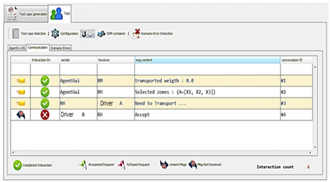
This phase requires running the system with test case inputs and comparing the obtained results with the expected ones. The purpose is to determine if there are any interactions or scenario errors. For instance, Figure 9 shows a case where no errors are detected which means that we have conformity between the obtained results and the expected results. However, Figure 10 shows the existence of an error in interaction 5 which means that there is no conformity between the results obtained and the expected results. Although interactions 2, 15, and 17 of the tested scenarios (scenario 2) run in parallel, exclusively, and inclusively with interactions 1, 16, and 18 respectively, these latter were not performed. This is guaranteed by the introduction of plugs that minimized the interval of test case inputs. Indeed, when running agents of the system under test with these inputs (whose interval is minimized), agents find themselves forced to perform only the desired interactions. In this way, it will be possible to ensure that each detected error in a given scenario is not associated with another scenario running simultaneously or in parallel.
Figure 9. End of test with no error
Figure 10. End of test with the detection of an error
5.4 Discussion and limitations
By applying our testing approach to the chosen case study, we were able to show how important it is to test each interaction and behavioural scenario separately. In reality, this has made it possible for us to pinpoint the interactions and scenarios that, in the case of error detection, led to the observed error among those that were operating concurrently, making it easier to repair the problems that were found.
Through the implementation of our testing approach on the selected case study, we successfully demonstrated the critical importance of individually testing each interaction and behavioural scenario. This approach allowed us to precisely identify the specific interactions and scenarios that, when scrutinized for error detection, directly contributed to the observed errors within the system. Indeed, by isolating and examining each interaction and behavioural scenario separately, our testing methodology provided a nuanced understanding of system behaviour, enhancing the overall effectiveness of error detection and remediation efforts.
Despite its strengths, our approach cannot be applied for some systems where the execution constraints of the interactions are not available due to the complexity and indeterminism of these systems. Furthermore, our methodology is not suitable for application in open multi-agent systems, where the introduction of new interactions is possible upon the inclusion of new agents in the system [24, 25]. Specifically, the test case inputs generated through our approach, aimed at ensuring comprehensive coverage of behavioural scenarios during system testing, may lack relevance when confronted with the emergence of new interactions due to the involvement of additional agents. Additionally, the generation of test case outputs poses challenges since it relies on meta-models that articulate the behaviour expected from new agents joining the system.
MAS testing continues to be understudied despite the rapid developments of MAS. Despite the fact that there have been only a few proposals in the literature addressing the testing of MAS, these proposals have made a considerable impact in this area. Nonetheless, they have not taken into account the particulars of the interactions between the agents that can be carried out solely, inclusively, or in parallel. In this paper, we have presented a new model-based testing approach for testing agent interactions in a multi-agent system. The suggested approach considers the distinctive properties of interactions between agents that can operate inclusively, exclusively, or in parallel. In reality, the approach is able to generate a set of test cases that cover each interaction and each scenario separately, indicating that any errors discovered in one interaction or scenario are independent of any errors discovered in other scenarios that are run simultaneously with it. For this, the AUML sequences diagram is utilised as a model, and the OCL constraints are employed to introduce the appropriate plugs. The proposed approach, supported by the tool that we have developed, has been validated in a concrete case study: PDS « Planning and Distribution System». Based on the obtained results, it would be interesting to incorporate our tool into agent development platforms as a separate library, to facilitate the process of testing interactions between the agents. In the short and medium term, we plan to adapt our approach to the complexities of open multi-agent systems. This strategic evolution involves extending the applicability of our testing methodology to scenarios where new agents can dynamically join the system, introducing additional complexity. Our goal is to fortify the versatility of our approach, making it adaptable to the evolving landscape of multi-agent systems and ensuring its continued relevance in addressing the challenges posed by open and dynamic environments.
[1] Kamdar, R., Paliwal, P., Kumar, Y. (2018). A state of art review on various aspects of multi-agent system. Journal of Circuits, Systems and Computers, 27(11): 1830006. https://doi.org/10.1142/S0218126618300064
[2] Zhang, Z., Thangarajah, J., Padgham, L. (2008). Automated unit testing intelligent agents in PDT. In Proceedings of the 7th International Conference on Autonomous Agents and Multi Agent Systems, Estoril, Portugal, pp. 1673-1674. https://doi.org/10.1145/1402744.1402759
[3] Núñez, M., Rodríguez, I., Rubio, F. (2005). Specification and testing of autonomous agents in e‐commerce systems. Software Testing, Verification and Reliability, 15(4): 211-233. https://doi.org/10.1002/stvr.323
[4] Padgham, L., Zhang, Z., Thangarajah, J., Miller, T. (2013). Model-based test oracle generation for automated unit testing of agent systems. IEEE Transactions on Software Engineering, 39(9): 1230-1244. https://doi.org/10.1109/TSE.2013.10
[5] Duff, S., Thangarajah, J., Harland, J. (2014). Maintenance goals in intelligent agents. Computational Intelligence, 30(1): 71-114. https://doi.org/10.1111/coin.12000
[6] Thangarajah, J., Harland, J., Morley, D., Yorke-Smith, N. (2014). Towards quantifying the completeness of BDI goals. In Proceedings of the 13th International Joint Conference on Autonomous Agents and Multiagent Systems (AAMAS), Paris, France, pp. 1369-1370.
[7] Coelho, R., Kulesza, U., von Staa, A., Lucena, C. (2006). Unit testing in multi-agent systems using mock agents and aspects. In Proceedings of the 2006 International Workshop on Software Engineering for Large-Scale Multi-Agent Systems, Shanghai, China, pp. 83-90. https://doi.org/10.1145/1138063.1138079
[8] Lam, D.N., Barber, K.S. (2004). Debugging agent behavior in an implemented agent system. In International Workshop on Programming Multi-Agent Systems, New York, NY, USA, pp. 104-125. https://doi.org/10.1007/978-3-540-32260-3_6
[9] Nguyen, C.D., Perini, A., Tonella, P. (2008). Ontology-based test generation for multiagent systems. In Proceedings of the 7th International Joint Conference on Autonomous Agents and Multiagent Systems, Estoril, Portugal, pp. 1315-1320.
[10] Nguyen, C.D., Perini, A., Bernon, C., Pavón, J., Thangarajah, J. (2009). Testing in multi-agent systems. In Proceedings of the International Workshop on Agent-Oriented Software Engineering, Budapest, Hungary, pp. 180-190. https://doi.org/10.1007/978-3-642-19208-1_13
[11] Abushark, Y., Thangarajah, J., Miller, T., Harland, J., Winikoff, M. (2015). Early detection of design faults relative to requirement specifications in agent-based models. In Proceedings of the 14th International Conference on Autonomous Agents and Multiagent Systems, Istanbul, Turkey, pp. 1073-1079.
[12] Winikoff, M. (2017). BDI agent testability revisited. Autonomous Agents and Multi-Agent Systems, 31: 1094-1132. https://doi.org/10.1007/s10458-016-9356-2
[13] Nguyen, C.D., Miles, S., Perini, A., Tonella, P., Harman, M., Luck, M. (2012). Evolutionary testing of autonomous software agents. Autonomous Agents and Multi-Agent Systems, 25: 260-283. https://doi.org/10.1007/s10458-011-9175-4
[14] Nguyen, C.D., Perini, A., Tonella, P. (2010). Goal-oriented testing for MASs. International Journal of Agent-Oriented Software Engineering, 4(1): 79-109. https://doi.org/10.1504/IJAOSE.2010.02981
[15] Barnier, C., Mercier, A., Jamont, J.P. (2017). Toward an embedded multi-agent system methodology and positioning on testing. In 2017 IEEE International Symposium on Software Reliability Engineering Workshops (ISSREW), Toulouse, France, pp. 239-244. https://doi.org/10.1109/ISSREW.2017.57
[16] El‐Far, I.K., Whittaker, J.A. (2002). Model‐based software testing. Encyclopedia of Software Engineering. https://doi.org/10.1002/0471028959.sof207
[17] Guassmi, D., Dehimi, N.E.H., Derdour, M. (2023). A state of art review on testing open multi-agent systems. In Novel & Intelligent Digital Systems Conferences, Athens, Greece, pp. 262-266. https://doi.org/10.1007/978-3-031-44097-7_28
[18] El Houda Dehimi, N. (2014). Towards a novel testing approach for holonic agents. In Proceedings of the 18th International Conference on Evaluation and Assessment in Software Engineering, London, UK, pp. 59. https://doi.org/10.1145/2601248.2613079
[19] Dehimi, N.E.H., Mokhati, F., Badri, M. (2015). Testing HMAS-based applications: An ASPECS-based approach. Engineering Applications of Artificial Intelligence, 46: 232-257. https://doi.org/10.1016/j.engappai.2015.09.013
[20] Gonçalves, E.M.N., Machado, R.A., Rodrigues, B.C., Adamatti, D. (2022). Cpn4m: Testing multi-agent systems under organizational model Moise+ using colored petri nets. Applied Sciences, 12(12): 5857. https://doi.org/10.3390/app12125857
[21] Dehimi, N.E.H., Benkhalef, A.H., Tolba, Z. (2022). A novel mutation analysis-based approach for testing parallel behavioural scenarios in multi-agent systems. Electronics, 11(22): 3642. https://doi.org/10.3390/electronics11223642
[22] El Houda, D.N., Soufiene, B., Djaber, G. (2022, October). Towards a new dynamic model-based testing approach for multi-agent systems. In 2022 4th International Conference on Pattern Analysis and Intelligent Systems (PAIS), Oum El Bouaghi, Algeria, pp. 1-6. https://doi.org/10.1109/PAIS56586.2022.9946659
[23] Apfelbaum, L., Doyle, J. (1997). Model based testing. In Software Quality Week Conference, pp. 296-300.
[24] Boukeloul, S., Dehimi, N.E.H., Derdour, M. (2023). A state-of-the-art review of the mutation analysis technique for testing multi-agent systems. In Novel & Intelligent Digital Systems Conferences, Athens, Greece, pp. 230-235. https://doi.org/10.1007/978-3-031-44146-2_23
[25] Hendrickx, J.M., Martin, S. (2016). Open multi-agent systems: Gossiping with deterministic arrivals and departures. In 2016 54th Annual Allerton Conference on Communication, Control, and Computing (Allerton), Monticello, IL, USA, pp. 1094-1101. https://doi.org/10.1109/ALLERTON.2016.7852357