Sunardi* | Anton Yudhana | Siswaya | Arsyad Cahya Subrata
© 2022 IIETA. This article is published by IIETA and is licensed under the CC BY 4.0 license (http://creativecommons.org/licenses/by/4.0/).
OPEN ACCESS
The current traffic light system uses a lot of fixed time signals. Fixed time signals cause traffic jams in one or several lanes due to traffic congestion. On the other hand, emergency vehicles cannot get their rights to the maximum due to the density of these vehicles. This study aims to build an intelligent traffic light with a vehicle density sensor device and a smartphone application to increase the accuracy of light timing and parse traffic density. Furthermore, in an emergency, they can still overcome and accelerate the speed of passing vehicles by manually intervening with the traffic light through a smartphone application connected wirelessly to the traffic light. The intelligent traffic light is made with Arduino Bluetooth Control (ABC), Bluetooth HC-05, Arduino Mega 2560, and infrared (IR) sensor E18-D80NK. The results show that the green light setting is based on the input from the IR sensor both near sensor (NS) and far sensor (FS) work well. When NS detects a vehicle with a green light, it increases Y seconds from the default X seconds. If FS detects a vehicle with a green light, it increases by Z seconds. Settings with the ABC application can randomly turn on the green light in four lanes according to the will of the smartphone operator.
intelligent traffic light, priority intervention, IR sensor, Arduino Bluetooth Control (ABC), Arduino Mega 2560
In recent decades, urbanization has shown a significant increasing trend. Around the world, urbanization aims to create and enhance urban areas [1]. The trend of rapid urbanization is more specifically shown in developed and developing countries. This case cannot be separated from industry development, especially manufactured goods [2], which become the economic magnet. Over time, a higher standard of living and higher economic income in urban areas has led to an increasing migration trend from rural to urban areas. Furthermore, greater diversity and quality of work, supported by superior infrastructure and services in urban areas, lead to substantial economic and social growth [3]. The United Nations projects that two-thirds of the world's population, or 7 billion people, will live in urban areas [4]. This significant development causes an increase in vehicular traffic and has excellent potential and has even been noted to increase congestion, environmental pollution, and accidents [5].
Recently, advanced technology such as smart cities has become an interesting topic to be developed. The concept that was carried out from 2009-to 2010 offers a more intelligent life by adopting an automated service system [6-8]. Due to massive urbanization, urban life is increasingly challenging with limited resources and services [9]. The smart city emerged as a solution in a new dimension of urbanization with various digital information service solutions in transportation, energy, health care, health, and other aspects closely related to human life [10]. Smart cities do not grow instantly. The development of digital culture supports the acceptance of technology. It is the main trigger for creating the smart city concept [11]. Concerning traffic density due to urbanization, smart cities, including intelligent transportation systems, allow for a solution to break down congestion, thereby minimizing the possibility of accidents and environmental pollution [12]. This is a positive response to the World Health Organization cases, which states that between 20 to 50 million people suffer from non-fatal injuries and about 1.35 million people die from traffic accidents.
Smart transport systems play an essential role and have become one of the main pillars of the smart city concept. Various studies have been developed related to this smart transport system. Special tourist services are developed in a traveler information system [13-15]. This system includes information about dynamic signage and in-vehicle notifications to provide real-time information. The information and incentives that emerge from the developed system increase compliance. A system was developed to improve transport information to the public with location tracking and e-ticketing [16-18]. The system developed has succeeded in increasing convenience and providing real-time information to commuters directly. In addition, the data is also used to study the behavior of commuters to improve services. A safety system for drivers was developed using driver assistance systems [19]. This system allows the vehicle to analyze the surrounding environment using sensors. Furthermore, the system assists several vehicle operations, such as adaptive cruise control, lighting, recognition of driver fatigue and traffic signs, collision warning, emergency braking, in-car navigation systems, and parking assistance. Another technology in the form of a fleet management system can provide automatic route planning and status updates based on location [20, 21]. This system can optimize driver management, planning, and routing to increase efficiency. The cooperative communication system was developed by utilizing wireless technology [22-24]. This system can transmit data to and from vehicles, infrastructure, and pedestrians. Automatic traffic management systems utilize road-mounted surveillance devices and other sensors to collect real-time information. Other controls such as traffic violations and dangerous incidents can be identified for immediate reporting. The data collected is then used for planning and analysis in the future. A system based on the FOG computing paradigm was developed to consider and direct vehicle routes [25]. The system can recommend alternative routes that can reduce congestion levels.
The traffic light is a fundamental part of regulating the distribution of vehicles on the highway. The traffic light is a vital instrument to regulate the smooth flow of traffic. So that proper traffic light management can minimize traffic accidents. The traffic light regulation currently uses a fixed time signal system [26, 27]. In this traffic light setting, the system cannot determine the duration of the RED (stop) and GREEN (go) signals independently. As a result, congestion often occurs on one or several lanes while the other lanes are empty. Furthermore, officers or traffic police cannot intervene in traffic lights if they find traffic conditions requiring special handling. Special handling by the traffic police is usually carried out when there is a traffic jam, prioritized vehicles such as ambulances, fire engines, and convoys of official vehicles. Handling is done by officers going down to the middle of the intersection to temporarily stop all vehicles from the intersection, then giving way to the prioritized vehicles. The proposed studies aim to realize a smart city through a smart transportation system. These studies focus on traffic information systems and route planning. Several studies focus on vehicle control systems. However, the mass control system involving many vehicles and various special needs, such as the priority of emergency vehicles to relieve traffic jams, needs further study.
Considering the trend of urbanization and the effects of congestion that often occurs in traffic, such as suffering from air pollution and delayed emergency vehicles, this research is proposed. This paper presents the design and implementation of intelligent traffic light control that can reduce traffic jams by adjusting the length of time the traffic lights are on. The length of time the red and green lights is based on the level of traffic of passing vehicles. Furthermore, traffic control officers can adjust the traffic light manually if vehicles need to be prioritized to pass. This system facilitates traffic light control using infrared (IR) sensors to detect vehicles and automate the change of traffic light lights according to vehicle crowds or manual intervention by traffic control officers. Arduino Uno is integrated with Bluetooth and used as a microcontroller and wireless communication for manual settings. The developed system is implemented in a prototype built on a traffic light simulation board with four intersections. The contribution of this work is the development of an intelligent traffic light control system that can adjust the duration of the stop and run signals according to the crowd of vehicles. Furthermore, this system is equipped with manual control to prioritize the lanes passed by special vehicles, where the operation can be controlled wirelessly. The proposed system can effectively break down congestion in one or several paths through the simulation. The main contributions of this work are: i) design and implementation of traffic light control system; ii) new concept for “stop” and “go” signal time interval estimation, which can be intervened manually with wireless support; iii) the algorithm implemented in the Arduino IDE was developed to set the time interval for the traffic light based on the status of the IR sensor; iv) system prototype is developed to validate its effectiveness and functionality.
The structure of the paper is as follows: Section 2 describes related works conducted by previous studies, Section 3 introduces the traffic light system, which reviews previous research related to intelligent traffic lights. Section 4 presents the design and fabrication of the developed system. Section 5 describes the operational procedures for implementing the system by testing its functionality. Finally, Section 6 reflects the most relevant conclusions and directions for further improvement.
To fulfil the facilities of the smart city concept, the smart traffic light was developed by controlling the traffic light so that it can regulate vehicle traffic automatically and effectively adapt to real-time traffic conditions. Wei et al. [28] proposed a reinforcement learning model to control traffic lights. The method is then tested with a large-scale real-life traffic data collection obtained from surveillance cameras. A framework, agent, network, and memory palace are needed in this deep reinforcement traffic light. All these needs are carried out using the Simulation of Urban Mobility (SUMO). However, the problem case used is still the simplified one intersection case. The results obtained will be different in the case of multi-intersection.
Cools et al. [29] proposed a self-organizing traffic light (SOTL) using the more Vehicle Traffic Simulator (moreVTS) platform. This method is achieved by logic: if there are one or more cars, then the traffic light will set a more extended stop signal. Nevertheless, the more cars that join the group, the less waiting time at traffic lights will be set to be. The test results obtained can reduce the average waiting time by half.
Cao et al. [30] proposed a pheromone-based traffic management framework to reduce traffic congestion. The strategy used is dynamic vehicle routing and traffic light control. In this study, road congestion is predicted by representing each vehicle as an agent that stores pheromones along the way. Next, alternative routes are established by proactive vehicle rerouting based on global distance and local pheromone. Meanwhile, the traffic light is controlled through an online strategy. The traffic light controllers developed are traffic light control not considering downstream traffic (TLC-NCDT) and traffic light control considering downstream traffic (TLC-CDT). The experiment was carried out using SUMO and is reported to have shown superior performance in overcoming road congestion.
Sajad Mousavi et al. [31] proposed a traffic signal prediction method based on a deep policy-gradient and value-function based agent. The experiment was carried out using SUMO. The traffic light control agent receives a snapshot of the current state from the simulator to be used as a control signal. The agent estimates the highest control value based on the mapping of direct observations to control signals by a policy-gradient based agent. The results obtained are reported to find a more stable control policy.
Li et al. [32] proposed a two-tier method based on a Hybrid Genetic Algorithm (HGA) to optimize traffic light management. The upper-level problem minimizes vehicle travel time, while the lower-level problem focuses on achieving network balance. To separate these two levels of problems, HGA is integrated with dynamic traffic assignment (DTA) so that they can be solved sequentially. Optimization of traffic light settings also considers dynamically changing and stable traffic patterns. The results obtained show the optimization of efficient traffic light settings.
Tajalli et al. [33] assume all vehicles are connected to develop further coordinated speed optimization and traffic light control in urban networks. These vehicles collect data on the infrastructure to find optimal signal timing and vehicle speed parameters. The experiment was developed based on the concept of Cell Transmission Model (CTM) network loading using the Vissim platform. The results obtained are reported to be able to coordinate signal timing and improve network performance due to optimized speed.
Miao and Leitner [34] developed a traffic light signal scheduling as service information applied to Connected and Automated Vehicles (CAV). Traffic light signal scheduling considers the longest and fastest waiting time. The traffic light is controlled adaptively using Adaptive Traffic Light Controller Using Static Vehicle Deadline (ATC-SD) and Adaptive Traffic Light Controller Using Dynamic Vehicle Deadline (ATC-DD). The system is implemented and verified using SUMO. The results show that the system can guarantee deadlines and outperform the default method.
Borges et al. [35] proposed traffic light control using Hierarchical Reinforcement Learning (HRL) and an Options Framework. HRL is used to establish a sub-policy to maximize vehicle flow and minimize waiting time. HRL makes it possible to combine learn abilities and make decisions. The results show that the proposed method can work better than the fixed-time traffic light model.
However, the experiments that have been described are still in a simulation framework. Furthermore, the problem used is adapted to a simple intersection. Therefore, it is necessary to carry out a more in-depth study to apply it to hardware then be applied and tested in a real environment.
Saad et al. [36] developed a traffic light control system for pedestrian crossing areas automatically using PIR sensors. The system performs sensing using a PIR motion sensor and an Arduino microcontroller to detect the presence of pedestrians and control the crosswalk traffic lights. The developed system is equipped with Bluetooth to transmit signals between traffic lights. Experiments are implemented in a real environment. The results obtained are reported to work effectively and perform tasks according to predetermined criteria. However, the PIR sensor can only reach a distance of 3m. Furthermore, a system was developed specifically to control traffic lights to assist pedestrians.
Traffic signals were initiated by John Peake Knight in 1866 in London with a police-operated semaphore [37]. This highway signaling system adopts train signals for the daytime and gas-powered red-green lights at night. In 1868, the first traffic light was installed on a fixed highway with gas-powered lights. Until finally, electric-powered traffic lights were installed in London in 1929.
3.1 Urban intersection
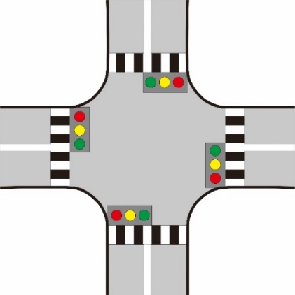
In general, traffic light operations have a specific cycle based on the type of intersection. The intersections commonly found in urban areas are intersections with three approximations (T), four approximations (Cross), and multiple approximations. In Indonesia, road driving rules apply traffic rules on the left side of the road. Generally, the traffic light operating cycle in Indonesia is clockwise. Figure 1 shows a cross-type traffic light operating cycle scheme with traffic rules on the left side of the road that are commonly applied to urban areas in Indonesia.
(a)
(b)
Figure 1. Traffic light with traffic rules on the left side of the road (a) Cross type, and (b) Clockwise cycle
3.2 Traditional traffic light
Traditional traffic light cycle control generally uses a cable network that connects each light centrally. The light control system on a traditional traffic light is straightforward because it is only based on a pre-set time. However, this static time interval cannot consider the volume of passing vehicles, so time is often wasted. The length of time the lights are not optimal also causes traffic jams, increasing pollution.
3.3 Smart traffic light
A traffic light that was developed with an intelligent system is a solution to answer various problems that occur in a traditional traffic light. One of the focuses of smart traffic light research is automatic traffic light control which was developed to regulate traffic flow by controlling vehicle speed and optimizing traffic light signals to control emergency vehicle priorities. Research related to automatic traffic light control is summarized in Table 1 to facilitate comparing the models developed based on related works in Section 2.
Several studies were conducted to obtain the optimal traffic light signal time interval. Literatures [28-35] simulated traffic light control with different platforms and methods. Meanwhile, [36] develop a prototype of a traffic light signal in pedestrian crossing areas. This paper builds a prototype to control traffic lights based on vehicle density at a highway intersection. Furthermore, officers can set traffic light signals manually to provide road signals to emergency vehicles or vehicles that have priority.
Table 1. Summary of research on automatic traffic light control
|
Models |
Definition |
|
Wei et al. [28] Simulation: SUMO |
Develop a traffic light control with a deep reinforcement learning model with actual traffic data obtained from surveillance cameras. The platform used is SUMO 2, which provides traffic light control. |
|
Cools et al. [29] Simulation: more Vehicle Traffic Simulator (moreVTS) |
Controlling traffic lights based on current traffic conditions. The platform used is more VTS 2006. |
|
Cao et al. [30] Simulation: SUMO |
Controlling the duration of a traffic light using a pheromone-based approach. The control strategies developed are traffic light control not considering downstream traffic (TLC-NCDT) and traffic light control considering downstream traffic (TLC-CDT). |
|
Sajad Mousavi et al. [31] Simulation: SUMO |
Predicting traffic light signals using deep policy-gradient algorithms and value-function-based methods using visual input data from the simulator. |
|
Li et al. [32] Simulation: Dynamic Traffic Assignment (DTA) with Hybrid Genetic Algorithm (HGA) |
Optimizing traffic light signals related to the coordination of split time, cycle time, phase sequences, and offsets simultaneously using the HGA algorithm on microscopic simulation-based DTA. |
|
Tajalli et al. [33] Simulation: Vissim |
Develop a traffic light control optimization based on the concept of Cell Transmission Model (CTM) network loading on the Vissim platform. |
|
Miao and Leitner [34] Simulation: SUMO |
Develop a traffic light signal scheduling as service information on Connected and Automated Vehicles (CAV). |
|
Borges et al. [35] Simulation: SUMO |
Controlling traffic lights using Hierarchical Reinforcement Learning (HRL) and Options Framework. |
|
Saad et al. [36] Prototipe: Arduino microcontroller and Passive Infrared (PIR) sensors |
Develop a system to regulate traffic in pedestrian crossing areas using PIR sensors automatically. |
|
Sunardi et al. (proposed) Prototipe: Arduino microcontroller, PIR sensor, and mobile device |
Develop a light traffic time interval control system based on traffic density, equipped with a manual intervention system using a mobile device to prioritize emergency vehicles. |
Based on the issue of congestion and air pollution resulting from the non-optimal time interval of the traffic light signal, this paper proposes the implementation of intelligent traffic light control to overcome these problems. Furthermore, the proposed system is equipped with an automatic controller connected to a smartphone wirelessly so that officers can operate it to provide road access to vehicles that have the right to be prioritized.
The modeling and implementation of the system are done by developing a traffic prototype using a cross intersection with left-hand traffic rules and the traffic light operating cycle in a clockwise direction. The next stage is to develop software that is applied to smartphones. The development of the prototype is done by selecting the sensor material, wireless communication, and controller used, then assembling electricity and developing algorithms using Arduino IDE. After all the devices are integrated into the prototype board and the application on the smartphone, the last stage is testing to validate the system that has been developed.
Figure 2. Intelligent traffic light model system
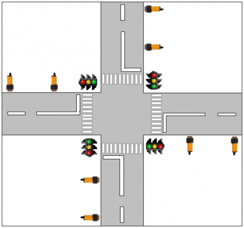
Figure 2 shows an intelligent traffic light model system using IR sensors to detect vehicles. Each lane is equipped with two IR sensors. Each of these IR sensors is defined as a near sensor (NS) and far sensor (FS) according to the sensor distance to the traffic light. The approach of the proposed intelligent traffic light control system is to detect vehicles at points close to the intersection and points far from the intersection. The proposed system aims to optimize traffic light time intervals based on traffic flow density detected using IR sensors. The time interval optimization mechanism in the proposed system is based on the pre-set RED signal timing. If the primary time RED signal has expired, the vehicle is still detected on the sensor.
4.1 Design and fabrication
The system developed consists of three central units: traffic light control devices, applications on mobile devices, and traffic light boards. The traffic light control device consists of an Arduino Mega as a microcontroller and an IR sensor. This traffic light control device is also equipped with Bluetooth as a communication protocol in the application installed on the mobile device. Furthermore, the traffic light board was built as a prototype using boards and LEDs.
4.1.1 Arduino Mega 2560
This system uses a microcontroller as the central core. The Arduino Mega 2560 board is an Arduino board that uses the ATmega 2560 microcontroller IC which was chosen as the microcontroller in this work. This board has relatively many I/O pins, 54 digital Input/Outputs, 15 of which can be used as PWM outputs, and 16 analog inputs labeled A0 to A15 as ADC. Each Analog Pin has a resolution of 10 bits and 4 UARTs. Arduino Mega 2560 is equipped with a 16 MHz crystal. The function of the Arduino Mega 2560 in this work is to receive an input signal from an infrared object detector sensor (E18-D80NK). There are eight mounted on four sides at a crossroads. There are two sensors on each side of the road: NS (sensor for a near distance) and FS (sensor for a far distance). In addition to receiving an input signal from the E18-D80NK, the Arduino Mega 2560 also receives an input signal from the HC-05 Bluetooth module, which is sent from the Arduino Bluetooth Control (ABC) application installed on the android smartphone via Bluetooth to Bluetooth HC-05. These two input signals will then be processed by the Arduino Mega 2560 to determine the length of time the green light is on in the Traffic Light Display. The programming of the algorithm that is included in the Arduino Mega 2560 is carried out using the Arduino IDE, which can be accessed openly.
4.1.2 IR sensor
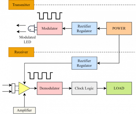
The E18-D80NK IR sensor is used in this system. The basic working concept of the object detection sensor is divided into two stages. The first stage is when it functions as a transmitter, and the second stage is when it functions as a receiver. Figure 3 shows a block diagram of the two stages.
Figure 3. Block diagram of the Infrared Object Detection Sensor Model E18-D80NK-N
In the first stage, the transmitter converts the electrical signal into light waves in the form of a light-emitting diode (LED). The infrared LED continuously emits infrared light to the object to be detected. This section is called the modulated LED. The power or power supply functions to ensure that the voltage inputted to the infrared LED is truly pure and stable DC. To support these needs, a rectifier regulator is installed. The rectifier functions to convert the AC signal into a DC signal, while the regulator is a regulation circuit or voltage regulator from a power supply so that the fluctuating effect of the input voltage does not affect the output voltage of the power supply and remains stable. This infrared object detection sensor includes a device sensitive to voltage fluctuations, so it is necessary to have an active component that can regulate this output voltage to be stable. So, this rectifier regulator is needed to limit the current and voltage to remain stable and the infrared LED can produce light at a constant brightness. The sensor sensitivity level is not disturbed. Modulation is the process of laying an information signal on a carrier signal. The carrier signal or carrier signal parameters are varied concerning another (i.e., the modulating signal in the form of an information signal). The modulation required a device called a modulator. The modulator is the process of superimposing data on the frequency of the carrier signal to the information/message signal so that it can be sent to the receiver via certain media (cable or air), usually in the form of a sine wave. The modulation of the sine wave will convert a baseband message wave into a passband waveform. So, this modulator, together with the infrared LED, functions to produce modulated light waves, which will be emitted to the object continuously.
In the second stage, the receiver converts the modulated light waves into an electrical signal in the form of a photodetector/phototransistor. Suppose an object blocks infrared light. The phototransistor converts the reflected light from the detected object (light energy) into a current and sends it to the Amplifier. This Amplifier is an IC Op-Amp (Integrated Circuit Operational Amplifier). Op-Amp is a Linear IC that functions as an electrical signal amplifier. Op-Amp consists of transistor components, diodes, resistors, and capacitors that are interconnected and integrated to enable it to produce high gain (gain) over a wide frequency range. The Op-Amp IC has two inputs (one inverting input and one non-inverting input) and has one output. The Op-Amp IC also has two pins for the power supply, namely the positive and negative pins. The electrical signal that the IC Op-Amp has amplified is then fed through the output pin to the demodulator. The demodulator has the opposite function of the modulator (demodulation), which is getting back data or reading data from the signal received from the sender. After going through the clock logic, the received signal will be given to the load as output.
The back of this IR sensor has a potentiometer (VR) to help adjust the detection distance. There is a VR tune information to adjust the distance of detection. So, the basic work of this sensor is if the object is in front of the sensor and is reached by the sensor, the sensor circuit output will be logic 0 or low, which means the sensor detects the object. Conversely, suppose the object is in a position that is not reached by the sensor. In that case, the sensor circuit output will be 1 or high, which means the sensor does not detect the object.
4.1.3 Bluetooth module
The HC-05 Bluetooth module is a TTL level serial communication converter (UART) into a form of wireless communication. Bluetooth is used for wireless communication protocols for traffic light control. This Bluetooth module can function as a master or slave. Unlike the other variants, namely the HC-06 Bluetooth module which can only function as a slave. Bluetooth modules HC-05 and HC-06 physically have the same shape. The most straightforward distinction is to look at the number of pins contained in each module. The HC-05 Bluetooth module has a six-pin connector, while the HC-06 has a four-pin connector.
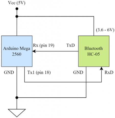
Figure 4 describes the wiring connection between the Arduino Mega 2560 and the HC-05 Bluetooth module. Bluetooth Module HC-05 is a wireless communication module via Bluetooth that operates at a frequency of 2.4 GHz with the option of two connectivity modes. Mode 1 (slave mode) acts as a data slave/receiver only, while mode 2 (master mode) acts as a master/transmitter or can also act as a transceiver (transmitter & receiver). It also has two configuration modes, namely AT Mode and Communication Mode. AT Mode is used for HC-05 module configuration settings. For example, it was changing the Bluetooth password and name. At the same time, the Communication Mode functions for wireless communication with other devices or devices or can be said to be running mode. The interfaces used to access this module are serial TxD, RxD, Vcc, and GND. There is an LED (built-in) as an indicator of Bluetooth connection to other devices such as fellow modules, android smartphones, and so on. The effective range of this module when connected is 10 m, and if it exceeds this distance, the quality of connectivity will not be optimal.
Figure 4. Configuration of Bluetooth serial communication
So, the Bluetooth Module HC-05, which is connected to the Arduino Mega 2560 microcontroller, functions to receive command signals from smartphones through the Arduino Bluetooth Control (ABC) application that is already installed in it. Using the features available in ABC, the smartphone will then send specific command signals to determine/control the lighting via Bluetooth on the Android Smartphone, which the HC-05 Bluetooth module will receive.
4.1.4 Arduino Bluetooth Control
Arduino Bluetooth Control (ABC) is an android application that allows creating Bluetooth-based projects or controlling Arduino boards via Bluetooth. Projects are created by adapting the new features available in the ABC application. The settings section allows project developers to customize the required applications through a straightforward and intuitive interface. This application will also intelligently remember the Bluetooth module the user has used and will always try to connect to the newest module automatically, so there is no need to select it every time use it. In this work, the ABC application is used to control the traffic light or determine the time when the green light is on in such a way, based on input from smartphone operators, taking into account the current traffic conditions in real-time.
4.2 System implementation
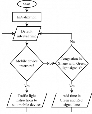
The concept of the operating cycle and manual intervention performed by the operator is shown in Figure 5. The system starts by initializing all the conditions of the sensors and LEDs. Next, the traffic light is given a default interval time to run the traffic light cycle. After the system runs with the default interval time, the system will read the condition whether there is intervention from the mobile device that is done manually by the officer or not. If there is an intervention, the traffic light will work based on the instructions given by the mobile device. If there is no intervention, the system will read the condition of the density of vehicles, especially on the path with GREEN light signals. Suppose there is traffic congestion, which is detected by the IR sensors. In that case, the system will give additional time on the path with the GREEN light signal, giving longer time on the path of the RED signals. The system will provide a default interval time if no traffic density is detected.
Figure 5. Concept of the operating cycle with lane intervention
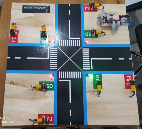
The Arduino Mega 2560 board and its supporting components, such as the HC-05 Bluetooth module and the E18-D80NK IR sensor, are assembled into a single circuit integrated into the traffic light display box. In this system, the ATmega 2560 microcontroller IC is planted with a program so that the system can work according to the original purpose of this device. The result is a prototype intelligent traffic light controlled using a smartphone, as shown in Figure 6.
Figure 6. Proposed of intelligent traffic light
Hardware testing includes testing the connectivity of the ABC application installed on the smartphone to the HC-05 Bluetooth module and testing eight infrared object detector sensors, both NS and FS. Tests were also carried out on the Arduino Mega 2560 board to receive input signals from the infrared object detector sensor (E18-D80NK), which numbered eight, and input signals from the HC-05 Bluetooth module. The last is to test whether the traffic light props can display according to the input from the ABC application & the object detector IR sensor.
5.1 ABC test
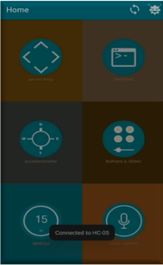
Testing is done by clicking on the ABC application software that has been installed on the smartphone and making sure Bluetooth is active. To connect to Bluetooth, the user must select the appropriate Bluetooth series. The application will successfully connect to Bluetooth and display a “Connected to HC-05” notification, as shown in Figure 7a.
The proof is also done by pressing buttons 1 to 4, as shown in Figure 7b. Button A to turn on the green light in lane 1, button B to turn on the green light in lane 2, button C to turn on the green light in lane 3, and button D to turn on the green light in lane 4. The four buttons can function to activate the green light in lane 4. four lanes of traffic either alternating/adjusting with the push of a button. At the same time, the other two buttons are used for secondary purposes. Green signal control manually through the ABC application is carried out with the following pseudo-code.
1 void serialEvent2()
2 {
3 while (Serial2.available()) {
4 char inChar = (char)Serial2.read();
5 Serial.print(inChar);
6 if (inChar == '1'){counter =0; Serial.println ("Lane 1");}
7 if (inChar == '2'){counter=20; Serial.println ("Lane 2");}
8 if (inChar == '3'){counter=40; Serial.println ("Lane 3");}
9 if (inChar == '4'){counter=60; Serial.println ("Lane 4");}
10 }
11 }
|
(a) |
(b) |
Figure 7. The display of the ABC application (a) connected to the traffic light system via Bluetooth HC-05 series, and (b) the button to manually activate the GREEN signal traffic light
5.2 IR E18-D80NK sensor test
The test in this section is carried out by alternating blocking sensors, both NS and FS. The parameter for the success of the object detector sensor test is proven by activating the Serial Monitor on the Arduino IDE. Serial Monitor will show logic 0 if the sensor is closed, and vice versa Serial Monitor will show logic 1 if the sensor is open. The results of the IR sensor test are shown in Table 2.
Table 2. IR sensor test E18-D80NK object detector
|
Lane |
Sensor |
Treatment |
Output |
||||||
|
1 |
NS |
open |
close |
open |
close |
1 |
0 |
1 |
0 |
|
FS |
open |
open |
close |
close |
1 |
1 |
0 |
0 |
|
|
2 |
NS |
open |
close |
open |
close |
1 |
0 |
1 |
0 |
|
FS |
open |
open |
close |
close |
1 |
1 |
0 |
0 |
|
|
3 |
NS |
open |
close |
open |
close |
1 |
0 |
1 |
0 |
|
FS |
open |
open |
close |
close |
1 |
1 |
0 |
0 |
|
|
4 |
NS |
open |
close |
open |
close |
1 |
0 |
1 |
0 |
|
FS |
open |
open |
close |
close |
1 |
1 |
0 |
0 |
|
After testing the IR sensor by closing the sensor area using objects, the output produced is in line with expectations. The resulting output is 100% following the treatment given for both NS and FS sensors. This test shows that the E18-D80NK IR sensor can be used as the primary sensor for detecting vehicle objects in actual implementation.
5.3 Traffic light test
This test is carried out in three stages: i) testing by default when there is no input from the ABC application and the IR sensor; ii) testing when there is input from ABC; iii) testing when there is input from the IR sensor.
Testing when by default will form a loop starting from cycle 1 to cycle eight, and after that, it returns to cycle 1. And so on with each predetermined time during programming. The measure of the success of this first stage of testing is the cycle of changing the green light in a clockwise direction. There is a sequence of alternating lights starting from lane 1 to lane 4.
The second stage of testing is when there is an input / given input from ABC through the buttons, namely buttons one, two, three, or four, as follows: i) when the A button is pressed, lane one green lights up, and lanes two, three, and four all turn red; ii) when the D button is pressed, lane four green lights up, and lanes one, two, and three all turn red; iii) when the B button is pressed, lane two green lights up, and lanes one, three, and four all turn red; iv) when the C button is pressed, lane three green lights up, and lanes one, two, and four all turn red.
The measure of the test's success in this second stage is when the user as a controller, for example, a traffic police officer, presses a button either randomly or sequentially. The GREEN light on the props lights up according to the button pressed. The third testing stage is when there is input from the IR sensor. As previously explained, two sensors are used in each lane, namely NS and FS. So, for the four lanes, there are eight sensors in all. According to the program design that is made for NS, if it detects a vehicle, the green light, which defaults to lit for X seconds, will be added for Y seconds so that the light turns on for XY seconds. Likewise, for FS, if it detects a vehicle, the green light that defaults to lit for X seconds will be added for Z seconds to turn the light to XZ seconds. The success parameter of this third stage is the addition of the green light time according to the sensor that detects the vehicle. Based on the three stages of testing carried out, it can be concluded that the traffic light props can display according to the input given, either by default, coming from the ABC application or input from the IR sensor.
Intelligent traffic light control has been developed to provide manual intervention based on the lane when an emergency vehicle is passing. The system is built with the Arduino Mega 2560 microcontroller programmed through the Arduino IDE. Through this software, Arduino is programmed to perform functions embedded through programming syntax, and an ABC application is installed on a smartphone to control the intelligent traffic light system via Bluetooth. The results showed that the green light setting, which rotates clockwise with each green light on each lane for X seconds, can work well. The input from the infrared object detection sensor, both NS and FS, can be responded to well by the program created/uploaded to the Atmega 2560 microcontroller chip. When the NS detects a vehicle, the green light will increase Y seconds from the default X seconds. Likewise, if the FS detects a vehicle, the green light will increase by Z seconds from the default X seconds. Likewise, the ABC application software settings can randomly turn on the green light in the four existing lanes, according to the wishes of the smartphone operator. So, both the eight infrared object detection sensors and the ABC application software can function to regulate traffic flow at crossroads or the existing four-lane roads adjust to the density of passing vehicles. The limitation of this research is that it is still a prototype. The future research that will be carried out is to implement it in real areas. Testing the IR sensor for temperature changes also needs to be tested in-depth.
This work was supported by Universitas Ahmad Dahlan (Grant No.: R/124/B.6/III/2022).
[1] Szabo, C.P. (2018). Urbanization and mental health: A developing world perspective. Current Opinion in Psychiatry, 31(3): 256-257. https://doi.org/10.1097/YCO.0000000000000414
[2] Gollin, D., Jedwab, R., Vollrath, D. (2016). Urbanization with and without industrialization. Journal of Economic Growth, 21(1): 35-70. https://doi.org/10.1007/s10887-015-9121-4
[3] Rodriguez-Hernandez, M.A., Gomez-Sacristan, A., Gomez-Cuadrado, D. (2019). SimulCity: Planning communications in smart cities. IEEE Access, 7: 46870-46884. https://doi.org/10.1109/ACCESS.2019.2909322
[4] Ritchie, H., Roser, M. (2018). Urbanization. Our World in Data.
[5] Qi, L., Zhou, M., Luan, W. (2015). Emergency traffic-light control system design for intersections subject to accidents. IEEE Transactions on Intelligent Transportation Systems, 17(1): 170-183. https://doi.org/10.1109/TITS.2015.2466073
[6] Lv, Z., Chen, D., Li, J. (2021). Novel system design and implementation for the smart city vertical market. IEEE Communications Magazine, 59(4): 126-131. https://doi.org/10.1109/MCOM.001.2000945
[7] Han, M.J.N., Kim, M.J. (2021). A critical review of the smart city in relation to citizen adoption towards sustainable smart living. Habitat International, 108: 102312. https://doi.org/10.1016/j.habitatint.2021.102312
[8] Araral, E. (2020). Why do cities adopt smart technologies? Contingency theory and evidence from the United States. Cities, 106: 102873. https://doi.org/10.1016/j.cities.2020.102873
[9] Kirimtat, A., Krejcar, O., Kertesz, A., Tasgetiren, M. F. (2020). Future trends and current state of smart city concepts: A survey. IEEE Access, 8: 86448-86467. https://doi.org/10.1109/ACCESS.2020.2992441
[10] Sivrikaya, F., Ben-Sassi, N., Dang, X.T., Görür, O.C., Kuster, C. (2019). Internet of smart city objects: A distributed framework for service discovery and composition. IEEE Access, 7: 14434-14454. https://doi.org/10.1109/ACCESS.2019.2893340
[11] Kashef, M., Visvizi, A., Troisi, O. (2021). Smart city as a smart service system: Human-computer interaction and smart city surveillance systems. Computers in Human Behavior, 124: 106923. https://doi.org/10.1016/j.chb.2021.106923
[12] de Oliveira, L.F.P., Manera, L.T., Da Luz, P.D.G. (2020). Development of a smart traffic light control system with real-time monitoring. IEEE Internet of Things Journal, 8(5): 3384-3393. https://doi.org/10.1109/JIOT.2020.3022392
[13] Moreno, A., Salaberria, I., López-de-Ipiña, D. (2015). New approaches in user services development for multimodal trip planning. Intelligent Transport Systems: Technologies and Applications, (313). https://doi.org/10.1002/9781118894774.ch16
[14] Bauer, J., Bedsole, L., Snyder, K., Neuner, M., Smith, M.C. (2018). Expanding traveler choices through the use of incentives: A compendium of examples (No. FHWA-HOP-18-071). United States. Federal Highway Administration.
[15] Paz, A., Peeta, S. (2009). Paradigms to deploy a behavior-consistent approach for information-based real-time traffic routing. Networks and Spatial Economics, 9(2): 217-241. https://doi.org/10.1007/s11067-008-9077-4
[16] Mauri, A., Khemmar, R., Decoux, B., et al. (2020). Deep learning for real-time 3D multi-object detection, localisation, and tracking: Application to smart mobility. Sensors, 20(2): 532. https://doi.org/10.3390/s20020532
[17] Evans, G., Guo, A.W., Blythe, P., Burden, M. (2015). Integrated smartcard solutions: Do people want one card for all their services? Transportation Planning and Technology, 38(5): 534-551. https://doi.org/10.1080/03081060.2015.1039233
[18] Caulfield, B., O'Mahony, M. (2007). An examination of the public transport information requirements of users. IEEE Transactions on Intelligent Transportation Systems, 8(1): 21-30. https://doi.org/10.1109/TITS.2006.888620
[19] Pérez, J., Gonzalez, D., Milanés, V. (2015). Vehicle control in ADAS applications. Intelligent Transport Systems: Technologies and Applications, Chapter 11, 206-219. https://doi.org/10.1002/9781118894774.ch11
[20] McLeod, S., Scheurer, J., Curtis, C. (2017). Urban public transport: Planning principles and emerging practice. Journal of Planning Literature, 32(3): 223-239. https://doi.org/10.1177%2F0885412217693570
[21] Hu, Y.C., Chiu, Y.J., Hsu, C.S., Chang, Y.Y. (2015). Identifying key factors for introducing GPS-based fleet management systems to the logistics industry. Mathematical Problems in Engineering, 2015: 413203. https://doi.org/10.1155/2015/413203
[22] Knorr, F., Baselt, D., Schreckenberg, M., Mauve, M. (2012). Reducing traffic jams via VANETs. IEEE Transactions on Vehicular Technology, 61(8): 3490-3498. https://doi.org/10.1109/TVT.2012.2209690
[23] Mandžuka, S., Ivanjko, E., Vujić, M., Škorput, P., Gregurić, M. (2015). The use of cooperative its in urban traffic management. Intelligent Transport Systems: Technologies and Applications, Chapter 14, 272-288. https://doi.org/10.1002/9781118894774.ch14
[24] Eloranta, P., Sukuvaara, T. (2015). Wireless communications in vehicular environments. Intelligent Transport Systems: Technologies and Applications, Chapter 3, 37-56. https://doi.org/10.1002/9781118894774.ch3
[25] Brennand, C.A., Boukerche, A., Meneguette, R., Villas, L.A. (2017). A novel urban traffic management mechanism based on fog. In 2017 IEEE symposium on computers and communications (ISCC), Heraklion, Greece, pp. 377-382. https://doi.org/10.1109/ISCC.2017.8024559
[26] Miller, A.J. (1963). Settings for fixed-cycle traffic signals. Journal of the Operational Research Society, 14(4): 373-386. https://doi.org/10.1057/jors.1963.61
[27] Webster, F.V. (1958). Traffic signal settings (No. 39).
[28] Wei, H., Zheng, G., Yao, H., Li, Z. (2018). Intellilight: A reinforcement learning approach for intelligent traffic light control. In Proceedings of the 24th ACM SIGKDD International Conference on Knowledge Discovery & Data Mining, London United, Kingdom, pp. 2496-2505. https://doi.org/10.1145/3219819.3220096
[29] Cools, S.B., Gershenson, C., D’Hooghe, B. (2013). Self-organizing traffic lights: A realistic simulation. In Advances in Applied Self-Organizing Systems, pp. 45-55. https://doi.org/10.1007/978-1-4471-5113-5_3
[30] Cao, Z., Jiang, S., Zhang, J., Guo, H. (2016). A unified framework for vehicle rerouting and traffic light control to reduce traffic congestion. IEEE Transactions on Intelligent Transportation Systems, 18(7): 1958-1973. https://doi.org/10.1109/TITS.2016.2613997
[31] Sajad Mousavi, S., Schukat, M., Howley, E. (2017). Traffic Light Control Using Deep Policy-Gradient and Value-Function Based Reinforcement Learning. arXiv e-prints, arXiv-1704.
[32] Li, Z., Shahidehpour, M., Bahramirad, S., Khodaei, A. (2016). Optimizing traffic signal settings in smart cities. IEEE Transactions on Smart Grid, 8(5): 2382-2393. https://doi.org/10.1109/TSG.2016.2526032
[33] Tajalli, M., Mehrabipour, M., Hajbabaie, A. (2020). Network-level coordinated speed optimization and traffic light control for connected and automated vehicles. IEEE Transactions on Intelligent Transportation Systems, 22(11): 6748-6759. https://doi.org/10.1109/TITS.2020.2994468
[34] Miao, L., Leitner, D. (2021). Adaptive traffic light control with quality-of-service provisioning for connected and automated vehicles at isolated intersections. IEEE Access, 9: 39897-39909. https://doi.org/10.1109/ACCESS.2021.3064310
[35] Borges, D.F., Leite, J.P.R., Moreira, E.M., Carpinteiro, O.A. (2021). Traffic light control using hierarchical reinforcement learning and options framework. IEEE Access, 9: 99155-99165. https://doi.org/10.1109/ACCESS.2021.3096666
[36] Saad, W.K., Hashim, Y., Jabbar, W.A. (2020). Design and implementation of portable smart wireless pedestrian crossing control system. IEEE Access, 8: 106109-106120. https://doi.org/10.1109/ACCESS.2020.3000014
[37] BBC. The man who gave us traffic lights. (2009). https://www.bbc.co.uk/nottingham/content/articles/2009/07/16/john_peake_knight_traffic_lights_feature.shtml#:~:text=.