Mohamed Esouilem* | Abdel-Hakim Bouzid | Sylvie Nadeau
© 2022 IIETA. This article is published by IIETA and is licensed under the CC BY 4.0 license (http://creativecommons.org/licenses/by/4.0/).
OPEN ACCESS
Continuity of production and employee safety are the two main concerns of today’s modern, automated, or intelligent factories. To increase safety and decrease risks in hostile working environments, manufacturers must comply with laws and regulations that are implemented in codes and standards. Unfortunately, even though companies comply with these laws and regulations and use the latest technologies, tragic accidents involving pressure vessels and piping still occur. Two such, recent events occurred in North America: in Canada, the pipeline spill of Journey Energy Inc. in 2017 and in the United States, the ExxonMobil refinery explosion in 2016. The storage of a fluid under pressure can represent a serious risk of dangerousness, not only to the employees, but also to the emergency services, the population in the vicinity and the environment. Currently, the technical aspects are the main concern of regulatory authorities (TSSA O. Reg. 220/01, RBQ B-1.1, r. 6.1, US National Board of Boiler and Pressure Vessel Inspectors (NBBI)) and the scientific community is focused on risk assessment related to structural integrity and leak tightness. The present paper surveys 50 accident cases that occurred in Canada and the United States from 1997 to 2017 related to pressure vessels and piping in petrochemical and nuclear industries. The causes of these accidents are various, but the authors focus on those related to a non-compliance with the applicable standards, namely CSA and ASME. The accidents are analyzed using a risk-ranking network and Venn diagram. Furthermore, using a case study, an in-depth analysis of an accident of a miniature boiler involving non-compliance with procedures, laws, regulations, code, and standards is conducted. The analysis of two-thirds of the documented accidents revealed that the main cause was of an organizational nature: non-compliance with standards, violation or absence of health and safety management, training deficiency, non-compliance with work procedures, and lack of clear and detailed maintenance procedures.
accident analysis, boiler, pressure vessels, risk ranking, regulation, safety, standards Venn diagram
Accidents involving Boilers, Pressure Vessels and Piping components (BPVP) still occur in Canada and United States even though regulations, codes, standards and preventive measures are well established by the concerned authorities. Indeed, manufacturers are under the obligation to follow strict regulations and standards, such as American Society of Mechanical Engineers (ASME) and Canadian Standards Association (CSA) to provide high technological equipment while the end users must comply with standards related to operations and Occupational Health and Safety (OHS). Nevertheless, accidents have occurred as recently as 2017, in Leamington, Canada and Louisiana, United States.
BPVP-related accidents often arise during operations and they are mostly the consequence of two types of failures: technical and organizational. They greatly affect industrial goods and services as well as business management, environment, and OHS. In addition, the loss of revenue and the increase of operating costs resulting from accidents are a major economic concern [1, 2]. Indeed, the explosion of BPVP have been the cause of terrible accidents in Canada (Journey Energy pipeline, Edmonton, 2017) and in the United States (ExxonMobil refinery, Baton Rouge, 2016). These accidents happened because there was a lack of risk mitigation measures that could have prevented them. The main causes and conditions at the root of these accidents are often not fully identified. Therefore, it is very difficult to prevent similar accidents on the basis of data, because they often do not reflect the actual state of things prior to the accident [3, 4].
1.1 Related work
Various studies conducted by BPVP experts state that Boilers and PVP-related accidents resulted from technical failures. According to related documentation and the analysis conducted on the different industrial sectors, two main technical risks associated with failures are identified: leakage failure and rupture failure [5]. These two risks draw attention continuously during BPVP equipment operation. It is well established that choosing PVP equipment based on their operating conditions (e.g. confined fluid, temperature, pressure etc.) can help prevent accidents [6, 7]. Kidam and Hurme [5] stated that technical failures are the most important contributors in Boiler and PVP explosions. The technical failure risks related to leakage and rupture can be monitored with a good quality control system, from the design to the operation phases, using intrinsic safety systems [8].
BPVP systems contain many instruments and devices such as pressure indicators, thermocouples, level gauges, thermo- and pressure switches and safety valves. These instruments play a major role in accident prevention and are considered as intrinsic safety systems [9]. The combination of several factors related to these safety systems, which are installed on BPVP components, can affect negatively their lifetime and can lead to devastating accidents. The absence or failure of intrinsic safety devices may lead to the operation of BPVP under conditions exceeding the limits defined by the manufacturer’s guidelines [10]. It can also lead to an unexpected malfunction of sensitive components and equipment because of weak operation control, especially in fluctuating conditions, and may result in serious accidents with severe consequences [11].
However, technical failures cannot be regarded as the only source of accidents involving BPVP systems. Technical failures should be linked in some way to the organizational failures by considering the accident sites and their environment [12]. Recently, several risk management studies revealed that organizational failures are the principal causes of accidents involving BPVP systems in most industries in North America [13, 14]. Wyckaert et al. [15] also showed that the documented accidents related to pressure vessels in Quebec, Canada are caused mostly by organizational issues. The same study also pointed to the fact that organizational failures are derived from different causes such as poor maintenance management, non-compliance with operating procedures, poor safety management and nonconformity with standards and regulations. Khobragade and Hiwase [16] came to the conclusion that the non-compliance with material composition and design specifications is the main reason of failure of PVP equipment. Therefore, the main contributing factors leading to accidents can originate from either technical or organizational sources and are often interconnected.
Furthermore, BPVP generally operate in sophisticated and complex systems under severe conditions. Industries that use these systems are usually considered as a High Reliability Organization (HRO) and include sectors such as petrochemical, nuclear, and aerospace. Several studies on industries that use advanced technologies show that accidents are strictly related to organizational aspects such as working conditions, company safety commitments and a cost-saving framework [17]. Given the close ties between the organizational and technical aspects, these systems fall under the category of complex sociotechnical systems, whose accidents analysis must be systemic. Deepwater-2010 in the United States and Lac-Megantic-2013 in Canada are recent examples of accidents in complex systems that led to human life and material losses. Complex system accidents are explained through the interconnections of their elements and organizational constraints [18]. Accidents in complex systems develop over a period of time and can be the result of technical, human and organizational failures [13]. Understanding the actual causes of accidents involving BPVP in complex industrial plants is an essential step to improving the level of safety, mitigating risk and developing appropriate strategies to prevent similar accidents.
1.2 Research objective
This work aims to investigate and analyze accidents related to Boilers, Pressure Vessels and Piping systems, by performing qualitative analyses to identify primary failure types and their causes. The analyses are applied to a set of accidents that occurred in Canada and the United States between 1997 and 2017. Furthermore, the relevance of quality control and standard compliance of all phases, i.e., design, manufacture, operations, and maintenance of BPVP will be scrutinized. The explosion of a steam generator manufactured in Quebec is used as a case study. The accident occurred despite all the efforts of Quebec authorities to reinforce laws and regulations regarding pressure installations, Building Act (B-1.1 r. 6.1) [9], the design and manufacturing code of CSA B51 [19] and the ASME boiler, pressure vessel and pressure piping code [20]. It illustrates a typical case of non-compliance with standards, codes and regulations and analyzes the non-conformities as mentioned by Bouzid [21].
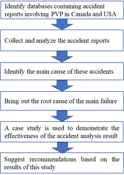
The methodological approach shown in Figure 1 is used to analyze the accidents involving boilers, pressure vessels and piping that occurred in Canada and the United States during the period of 1997 to 2017. The reason for choosing Canada and the United States is that they use the same standards and codes and have similar regulations. The methodology used is divided into five main steps:
2.1 Analysis of PVP accidents using databases
Data were collected from some 50 industrial accidents found in published reports written by Canadian and American government institutions. For the Canadian reports, the data were collected from La Commission des Normes, de l'Équité, de la Santé et de la Sécurité du Travail (CNESST) and from the Transportation Safety Board of Canada (TSB). U.S. data were gathered from the Occupational Safety and Health Administration (OSHA) and from the U.S. Chemical Safety and Hazard Investigation Board (US.CSB). The sources were open access, that is, one only needs to select the related keywords and the period of interest to upload the available data. In the present study, the keywords were boilers, pressure vessels and piping and the period was from 1997 to 2017. This 20-year period was selected to have a significant number of accidents and thus, have relevant representativity.
Figure 1. Flowchart of the methodology
In this study, only data from final investigation reports were treated, not data from primary investigation reports because these only provide temporary and indefinite causes. The analyzed accidents basically included all industry sectors that use pressure vessels and piping, except the transport industry. While the transport industry does deal with hazardous materials stored under pressure, this is beyond the scope of this paper, the related investigation can be found in the study [22].
The accidents are classified according to their main causes which are indicated in the final reports of the databases. This classification leads essentially to two kinds of failures, technical and organizational. The root causes were identified for each kind of failure and together, with the interrelationship to the two kinds of failures, were used to construct a Venn diagram. Furthermore, the descriptive statistics helped to identify the most declared type of failure as well as the most common root causes for each type of failure. Emphasis was placed on the technical and organizational failures through a case study.
2.2 Case study
The case study used hereafter was selected from the database of the fifty accidents considered in this paper. The accident involves a steam-generator, which is considered as a miniature boiler based on the ASME-BPVC (Boiler and Pressure Vessel Code), section I part PMB (Power Miniature Boilers) and it occurred in Quebec, Canada. Figure 2 summarizes the regulations, codes and standards that govern the different classes of boilers and pressure vessels including that of the case study under investigation.
Figure 2. Applicable standards and regulations of boilers in North America
The accident is investigated through detailed analytical and numerical verifications and experimental testing. The mechanical engineering calculation details including thermal and stress analyses will not be given here as they can be found in the study [23]. However, more attention was placed on the experimental tests as they can be used to support the analytical findings and help analyze the conformity of PVP regulations, code and standards applied in Quebec.
2.2.1 Boiler and PVP act and regulation
In Quebec, manufacturers of Pressure Vessels are obliged to comply with the L.R.Q. Act. chapter A-20.01, r. 1: Quebec Acts and Regulations, Act respecting pressure vessels [9]. Based on these regulations, the current boiler under investigation is considered as a pressure vessel and should comply to the rules of section 4 of division 3, which states that “The design, manufacture, testing, inspection and registration of pressure vessels, with the exception of refrigeration systems and pressure vessels destined for use in the nuclear energy sector shall conform to the Boiler, Pressure Vessel, and Pressure Piping Code (CSA B51-M1991)” [21]. With respect to the BPVP code, the term "Pressure Vessel" refers to one of the following equipment: firstly, a boiler or a furnace operated with different liquids or gases under different temperature conditions such as steam, hot liquid and hot gas; and secondly, a vessel, boiler or container containing a gas or liquid under pressure.
The regulations related to the aforementioned code are clearly defined in the scope of PVP specifications. In section 2, paragraph (1) of chapter A-20.01, r. 1: it is mentioned that the "steam, hot water or thermal fluid low-pressure boilers whose wet heating surface is less than 2.8 m2 or whose power does not exceed 30 kW " are exempted from the application of any legislation and regulations. Paragraph (1.1) excludes "open-circuit boilers not mentioned in paragraph 1 whose pressure cannot exceed 103 kPa and which have no valve between the boiler and the vent leading directly to the atmosphere". These regulation clauses may be open to interpretation regarding the application of the code in the case study. However, with reference to the definition of the term "low pressure" sometimes referred to in PVP regulations, the following cases are not regulated by the Pressure Vessels Act of Quebec: “pressure vessels other than those mentioned in subsection 3 not provided with a direct power source, containing vapour or a gas whose pressure cannot exceed 103 kPa or a liquid whose vapour pressure cannot exceed 205 kPa in absolute pressure at the maximum operating temperature. This exception does not apply to refrigerating systems”.
According to the manufacturer’s specifications, the boiler used under investigation operates at a pressure of approximately 25 psi (172 kPa), and the safety valve opens at a pressure of 60 psi (413 kPa). Given these two operating conditions, section 2 cannot, in any case, apply to the steam generator. As for point 2, the pressure and temperature indicated imply a steam-free system. Indeed, with a pressure of 172 kPa, a temperature well above 115º Celsius is required to produce water vapor. The studied steam generator creates pressure when the water is heated. The thermodynamic steam table indicates that for steam produced at a pressure of 25 psi, a water temperature of 115º Celsius must be reached, while at 60 psi, the water must reach 145º Celsius. Operating conditions of 25 psi and more than 115º Celsius does not classify the boiler under section 2. This point applies to a gas-free system such as pressurized water lines and does not apply to steam generators. In addition, the design of the steam boiler requires that the safety pressure design must be the same as the internal pressure reached when the safety valve opens.
B51-F03 of the Canadian Standard Association enacts strict administrative procedures to register the equipment plans in its clause 4.1.1. The design plan registration does not relieve the manufacturer of his responsibilities regarding the design of boilers or pressure vessels according to clause 4.1.6. The same standard requires the registration of all accessories connected to the pressure vessels in accordance with clauses 4.2.1 to 4.2.8. These clauses require that the accessories such as safety valves and pressure switches be approved and registered by the CSA or a mandated organization. Regarding the quality control systems, CSA B51-F03 requires in its clauses 5.3.1 to 5.4.2 that the boiler manufacturer demonstrate that it has a minimum quality control system based on CSA standards. Compliance with these standards could be controlled by several procedures, such as a certified manufacturer's quality control management or an accredited organism.
The ASME Boiler and Pressure Vessel Code (BPVC) provides the design rules and calculations of pressure vessels and their manufacturing, inspection and repair requirements. It is an international code accepted and adopted by most countries around the world, including Canada. The ASME code has two Sections (I and IV) that deal with boiler designs. Section IV entitled "Rules for Construction of Heating Boilers" deals with heating boilers operating at pressures less than 15 psi and more that 15 psi [24]. For the latter range (more than 15 psi), such a case is treated in Article HG-101.2, which in turn refers to section I "Power Boilers".
Section I contains several parts, namely Part PG (General Requirements), Part PMB (Miniature Boilers) and Part PEB (Requirements for Electric Boilers). Furthermore, according to Part PMB of Section I, a boiler is classified as miniature if its dimensions do not exceed 16 inches of inner diameter, 20 ft2 of heating surface, 5 ft3 of interior volume and a maximum operating pressure of 100 psi. Boilers operating at more than 15 psi must comply with the requirements of Section I of the ASME Code as specified in Article PG-2.1. Section I in ASME code can be applied to the boiler of this paper’s case study. Based on these conditions, the steam generator can be considered as a miniature boiler (Part PMB). Therefore, the requirements of the PMB of Section I and PG must be applied in this case.
2.2.2 Steam generator description
The miniature steam generator is used for commercial ironing and jewelry cleaning. It is mainly composed of a pressurized vessel and a heating resistance connected to a pressure control system, a thermostat and several valves and measuring instruments.
Figure 3. Steam generator under investigation
Figure 3 shows an overview of the steam generator. The boiler is a rectangular vessel measuring 12 x 12 x 6 in. To manufacture it, first, a molding process produces two parts made of ANSI 356F aluminum alloy, which is equivalent to UNS A03560 based on the SB-26 specification, section II part B of the ASME code. The two parts are then welded together, and the molded boiler is polished and drilled to install necessary control and operating devices, such as electrical resistance, electrical switch, pressure gauge, level indicator, safety valve and so on.
The electrical resistance is inserted inside the boiler through a hole located at the bottom and is fixed using a screw cap. To check the water level inside the boiler, a visual level indicator is installed on the same side as the heating resistance while on the opposite side, a ¼ in drain plug is provided. The top of the boiler is equipped with a water filling plug, a safety valve (dead-weight type) to release pressurized steam at 60 psi, a pressure gauge (0-160 psi) and a steam outlet valve (or service valve). The boiler can be turned on using an electrical switch. It is protected by a pressure switch, which turns the power off if the design operating pressure limit set to 25 psi is exceeded and turns it on when the pressure drops below 15 psi.
2.2.3 Steam generator operating mode
The boiler is intended for industrial use and the generated steam is mostly used for surface treatment processes. Referring to Figure 4, steam is produced at a minimum pressure of around 20 psi by boiling water using a 2000-Watt electrical resistance, mentioned above. The pressure inside the boiler is controlled via a pressure switch that maintains the pressure between 15 and 25 psi. Indeed, the pressure switch cuts the power supply if the pressure exceeds 25 psi and restores it when the pressure drops below 15 psi. The boiler is equipped with an adjustable thermostat that opens the power supply when the wall temperature reaches a predefined condition. Water is heated above 100ºC to generate steam at atmospheric pressure. However, because of the confined space, a pressure build-up is produced. Because the boiling temperature of water depends on the pressure, additional heating is needed when the pressure increases. In fact, the temperature and pressure are increased almost proportionally within the boiler’s constant volume and as mentioned previously, the boiler is protected using a pressure switch, which ensures that the pressure remains within the operating range. In addition, the steam generator is equipped with a lever-operated valve with a hose which, once activated, allows the steam generator to be supplied under pressure.
Figure 4. Operating diagram of the steam generator
2.2.4 Experimental testing
The steam generator is a system consisting of several components some of which have a safety role and others ensure its proper functioning, operation, and control. However, each component represents an intrinsic safety prevention device. Indeed, it is very important to ensure that these components are adequate and that they can handle variations in the operating conditions. This can be verified individually by isolating and testing them in similar conditions. In our investigation, three main intrinsic safety devices were tested separately, namely the safety valve, the pressure switch and the thermostat and heating resistance.
Figure 5. Diagram of the experimental set-up to test the safety valve
A safety valve similar to the one used in the damaged-steam generator was tested experimentally. The test was conducted using the laboratory compressed air line at room temperature. The experimental setup is shown in Figure 5. It consisted of the safety valve, which was connected to the compressed air line including a pressure regulator, a control valve, a 0.1 psi precision pressure gauge and a purge valve. The compressed air line was connected to the test setup using a quick connect fitting. The control valve could be closed to isolate the setup circuit and check for leaks. The pressure at which the safety valve opened to release the overpressure was recorded to be compared to the specified value.
Before performing the test, one should be sure that there are no leaks in the pressure line. This is done by replacing the safety valve by a solid plug and pressurizing the assembly to 100 psi. The setup is then isolated by disconnecting the quick connect fitting and the reading of the pressure gauge is monitored. This test showed no leakage in the circuit. The purge valve V2 was closed when the circuit was pressurized via control valve V1. The latter was actuated manually, and the pressure was slowly increased until the safety valve opened. The pressurization rate was reduced when the threshold pressure set by the manufacturer was approached. The pressure release was then recorded and compared to the value specified by the manufacturer. The circuit was then purged using valve V2 and the test was repeated five times for repeatability checks.
The pressure switch was tested using the same circuit as the one used to test the safety valve. The safety valve was dismounted from the circuit and replaced by the pressure switch, which has an integrated relay. The experimental setup is shown in Figure 6. A voltmeter was connected to the pressure switch circuit to indicate when the relay switches were on or off. When the purge valve V2 is closed and the system is not pressurized, the voltmeter should indicate a voltage and therefore, the relay associated to the pressure switch is on, which provides current to the electrical resistance to heat water and produce steam.
The pressure from the air circuit was then slowly increased using the control valve V1 until the threshold pressure was reached, which should switch the relay off. This was detected by the voltmeter indicating that the electrical resistance was no longer powered. The purge valve V2 was then actuated to increase slowly the pressure in the circuit. This was done until the relay switches on, indicating that the electrical resistance was again powered. The pressure levels that switch the heater on and off were recorded. The test was repeated five times.
Figure 6. Diagram of the pressure switch test set-up
The adjustable thermostat and heating resistor of the exploded steam generator were then tested. Their working conditions were checked using a multimeter and a simple experimental setup, which is shown schematically in Figure 7.
Figure 7. Diagram of the test set-up of thermostat
The experimental setup consisted of a thermostat connected to a multimeter at the contact points to indicate the opening and closing of the relay.
A hot plate was used as the heat source to trigger the thermostat. The resistance supply cut-off temperature was then recorded. At room temperature and using the button on the resistance head, the thermostat was set to its cut-out position at a minimum temperature. The multimeter indicated the open position of the switch, which corresponds to the supply of current to the heating resistor. Heat was then applied gradually to the system through the hotplate. The temperature rose until the relay closed, causing a power cut to the heating resistor. The temperature reading was taken on the surface of the thermostat that is in contact with the boiler as well as inside it on the surface of the expansion plate. The test was repeated at the maximum temperature trigger position as well as at an intermediate temperature.
2.2.5 Numerical test by finite element
The numerical 3D finite element model was developed using the Ansys software. Figure 8 shows the 3D model of the aluminum boiler used in the analysis.
Figure 8. 3D model of the boiler used
The model was as accurate as possible, including shape and curvature details, to reproduce the actual behavior when applying pressure. The wall thickness of the steam generator varies. It is about a ½-inch thick on the side of the openings of the heating element and the water level indicator, whereas the other surfaces are about 3/8-inch thick. Moreover, the thickness varies by about 5 to 10%. These variations are due to poor control in the manufacturing process.
To simplify the modeling while remaining conservative in the analysis, the measured thicknesses were increased to the millimeter. The circumferential weld of the boiler was not modeled. Therefore, the results do not consider the heat affected zones and defects that are present in the weld. SOLID92 tetrahedron structural elements defined by ten nodes each with three degrees of freedom in displacement were used for the mesh. The stress analysis was performed with pressures of 25 and 60 psi applied to the boiler in 5 psi increments.
The results of the accident analysis are first presented. This analysis treats the database of the fifty accidents collected from the CNESST and TSB of Canada and OSHA and USCSB of the U.S. Equipment failures and their root causes are identified. Then their relative contributions to the total number of accidents in percentage are provided. Data obtained from experimental tests and analytical computations concerning the steam-generator used in the case study are then discussed. The non-compliance of the steam-generator with Quebec PVP regulations and the ASME BPVP code conformity adopted in Canada are then discussed.
3.1 Analysis of BPVP accidents
Examination of the final reports provided by the aforementioned authorities in the databases indicated that most of the PVP accidents originated from two kinds of failures: technical and organizational. The root causes of each and their interrelationships if any are specified. The results of this analysis are shown in the Venn diagram in Figure 9.
Figure 9. Venn diagram of facts leading to accident related to pressure vessels
Figure 10. a) Main failure leading to PVP accident, b) Accident’s main technical root causes and c) Accident’s main organizational root causes
Based on Figure 9, it is clear that rupture and leakage are the two main causes of technical failures. Their root causes are also presented in the same figure. As an example, corrosion and fatigue can lead to rupture and bad coupling and joint handling can induce leakage. However, organizational failures have various causes, the most important of which are procedure non-compliance and training issues. Risk ignorance and lack of specialized training are two factors that surface increasingly often. The diagram shows the complexity implied in defining all the root causes related to organizational failures.
Moreover, it was observed that some of the analyzed accidents involve both technical and organizational failures in more complex mechanisms and can be considered as systemic accidents. Their root causes are difficult to identify. However, in most cases when they occur, they have heavy consequences.
Since the main failures leading to accidents involving BPVP are identified, the focus can shift to the statistical distributions of their contribution to these accidents. The percentage at which the root causes are involved for each type of failure is also presented in Figure 10.
According to Figure 10a, 63% of accidents are associated to organizational failures, whereas only 37% of accidents are technically driven. As already underlined in the Venn diagram, two main causes are related to technical failures and they are distributed as follows: 56% due to rupture and 44% due to leakage as indicated in Figure 10b. As to organizational failures, the absence or lack of OHS is the main factor. Nonetheless, OHS cannot be isolated because it is present at all levels of operations. Excluding OHS, non-compliance to regulations, codes and standards is the most important factor leading to accidents, representing 24% of the cases. The non-compliance with regulations can arise during any phase of the system’s lifecycle including design and operation. It is of the upmost importance that all equipment and procedures comply with current regulations and standards. The other root causes must not be neglected. Their percentages are presented in Figure 10c.
3.2 Case study
In this section, the arguments are discussed in light of the results obtained during the experimental and theoretical tests. However, these results will be confronted with regulatory requirements to analyze the conformity of the studied Boiler. So far, it seems that organizational failures are the most important factors of accidents involving Boilers and PVP in North America. In fact, those accidents are primarily linked to non-compliance with regulations, codes and standards. The case study considered here, and selected from the treated database is a typical example showing how the non-compliance with regulations and current standards may impact the safety and security of the boiler. Indeed, the accident involving the steam generator was investigated using analytical and numerical approaches (heat transfer and thermal calculations and stress analyses) and experimental tests. The experimental setups are presented in section 2.2.4 and the analytical and numerical calculations can be found in the study [21]. The experimental results of the safety valve and pressure switch tests are presented in Table 1.
Table 1. Test results of safety valve and pressure switch
|
Number of the test |
Test of the safety valve (psi) |
Test of pressure switch (psi) |
|
|
|
Opening pressure |
Opening pressure |
Closing pressure |
|
1 |
62 |
21 |
25 |
|
2 |
61 |
21 |
25 |
|
3 |
62 |
20 |
24 |
|
4 |
62 |
21 |
25 |
|
5 |
63 |
21 |
25 |
The results obtained from the analytical and numerical finite element approaches are summarized in Table 2. The results of a spherical boiler as a better alternative to the rectangular boiler under investigation were added for comparison. The analytical approach treats the largest plate-section of the rectangular steam generator using plate theory. Stresses at the center and at the corners or the periphery of the plate using different boundary conditions are presented. The stress values are compared to the allowable stress of the steam-generator material (356F).
The operating conditions of the heating resistor were checked. The value of its resistance was compared with a new resistance. The two resistances gave 6.9 and 7.0 ohm respectively. The adjustable thermostat was tested at three trigger positions. The adjustment button enabled triggering at different temperatures. The maximum and minimum temperatures are given in Table 2. This includes the values at an intermediate position of the thermostat. The tests were duplicated to validate the results.
Table 2. Thermostat test results
|
Control button position |
Thermocouple on wall |
Thermocouple on sheet metal |
|
|
Maximum |
Test#1 |
373 |
300 |
|
Test#2 |
375 |
303 |
|
|
Middle |
Test#1 |
272 |
225 |
|
Test#2 |
281 |
233 |
|
|
Minimal |
Test#1 |
222 |
203 |
|
Test#2 |
221 |
219 |
|
The analytical and numerical methods showed that the stresses at the center were rather high under the possible operating loads. The 25 psi pressure was the normal working condition while the 60 psi pressure was the upset condition that can happen for example if there is a failure of the pressure switch. This is the maximum pressure that the boiler should support before the pressure relief valve opens.
According to the results of the FE method, the stresses obtained can be as high as 168 MPa at a design pressure of 60 psi. As stated in the ASME code, the design pressure is the pressure that allows the safety valve to open. The mentioned stresses at the junction of the boiler plates are greater than the yield stress of the boiler material of 65 MPa and even exceed the ultimate tensile stress (UTS) at room temperature, which is 131 MPa. Even if this value refers to a stress concentration, the stresses at the center of the plates remain high at 93 MPa, which indicates a plastic deformation of the steam generator.
The theory of plates with lateral pressure loading confirms these results. Indeed, the stress value obtained at the center of fixed plates is 130.5 MPa and the stress value obtained with a simply supported plate is 121.8 MPa, as shown in Table 3.
Table 3. Stresses calculated using different methods and comparison with the material’s allowable stress (356F)
|
Method of analysis |
Stress at the center (MPa) |
Stress at the periphery (MPa) |
||
|
|
Pressure (psi) |
Pressure (psi) |
||
|
|
25 |
60 |
25 |
60 |
|
Square plate |
54.3 |
130.5 |
24.5 |
58.7 |
|
Simply supported plate |
50.7 |
121.8 |
0 |
0 |
|
Finite element study |
39 |
93 |
70 |
168 |
|
Spherical boiler |
1.4 |
3.3 |
1.4 |
3.3 |
|
Yield stress |
65 |
65 |
65 |
65 |
|
UTS |
131 |
131 |
131 |
131 |
With normal operation conditions of 25 psi pressure, the numerical analysis showed that the stresses reached 70 MPa at the discontinuity zones and especially at the junctions between the mentioned plates. The obtained stress value was higher than the yield stress value of the boiler material but did not exceed the ultimate tensile stress. At the center of the plate, the theoretical results gave values of 50.7 MPa and 54.3 MPa depending on the support’s position. These stresses are higher than the allowable stress of the boiler material at room temperature, which is around 1/3 of the yield stress or 21 MPa.
The analytical, numerical and experimental studies show that the stresses in the boiler are significantly higher than the yield stress of 356 F aluminum alloy at a temperature above 250°F when the water level is low in the boiler. The experimental tests showed that the boiler overheated once most of the water had evaporated. The most probable causes of the evaporation could be a gross leak or one of the valves was open. An aluminum of lower quality than that required by the ASME BPV code was used to manufacture the boiler. In addition, the strength of the aluminum casting alloy used is considerably reduced when exposed to heat. The explosion could have been avoided if a liquid level sensor had been present and functional to detect the lack of water. In addition, a steam boiler operating under extreme conditions must be equipped with an automatic heat source cut-off system in the event of low water level.
This case study provides a comprehensive view of the main root causes of a PVP accident in North America, and highlight that codes, standards, and procedures alone cannot prevent accidents. The cause of the explosion of the steam generator was due to the unsuitability of the material for a high temperature application and the lack of proper safety instruments. Indeed, the excessive heating of the boiler led to its explosion because the resistance of the material 356 F decreases drastically as the temperature increases, in particular, above 200°F and the boiler was not equipped with safety devices to avoid failure. The results of the case study lead to the recommendations given in Table 4.
The absence of a health and safety management system is in general the main cause of accidents. The non-systematic implementation of OHS in companies in certain industries is a reality because OHS is often considered as a secondary support service [25]. Unfortunately, accident prevention is often considered as an added cost, not an added value and an option and not an obligation [26]. In fact, more than 80% of accidents have, as their main or secondary cause, non-compliance with OHS regulations. Non-compliance with procedures or even worse, their complete absence, implies a violation of OHS regulations, which can lead to administrative, disciplinary, legal or criminal prosecution in Canada’s legislation. Overflow of stored products following pipe-fitting disconnections is the most frequent cause of accidents in this category, causing fires and explosions.
Table 4. Recommendations vs. main failure
|
Recommendation |
Main failure |
|
The manufacturer of the steam generator must comply with the Act and Regulations of Quebec, B-1.1, and must design the boiler according to the CSA B-51-F03 standard and the requirements of the ASME code. |
Organizational |
|
Even if an Engineering seal and signature is not required, the steam generator should be subject to mandatory reporting of plans and specifications by the manufacturer. |
Organizational |
|
The boiler manufacturer must demonstrate that it has a quality control system recognized by a Canadian or American authority. |
Organizational |
|
Aluminum casting alloys in reference to ASME SB-26 (or ASTM B-26), including material 356 F, must not be used to manufacture boilers under any circumstances. |
Organizational |
|
The boiler was not continuously monitored by a certified operator. In fact, it must be equipped with an automatic heat source cut-off system in the event of low water level. |
Technical |
|
Considering the conditions of use of the steam generator, the nature of the manipulations of the operator and all the possible activities around it, the requirement of a suitable protector of the tubular glass of the water level indicator is recommended. |
Organizational |
|
The use of a valve at least ½ inch in diameter located at the lowest possible water level is required for the drain piping system. |
Technical |
|
The type of safety valve or relief valve should be a sealed spring at least ½ inch in diameter and not of the dead-weight type. |
Technical |
|
Avoid the manufacture of pressure boilers of rectangular shape. Spherical or cylindrical shells are better suited to withstand pressure loads and therefore, are recommended for this type of application. |
Technical |
While technical causes are not always the main reason for accidents, the consequences of maintenance subcontracting are often the root cause. In general, SMEs have a more unfavorable record of fatal accidents at work than large companies due to their limited OHS resources [27]. Their budgetary scale and lack of investment in OHS are often to blame. Poor maintenance also presents a significant risk. Effective management and maintenance planning can prevent unsafe situations in the industry. Adequate upstream coordination between maintenance and OHS services, as well as proper training, can significantly reduce the frequency of accidents. Inadequate training has an impact on other organizational causes. Indeed, lack or poor training can lead to dangerous consequences when the staff is oblivious to the seriousness of their actions. Therefore, proper training has an essential role in accident prevention.
Technical causes are divided into structural integrity and leakage failures. Ruptures are caused by cracks initiated in different components (shells, connections, pipes, joints, openings, welds) causing not just leaks and spills of the confined fluids but also fires and explosions. The main causes of these ruptures and damages are extreme operating conditions, such as high temperatures and high pressures. The consequences of pressure vessel bursts are numerous and various in nature, for example, pressure wave emissions, the sudden expansion of confined fluid, explosion, fire, and fragment projections, to name a few. Leaks represent a recurring problem in pressurized equipment. Operating accessories (pipes, valves, fittings, seals, etc.) constitute the most sensitive parts of pressure vessels. The slightest defect (improper installation, improper tightening, degraded material, etc.) can cause a leak, leading to serious consequences such as the creation of a pool of flammable or toxic products, dangerous vapors, a cloud of gas, etc. Such incidents can ultimately result in fires, explosions or even asphyxiation or the poisoning of workers [28].
In the present paper, a relatively important number of accidents involving Boilers, Pressure Vessel and Piping is analyzed. Accidents that occurred in North America during the period between 1997 and 2017 were the subject of a root cause analysis. The accidents were collected from the published reports and databases of the Commission des Normes, de l'Équité, de la Santé et de la Sécurité du Travail (CNESST) and Transportation Safety Board of Canada (TSB) for Canadian cases and the Occupational Safety and Health Administration (OSHA) and the U.S. Chemical Safety and Hazard Investigation Board (US.CSB) for American cases.
The study helped to understand and identify the main causes of accidents involving Boilers and PVP, which constitute a danger to workers, the environment and public health and safety. The study is primarily based on qualitative analyses using a Venn diagram to identify the main failures leading to those accidents and their root causes. A graphical representation of the percentages of each failure causes/effects is given. One accident was selected and treated as a case study to confirm the results of the accident analyses.
The Venn diagram in Figure 9 shows that the principal failures are essentially technical or organizational. Furthermore, rupture and leakage are the main root causes of technical failures. As for organizational failures, they are linked to various causes, mainly non-compliance with procedures and training issues including risk ignorance, lack of specialized training and low-level risk assessment. It is not straightforward to circumscribe all the root causes of organizational failures, and this may be why most researchers are concerned with technical failures. Moreover, many accidents treated in this work considered as systemic are rather complex to analyze and involve both technical and organizational failures. The root causes of these accidents are actually difficult to point out. Nevertheless, it is obvious that organizational failures are largely more prevalent than technical failures.
The experimental, numerical and analytical investigations conducted for the case study show that the steam-generator involved in the selected accident did not comply with Quebec regulations and the Canadian codes and standards. This case clearly demonstrates that the implementation of codes, standards and regulations does not always ensure that design or operation phases are in compliance. The compliance with standards should continuously be ensured and thoroughly verified.
The authors would like to acknowledge the funding of the Natural Sciences and Engineering Research Council of Canada (NSERC) as well as the support and infrastructure of École de technologie supérieure (ÉTS).
[1] Steinhauser, G., Brandl, A., Johnson, T.E. (2014). Comparison of the Chernobyl and Fukushima nuclear accidents: A review of the environmental impacts. Science of the Total Environment, 470: 800-817. https://doi.org/10.1016/j.scitotenv.2013.10.029
[2] Abdunazarov, J., Azizov, K., Shukurov, I. (2020). Method of analysis of the reasons and consequences of traffic accidents in Uzbekistan cities. International Journal of Safety and Security Engineering, 10(4): 483-490. https://doi.org/10.18280/ijsse.100407
[3] Dekker, S. (2016). Drift into Failure: From Hunting Broken Components to Understanding Complex Systems. CRC Press. https://doi.org/10.1201/9781315257396
[4] Sikora, I., Hari, B.L., Hanusch, M. (2020). Human factors approaches and models in LOC-I accident analysis and prevention: Flight crew resource management techniques as a risk mitigation tool. International Journal of Safety and Security Engineering, 10(3): 301-310. https://doi.org/10.18280/ijsse.100301
[5] Kidam, K., Hurme, M. (2013). Analysis of equipment failures as contributors to chemical process accidents. Process Safety and Environmental Protection, 91(1-2): 61-78. https://doi.org/10.1016/j.psep.2012.02.001
[6] Arunraj, N.S., Maiti, J. (2010). Risk-based maintenance policy selection using AHP and goal programming. Safety Science, 48(2): 238-247. https://doi.org/10.1016/j.ssci.2009.09.005
[7] Bouloiz, H., Tkiouat, M., Garbolino, E., Bendaha, T. (2013). Contribution to risk management in industrial maintenance. In Proceedings of 2013 International Conference on Industrial Engineering and Systems Management (IESM), pp. 1-7.
[8] Kletz, T.A. (2009). Accident reports may not tell us everything we need to know. Journal of Loss Prevention in the Process Industries, 22(6): 753-756. https://doi.org/10.1016/j.jlp.2009.08.017
[9] RBQ (2019). Loi sur les appareils sous pression. Chapitre A-20.01(2017).
[10] Hendershot, D.C. (2011). Preparing for the unexpected–A case for inherently safer design. Journal of Chemical Health & Safety, 18(5): 62-63. https://doi.org/10.1016/j.jchas.2011.07.004
[11] Lian, G., Niu, Y., Zhang, X., Lu, Y., Li, H. (2018). Analysis of causes of boiler accidents in power plant and accident handling based on mathematical statistics. In 2018 International Conference on Engineering Simulation and Intelligent Control (ESAIC), pp. 17-20. https://doi.org/10.1109/esaic.2018.00012
[12] Milch, V., Laumann, K. (2016). Interorganizational complexity and organizational accident risk: A literature review. Safety Science, 82: 9-17. https://doi.org/10.1016/j.ssci.2015.08.010
[13] Reason, J. (2016). Organizational Accidents Revisited. CRC Press. https://doi.org/10.4324/9781315543543
[14] Underwood, P., Waterson, P. (2013). Systemic accident analysis: Examining the gap between research and practice. Accident Analysis & Prevention, 55: 154-164. https://doi.org/10.1016/j.aap.2013.02.041
[15] Wyckaert, P., Nadeau, S., Bouzid, H. (2017). Analysis of risks of pressure vessels. In Gesellschaft für Arbeitswissenschaft: Soziotechnische Gestaltung des digitalen Wandels - kreativ, innovativ, sinnhaft (Zurich, Suisse, Fev. 15-17, 2017) Coll. «Kongress der Gesellschaft für Arbeitswissenschaft». vol. 63.
[16] Khobragade, R., Hiwase, V. (2017). Design, and analysis of pressure vessel with hemispherical and flat circular end. International Journal of Engineering Science and Computing, 7(5): 12458-12469.
[17] Le Coze, J.C. (2019). Vive la diversité! High reliability organisation (HRO) and resilience engineering (RE). Safety Science, 117: 469-478. https://doi.org/10.1016/j.ssci.2016.04.006
[18] Underwood, P., Waterson, P. (2014). Systems thinking, the Swiss Cheese Model and accident analysis: A comparative systemic analysis of the Grayrigg train derailment using the ATSB, AcciMap and STAMP models. Accident Analysis & Prevention, 68: 75-94. https://doi.org/10.1016/j.aap.2013.07.027
[19] Yahya, N.A., Daas, O.M., Alboum, N.O.F. (2018). Design of vertical pressure vessel using ASME codes. Proceedings of First Conference for Engineering Sciences and Technology, 2: 653-664. https://doi.org/10.21467/proceedings.4.33
[20] Pastor, T.P., Vattappilly, J. (2020). Section VIII–Division I: Rules for Construction of Pressure Vessels. Online Companion Guide to the ASME Boiler and Pressure Vessel Codes. https://doi.org/10.1115/1.861981_ch21
[21] Bouzid, A.H. (2015). Safety and reliability assessment of a miniature steam generator. In Proceedings 19th Triennial Congress of the IEA, 9: 14.
[22] Peignier, I., Leroux, M.H., de Marcellis-Warin, N., Trépanier, M. (2011). Organizational safety practices of hazardous materials carriers. Transportation Letters, 3(3): 149-159. https://doi.org/10.3328/tl.2011.03.03.149-159
[23] Bouzid, A.H. (2004). Étude de sûreté de fonctionnement d’un générateur de vapeur, in CNESST. 55.
[24] ASME., Section III. (2015). Rules for Construction of Nuclear Power Plant Components. Division I. American Society of Mechanical Engineers, New York, NY.
[25] Nenonen, S. (2010). Safety management problems encountered by industrial service providers. In 2010 IEEE International Conference on Industrial Engineering and Engineering Management, pp. 1529-1533. https://doi.org/10.1109/ieem.2010.5674160
[26] Badri, A., Nadeau, S., Gbodossou, A. (2011). Integration of OHS into risk management in an open-pit mining project in Quebec (Canada). Minerals, 1(1): 3-29. https://doi.org/10.3390/min1010003
[27] Lescure, E., Nadeau, S., Morency, F. (2015). PME et SST: Quand la résilience est un modèle d’affaires. 50ième congrès de la SELF, 23 au 25 septembre 2015, Paris, France.
[28] Hetrick, T.M., Smyth, S.A., Ogle, R.A., Ramirez, J.C. (2017). Evaluating the potential for gasoline geysering from small engine fuel tanks. ASCE-ASME J. Risk and Uncertainty in Engineering Systems, Part B: Mechanical Engineering, 4(2): 021001. https://doi.org/10.1115/1.4037866