Jeyashree Arthanareeswaran* | Bavithra Karunanidhi | Sowmiya Muruganantham | Archana Dhamodharan | Subash Kumar Chellappan Swarnamma
© 2021 IIETA. This article is published by IIETA and is licensed under the CC BY 4.0 license (http://creativecommons.org/licenses/by/4.0/).
OPEN ACCESS
In India, transport becomes a basic commodity of daily life. As transportation starts increasing, safety has become a major concern for consumers. This paper mainly aims at reducing the fatalities caused due to accidents occurring in roadways. In general, many lives could be saved if emergency service could get accurate accident location and rescue the injured people at the minimum possible time. The Internet of Things has revlontinsed the modern world in recent times. As Global Positioning System has become an integral part of any vehicle system, this effective method is utilized to monitor the location of vehicles and send accident locations to an Accidents Monitoring and Rescue Services Centre (AMRSC) using GSM. The Accelerometer located in the vehicle system gives the live status of the vehicle position while the vehicle is in motion. Whenever an accident occurs, the signal from the accelerometer is fed to the controller. The Node MCU controller is programmed to check whether the accident has occurred and given the information to the user and AMRSC as soon as possible. Now, the system will also send the accident location acquired from the GPS along with the vehicle details through the GSM network to AMRSC. After receiving the alert message from the infected user vehicle system, the rescue team will reach the accident location as soon as possible by reading the data from the server.
accelerometer, GPS, AMRSC, GSM, Internet of Things
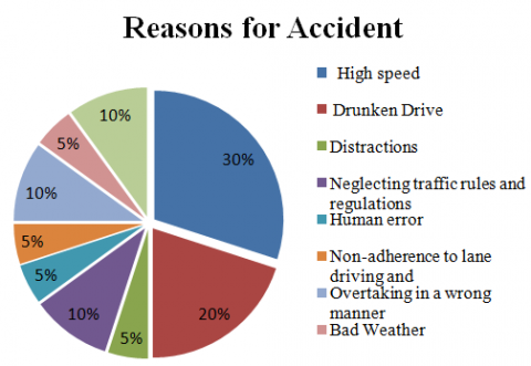
Throughout The development of transport system, though being one of the biggest revolutions of human inventions, it also brings disasters to human race by accidents. Road accidents have been the foremost cause of unexpected fatalities for decades [1]. The causes of road accident with accident rate are shown in the Figure 1.
Figure 1. Causes of road accident
The main reason for road accidents are given below such as:
Thus, there are many factors that serve as root cause for accidents, but the high speed remains the primary concern.
Even though advised and regulated by government, the control of road accidents had always been a tedious task. Despite these causes, if the accident information could reach the emergency services much faster and their response in return, lot of fatalities could have been reduced. According to the statistical approach, more than 50% fatalities are due to the time delay of the injured user to the hospital. As of now, detecting accident at the instant of occurrence and reporting the same to the emergency services is very important to save the life of a human being.
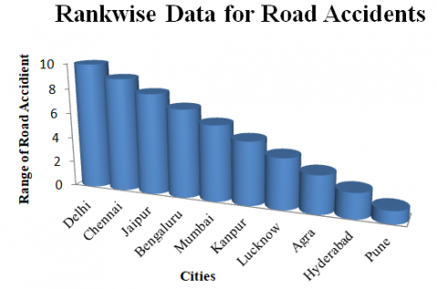
The highest accident prone zone is Delhi and the range of accident location is prescribed in the Figure 2.
As per the government data in India, nearly 1.5 lakh people got injured due to road accidents in the year 2018 with over-speeding of vehicles. The city where the accidents has occurred is shown in the Figure 2 with the top most 10 cities more prone to the accident.
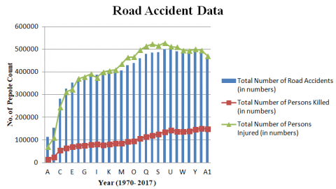
From Open Government Data (OGD) community, the database for road accident is listed. In this Figure 3 the graph clearly shows the number of road accidents observed form 1970 (A) – 2017 (A1), the number of persons injured and killed during the same years [2].
Figure 2. Cities prone in accident in India
Figure 3. Road accident data in India
From the above graph, it inferred that majority of death cases in India during the following years. The main cause for the accidents according to the survey indicates the death cases increased mainly because of the improper indication system to the hospitals and nearby ambulance. The injured people due to the accident data is around 6 lakh and the person’s death count after the accident occurred is around 1.5 lakh. The difference between accident injured and death cases are analyzed from the graph and it is necessary to the assist the accident occurred location to the hospital nearest. An efficient system is provided to the user and enabled to track the accident located region to both the family and AMRSC. As our respected ancient poets like Thiruvalluvar, Avaiyar, Bharathiyar, Bharathidasan says that “Right help at Right time” is the possible way to reduce death caused due to accidents.
Thus, here the proposed system is organised as follow. First, various accident indication methods are collected and analysed. Next, the proposed system is structured by collecting the motion data using accelerometer positioned on the car. Then, the GPS is located to track the location of the vehicle that is fitted to the system. Whenever a deviation occurred in the prescribed algorithm, controller plays a vital role. It sends message to the connected mobile number and AMRSC centre. At last, the prescribed location is observed by the AMRSC centre and immediate actions such as locating nearest hospital and giving message to the concerned hospital to rescue the injured person. This method is taken to avoid the death fatalities caused due to road accident.
In 2014, a smart phone is used based on android application for direct phone-to-phone communication employed for both accident and observing the traffic system. Here, the components used are Bluetooth, sensors and Wi-Fi used for wireless connection. The main problem in using Wi-Fi is that it consumes more power compared to Bluetooth. Here, the biggest advantage which over-weighs the disadvantage is that Wi-Fi provides a bigger range when compared to Bluetooth and this is the reason that Wi-Fi module is used to communicate with the help centre and also this information can be taken for analysis to avoid accidents, if it is frequent in a particular location and certain steps can be taken to avoid future accidents [3, 4].
In present situation, it is not possible to detect the accident occurred location and impossible to detect the accident occurred location. So, it is not to predict the accident occurred location of an individual causing death of an injured person caused due to accident. In recent days, the embedded system also uses sensors and interface components like GPS, GSM are used to track the accident occurred location and indicate the zone to the system. In addition to this, different techniques are also used to track the data and importing the data is shown with valuable results to predict crash accidents. The Bluetooth based traffic monitoring is also used to indicate the accident location by employing unsupervised analogy. There are different analysis is done in intelligent transport systems [5-9].
Thus, the vehicle accident indication system is anlaysed and a proposed system is highlighted. The research work is afoot on positioning the location of the vehicle in all environmental conditions even though, if there is no network for receiving the signals [10-17]. The major shortcomings of the above mentioned review of the existing approach are shown in the Table 1 and implies the analysis.
Considering all the disadvantages into account, the proposed system is designed to avoid the above mentioned drawbacks.
An automated system is used to analyse the accident occurring area.
Table 1. Literature survey for accident indication system
|
Methods |
Bluetooth Based Detection |
Raspberry pi Based Detection |
IoT based Intelligent System |
Ardunio Based Detection |
Machine Learning Based Approach |
Proposed Method |
|
Methodology |
Very Simple |
Difficult to Configure |
Moderate |
Very Simple |
Advanced Methodology |
Very Simple |
|
Controller |
ATMEGA 328P |
Raspberry pi |
Ardunio |
Ardunio |
Raspberry pi |
NODEMCU |
|
Sensing Element |
Ultrasonic Sensor |
Both Ultrasonic and Accelerometer |
MQ-3 sensor, Webcam, Infrared Sensor and Accelerometer |
Ultrasonic sensor |
Both Ultrasonic and Accelerometer |
Accelerometer |
|
Location Tracking |
No |
Yes |
Yes |
Yes |
Yes |
Yes |
|
Technical |
Simple to work |
Complex to work |
Simple Method |
Simple to work |
Complex to do work |
Simple Method |
|
Interface |
Easier to connect and interface |
Complex in programming and interface |
Easier to connect and interface |
Easier to connect and interface |
Complex in programming and interface |
Easier to connect and interface |
|
Accuracy |
Low |
High |
Moderate |
Low |
High |
High |
|
Size |
Small |
Moderate |
Moderate |
Small |
Moderate |
Small |
|
Time of Locating Persons |
Longer ranges may not be supported |
Highly suitable for large scale applications |
Convenient to track |
Convenient to track |
Convenient to track |
More Convenient to track Faster in ns |
|
Cost |
Moderate |
Extremely High |
Moderate |
Moderate |
Extremely High |
Comparatively Low |
|
Power Consumption |
Moderate |
Moderate |
Moderate |
Moderate |
Moderate |
Low as it is sleep mode is enabled |
|
Efficiency |
Good |
Moderate |
Good |
Good |
Better |
High |
Even though different mechanisms employed for the accident prevention and indication, the technology has not touched the peak necessity of human being (i.e. human life). The research is mainly focused on the safety and reliability of the vehicle and the human beings. Based on the review mentioned and analysis a system called AMRSC is designed. In accident indication and reporting system, the GPS is used for tracking the position of the vehicle, and GSM is used for sending the message. The NodeMCU controller is open source software embedded with the mobile number and give the signal location to the AMRSC and then GSM is used for forward the message to AMRSC and the linked family members.
The automatic accident indication and reporting system for road ways using Internet of Things system uses a MEMS ADXL335 (Micro-Electro-Mechanical-Systems) device called Accelerometer to detect sudden changes in a moving vehicle, and report such accidents with the corresponding location through a GSM network [5-9]. In addition to that, the location data is stored in the server. When the accident occurs, the accelerometer changes its co-ordinated axis. Now, the change in value is fed to the controller. The controller will check for the limit value for the proposed algorithm. When the deviation between the proposed value and the actual value then the signal is fed to the user and AMRSC centre. If there are no serious injuries, to the user, the user can respond to the message and it will not be indicated to the AMSRC Centre. Then AMRSC will neglect the message once it is ignored by the injured user. If not, the AMRSC centre will send the data to the nearest hospitals and precautions will be made to the injured person. In addition to this, the message will also be sent to the linked mobile number like mother, wife, husband etc.
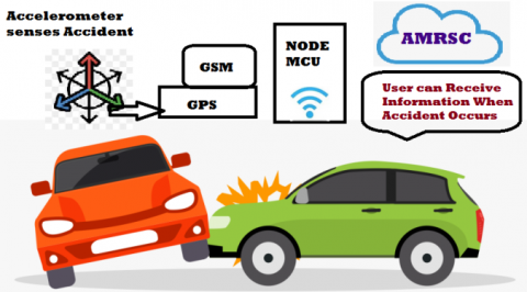
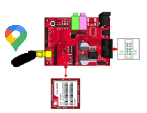
The accelerometer senses the variation of the accelerometer sensor while hitting the object. This object may include hitting tree, hitting the pavement, hitting the transformer and hitting the other vehicle etc. The pictorial representation shows the planned system model as shown in the Figure 4.
Figure 4. Overview of the proposed system
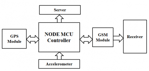
The block diagram for this accident indication and reporting system is shown in the Figure 5.
The block diagram in the Figure 5 shows the working of the proposed system. The accelerometer gives an output signal whenever an accident occurs. When the controller senses the deviation in the prescribed values, the receiver receives message related to the accident location and sent to the cloud. Thereby, further detection techniques with the implementation of Internet of Things (IoT) can be done for protection. Here, it is used to measure the dynamic accelerations (motions or vibrations) caused due to accidents and report them [18-20]. The main hardware essentials of the proposed system include:
Figure 5. Block diagram of the proposed system
3.1 MEMS Accelerometer
An accelerometer is an electromechanical device that measures acceleration due to both gravity and motions (or) vibrations. MEMS have made the accelerometer applications much more accurate with low power and minimum size. The MEMS used here act as a micro-sensors.
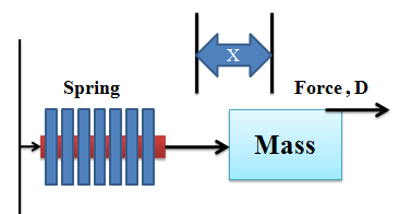
Figure 6. Spring – Mass Diagram
By Newton’s law, the working of accelerometer is mentioned as shown in the Figure 6. Generally, the force is given by
F=Mass*Acceleration =Force due to spring tension
Force due to spring tension = t * X
where, x= displacement, t = spring constant
Thus, Acceleration A= function (x).
The acceleration is calculated by finding the displacement. To measure the displacement there are different methods such as resistive method, inductive method and capacitance method. The most prominent method to measure the displacement is capacitance method.
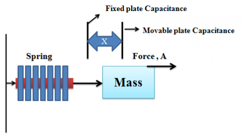
Figure 7. Displacement measurement using capacitance effect
Thus from the above Figure 7, the fixed plate capacitance is located at the initial position and movable plate is moving across the displacement (x) by applying a force (F), that activated the system to accelerate (A). Thus
A = function (X)
Capacitance = function (1/ X)
Thus, the Capacitance = function (1/A)
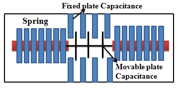
But this not possible for such a large system as it increases the component size. So, MEMS came into existence fabricated at 20 micro meters with both electronic and mechanical component. The MEMS based accelerometer internal view is shown in the Figure 8.
Figure 8. MEMS based accelerometer sensor
By measuring this capacitance change in value, it is inferred to measure the acceleration of an active system. Whenever the deviation occurs on the movable plates, the capacitance varies and corresponding acceleration is determined. The different phases assumed by the proposed system are X-axis, Y-axis, and Z-axis.
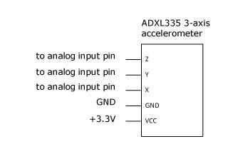
The ADXL335 is a 3 axis accelerometer used in the vehicle to measure x, y and z co-ordinate axis [21]. As mentioned earlier, it is small in size and consumes less power as it is MEMS based accelerometer. It is a complete 3-axis accelerometer with signal conditioned voltage outputs. This measures acceleration with a minimum full-scale range of ±3g with low power consumption of 350 µA. This MEMS ADXL335 provides better temperature co-efficient and linearity is better compared to the ADXL3XX series. It measures both the static acceleration due to gravity in titling position and dynamic acceleration during motion, shock and vibration. The pin diagram of the ADXL335 is shown in the Figure 9 below.
Figure 9. Pin diagram of ADXL335
The Steps involved to interface the components are: Initially, connect the accelerometer on the board. The supply voltage of 3.3 V and GND pins of ardunio is connected to the ADXL335.Connect the Xout, Yout and Zout pins of ADXL335 pins to analog pins A1, A2 and A3 respectively. Read the analog outputs of each axis and print them in the serial monitor respectively. Provide a delay of 1 second for each reading. Upon executing, the readings of x, y and z axis are displayed in the serial monitor respectively with a delay of 1 second for every reading.
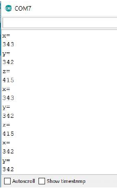
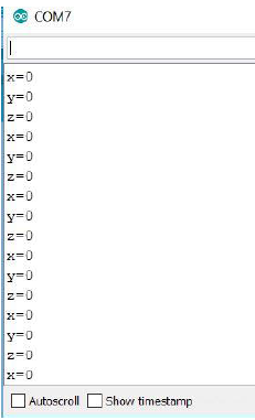
Figure 10. Output of ADXL335 before and after Calibration using Serial Monitor
The anlaog output of x, y and z axes of the accelerometer are obtained as some random values. But to use for vehicle accident application, the accelerometer must be calibrated to provide standard values. To avoid such random values the calibration is done. Based ‘n’ samples of each axis calculate their average at every reset. Now the readings are assignment as follows
Xvalue = Xvalue - Xaverage
Yvalue = Yvalue - Yaverage
Zvalue = Zvalue – Zaverage
By employing the above logic, the accelerometer is calibrated and corresponding value is uploaded in the serial monitor as shown in the Figure 10. The main parameters of ADXL335 considered for the proposed system is shown in the Table 2.
Table 2. Specification of ADXL335 sensor
|
S. No. |
Specification |
Range |
|
1 |
Voltage |
1.8 – 3.6 V |
|
2 |
X-axis |
0.5 -1600 Hz |
|
3 |
Y-axis |
0.5 – 1600 Hz |
|
4 |
Z-axis |
0.5 – 550 Hz |
|
5 |
Acceleration (Any Axis, Unpowered, Powered) |
10,000 g |
|
6 |
Current Consumption |
350 µA |
The readings of the accelerometer is taken and analysis is done for simple vehicle based on different incidences such movement in left, right, up and down at different directions is shown in the Table 3.
Table 3. Readings of accelerometer
|
Parameters |
X -Axis |
Y -Axis |
Z -Axis |
|
X-Axis titling |
70 |
50 |
45 |
|
Y-Axis titling |
50 |
70 |
45 |
|
Z-Axis titling |
50 |
60 |
70 |
|
Vibration |
70 |
70 |
70 |
|
Abnormal Motion |
90 |
90 |
90 |
|
Sitting |
20 |
30 |
35 |
|
Normal Motion |
45 |
50 |
50 |
From this above table, the proposed algorithm assumes the normal operation mode value lies in the order of +50 to -50. For an instance, if the maximum value of any axis for the vehicle to be stable is given as +50 and the minimum value as -50, whenever the accelerometer is found to be crossing these upper and lower limits, the system senses the sudden change and continues to proceed with the further functions.
3.2 GPS module
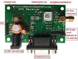
The Global Positioning System is a most popular component to track the location of the car and other location for various applications. It is embedded with the antenna to track the signals at a narrow band. The button cell used to redundant the last position. The antenna can be connected easily with GPS. The main four pins are Tx, Rx, VCC and GND connected to a [22].
The board application of GPS is position, navigation and pointing the time of a particular location. The receiver in GPS is used to receive signals to module and determine the vehicle present position and point the correct latitude, longitude and altitude of the vehicle [23, 24]. The pictorial representation of SIM28ML GPS is shown in the Figure 11.
Figure 11. Model of SIM28ML GPS
When interfacing with ardunio the common library file to extract the data is shown below. The TinyGPS++ library which does the extraction of individual parameters from NMEA sentences sent by the GPS module. It uses functions to display individual parameters such as:
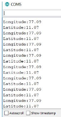
The ardunio serial monitor screen displays the latitude and longitude of a location. The serial monitor diaplay for latitude and longitude is shown in the Figure 12.
Figure 12. Output of GPS module
The range of voltage, frequency, signal level and accuracy of SIM28ML GPS is shown in the Table 4.
Table 4. Specification of SIM28ML GPS
|
S. No. |
Specification |
Range |
|
1 |
Voltage |
2.8 – 4.3 V |
|
2 |
Antenna Frequency range |
1575 MHz |
|
3 |
GPS signal level |
-130 dBm |
|
4 |
Accuracy |
2.5m CEP |
3.3 GSM module
The Global System for Mobile communications (GSM) commonly available in India market with a flexible cellular network to transmit voice call and large data services. For transmitting signals, GSM uses narrow band TDMA. This TDMA assigns on same frequency for different time slots for different users. Here, GSM is used to send the information regarding vehicle accidents via SMS using AT commands. The SIM900A GSM module is top-viewed as shown in the Figure 13.
Figure 13. SIM900A GSM module
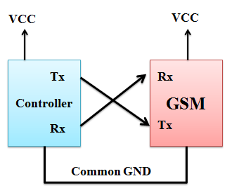
This SIM900A works with a set of AT commands. These AT commands usually operated using UART / Serial protocol. It has Tx, Rx, VCC and GND [25-27]. The interface of GSM module with the controller is shown in the Figure 14.
This GSM is embedded with all hardware interfaces between the module and customer’s boards. It is also easier to develop user’s application using serial port, audio channel with microphone, receiver output, programmable general purpose input and output pins and debug port with keypad and SPI display interfaces [28]. The specification of SIM900A GSM Module is shown in the Table 5.
Figure 14. Interfacing GSM module with controller
Table 5. Specification of GSM Module
|
S. No. |
Specification |
Range |
|
1 |
Voltage |
3.3 – 5.5 V |
|
2 |
Baud rate |
115200 bps |
|
3 |
Communication Protocol |
UART |
|
4 |
AT commands for Control |
(GSM 0X.0X, 0X.0X and SIMCOM enhanced AT Commands) |
|
5 |
Dual band GSM/GPRS |
900/1800 MHz |
|
6 |
Operating voltage |
+12 V DC |
|
7 |
Current Rating |
Maximum 12 A |
3.4 Controller
The NODE MCU is a scorching open source development kit on Internet of Things platform. The main advantage of using NODEMCU is easily available in market with inbuilt- Wi-Fi module ESP8266 – 12E. Thus the Controller makes this system mores easier, smaller, less costly and low power consumer as compared to other methods as compared Figure 2 in comparison methods [28]. It is more powerful with high level I/O pins and Digital pins. The major parameter for NODE MCU controller is shown in the Table 6.
Table 6. Specification of NODEMCU controller
|
S. No. |
Specification |
Range |
|
1 |
Frequency Range |
2.412 - 2.484 GHz |
|
2 |
Wireless Form |
On-board PCB Antenna |
|
3 |
Operating Voltage |
3.3 V Operated |
|
4 |
IO Capability |
UART, I2C, PWM, GPIO, 1 ADC |
|
5 |
Working Current |
12 - 200 mA |
|
6 |
Operating Temperature |
-40 to +125 ºC |
|
7 |
Network |
Protocol IPv4, TCP |
|
8 |
Frequency Range |
2.412 - 2.484 GHz |
3.5 AMRSC
Accidents Monitoring and Rescue Services Centre (AMRSC) is a group of servers maintained at a single place allocated for a region. AMRSC monitors all the accidents occurring in the particular region. The rescue services for this region are also controlled by AMRSC.
All the accidents are reported to AMRSC by the proposed detection system and thus AMRSC responds with the rescue services. Thus, the difficulties are reduced in this, as compared to the present system as it is controlled at a single centre [29, 30]. The Internet of Things (IoT) is the network of devices that contains electronics, software and sensors that allows connecting and exchanging of data without requiring human-human or human-computer interaction as shown in the Figure 15.
Figure 15. Cloud server data
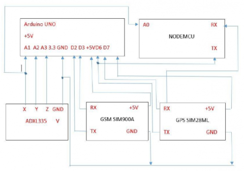
Whenever an accident occurs, the accelerometer detects the changes in the conditions and the controller does the necessary actions. The controller analyses the reading from ADXL-335 sensor. In this system, whenever the position value falls above 50 or below -50 it confirms that the accident has occurred. The circuit diagram of the proposed system is shown in the Figure 16.
Figure 16. Circuit diagram of the proposed system
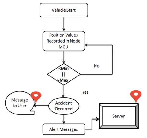
Figure 17. Flow chart of the proposed system
Now, the GPS detects the location and the GSM sends a pre-set message to the number which has been given in the code. In automatic accident indication and reporting system for road ways using Internet of Things system, the GPS data is also sent to the Thing speak server and this data can be analysed and the authorities can decide whether a particular location is an accident prone area.
The flow chart in the Figure 17 shows the working of the accident indication and reporting system.
The result of the proposed system is analyzed based on the above flow chart Figure 17.
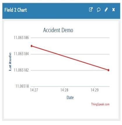
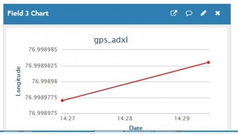
The accelerometer values are recorded continuously and the change value is sensed by controller. The controller gives signal to both the user and AMRSC. The Figure 18 and 19 shows the accident occurred location (i.e. latitude and longitude with date) using IoT platform.
Figure 18. Latitude Readings taken from the server
The Figure 18 and 19 displays, the data taken from the server for an event when the object suddenly hits another object with a deviation mentioned in the controller.
Figure 19. Longitude Readings taken from the server
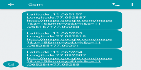
The Figure 20 shows the message of accident occurred location (i.e. latitude and longitude with Google map link) using GSM module.
Figure 20. Alert message along with Google Map link
The location of the accident is also monitored and observed using Google map and shown in the Figure 21.
Figure 21. Accident location using Google Map
Therefore the alert message is sent to the given phone number and the details of the location is also sent to the Thingspeak server. Thus, by using IoT technology, the accident location data can be analysed and if there is a high risk of an accident taking place in a particular location, then this data will be very useful in order to analyse why that location is an accident prone region and take necessary action to reduce the number of such incidents in future [31].
The proposed system can also be extended by creating a mobile app displaying accident prone zone or making the accident prone zone display in the Google Maps.
The transport is the basic need for a commodity to move from one place to other place. Thus, there are different types of vehicles are used for transportation. The various methods of accident indication system are reviewed and consolidated. The proposed AMRSC method provides the efficient way to indicate the accident occurred location and inform the other users using message. As this data’s are connected to the cloud, the further services such as ambulance service, resume service, etc. are activated based on the requirement.
The proposed system can also be extended by implementing the following ideas:
To build Centres divided by regions, monitoring the accident activities and emergency services for the particular region.
[1] Transport and Highways Transport Research, Delhi, “Road Accidents 2016”, http://www.indiaenvironmentportal.org.in/files/file/RoadaccidentsinIndia2016.pdf, accessed on Jan. 02, 2019.
[2] Open Government Data Platform (OGD), India, https://www.nic.in/products/open-government-data-ogd-platform-india/, accessed on Jan.02, 2019.
[3] Wang, W., Fang, H. (2011). Traffic accident automatic detection and remote alarm device. 2011 International Conference on Electric Information and Control Engineering, pp. 910-913. https://doi.org/10.1109/ICEICE.2011.5777923
[4] Athavan, K., Balasubramanian, G., Jagadeeshwaran, S., Dinesh, N. (2012). Automatic ambulance rescue system. 2012 Second International Conference on Advanced Computing & Communication Technologies, pp. 190-195. https://doi.org/10.1109/ACCT.2012.34
[5] Iyyappan, Nandagopal, V. (2013). Accident detection and ambulance rescue with intelligent traffic light system. International Journal of Advanced Technology and Engineering Research, 1319-1321.
[6] Anudeep, P., Babu, K.H. (2014). Wireless reporting system for accident detection at higher speeds. Journal of Engineering Research and Applications, 4(9): 17-20.
[7] Anil, B.S., Vilas, K.A., Jagtap, S.R. (2014). Intelligent system for vehicular accident detection and notification. 2014 International Conference on Communication and Signal Processing, pp. 1238-1240.
[8] Suryakala, N., Roopa, G. (2018). IOT based vehicle tracking and accident detection system. pp. 381-386.
[9] Kushwaha, V.S., Topinkatti, A., Yadav, D., Kumari, A. (2015). Car accident detection system using GPS, GSM and Bluetooth. IJERGS, 3: 1025-1033.
[10] Ali, H.M., Alwan, Z.S. (2015). Car accident detection and notification system using smartphone. International Journal of Computer Science and Mobile Computing, 4(4): 620-635.
[11] Wang, J., Luo, T. (2019). Crash prediction based on traffic platoon characteristics using floating car trajectory data and the machine learning approach. Accident Analysis and Prevention, 133: 105320. https://doi.org/10.1016/j.aap.2019.105320
[12] Mercader, P., Haddad, J. (2020). Automatic incident detection on freeways based on Bluetooth traffic monitoring. Accident Analysis and Prevention, 146: 105703. https://doi.org/10.1016/j.aap.2020.105703
[13] Wang, Y., Bialkowski, K.S., Pretorius, A.J., du Plooy, A.G.W., Abbosh, A.M. (2018). In-road microwave sensor for electronic vehicle identification and tracking: Link budget analysis and antenna prototype. IEEE Transactions on Intelligent Transportation Systems, 19(1): 123-128. https://doi.org/10.1109/TITS.2017.2690679
[14] John, A., Nishanth, P.R. (2017). Real time embedded system for accident prevention. 2017 International conference of Electronics, Communication and Aerospace Technology (ICECA), pp. 645-648. https://doi.org/10.1109/ICECA.2017.8212745
[15] Kinage, V., Patil, P. (2020). IoT based intelligent system for vehicle accident prevention and detection at real time. 2019 Third International conference on I-SMAC (IoT in Social, Mobile, Analytics and Cloud) (I-SMAC), pp. 409-413. https://doi.org/10.1109/I-SMAC47947.2019.9032662
[16] Mahamud, M.S., Monsur, M., Zishan, M.S.R. (2017). An arduino based accident prevention and identification system for vehicles. 2017 IEEE Region 10 Humanitarian Technology Conference (R10-HTC), pp. 555-559. https://doi.org/10.1109/R10-HTC.2017.8289021
[17] Manna, S., Bhunia, S.S., Mukherjee, N. (2014). Vehicular pollution monitoring using IoT. International Conference on Recent Advances and Innovations in Engineering (ICRAIE-2014), pp. 1-5. https://doi.org/10.1109/ICRAIE.2014.6909157
[18] Goh, K.N., Jaafar, J., Goh, E. (2014). Automatic accident location detection system (AALDS). 2014 4th World Congress on Information and Communication Technologies (WICT 2014), pp. 63-69.
[19] Amin, M.S., Bhuiyan, M.A.S., Reaz, M.B.I., Nasir, S.S. (2013). GPS and Map matching based vehicle accident detection system. 2013 IEEE Student Conference on Research and Development, pp. 520-523. https://doi.org/10.1109/SCOReD.2013.7002645
[20] Nasr, E., Kfoury, E., Khoury, D. (2016). An IoT approach to vehicle accident detection reporting and navigation. 2016 IEEE International Multidisciplinary Conference on Engineering Technology (IMCET), pp. 231-236. https://doi.org/10.1109/IMCET.2016.7777457
[21] Analog Devices, ―Small, Low Power, 3-Axis ±3 gAccelerometer‖,ADXL335 Datasheet, Jan 2009.
[22] Global Positioning System‖, in Wikipedia the free encyclopedia. https://en.wikipedia.org/wiki/Global_Positioning_System, accessed on 12 Feb., 2019.
[23] Desai, V.J. (2019). Design and implementation of GSM and GPS based vehicle accident detection system. International Research Journal of Engineering and Technology (IRJET), pp. 1-4.
[24] Prabha, C., Anitha, R. (2014). Automatic vehicle accident detection and messaging system using GSM and GPS modem. International Journal of Advanced Research in Electrical, Electronics and Instrumentation Engineering, 1-5.
[25] SIMCOM, ―SIM28ML_Hardware Design_V1.01‖,SIM28ML Datasheet, March 2014.
[26] GSM‖, in Wikipedia the free encyclopedia. Available: Wikipedia [Online], https://en.wikipedia.org/wiki/GSM, accessed on 12 Feb., 2019.
[27] SIMCOM, ―SIM900_Hardware Design_V2.05‖, SIM900A Datasheet, Dec 2009, accessed on 12 Feb., 2019.
[28] Einstronic ―Introduction to NodeMCU ESP8266‖, NodeMCU Datasheet, July 2017.
[29] Amin, M.S., Bhuiyan, M.A.S., Bin Ibne Reaz, M., Nasir, S.S. (2013). GPS and Map matching based vehicle accident detection system. 2013 IEEE Student Conference on Research and Developement, pp. 520-523. https://doi.org/10.1109/SCOReD.2013.7002645
[30] Wakure, A.R., Patkar, A.R., Dagale, M.V., Solanki, P.P. (2014). Vehicle accident detection and reporting system using GPS and GSM. IJERGS, 10(4): 25-28.
[31] Marimuthu, M., Sirushti, K. (2018). Accident detection and reporting system using Internet of Things. Research Journal of Science and Engineering Systems, 3(2): 121-129.