Pedro N. Oliveira | Elza M.M. Fonseca* | Raul D.S.G. Campilho
© 2020 IIETA. This article is published by IIETA and is licensed under the CC BY 4.0 license (http://creativecommons.org/licenses/by/4.0/).
OPEN ACCESS
This work presents the calculation of the temperature in different cross-sections of structural profiles (IPE, HEM, L and UAP) using the lumped capacitance method and the simplified equation from Eurocode 3 part 1-2. The lumped capacitance method allows the temperature calculation of the solid body at any time instant during the heat transient process, as a constant and uniform value. The simplified equation from Eurocode 3 part 1-2 is a simple model for heat transfer based on the uniformly distributed temperature over the cross-section surface and directly proportional to section factor of the element. Steel profiles have as almost thermal behaviour uniform during the heat transfer process when submitted to fire conditions and the lumped capacitance method allows a great simplification to estimate the temperature field in the element and may be used when Biot number is lower than unity. Therefore, thermal analysis of solids with high thermal conductivity using this method is adequate. For the studied steel profiles, a thermal analysis was also performed using the simplified equation from the Eurocode 3 part 1-2 in order to validate the obtained results from the lumped capacitance method. The results from both methods are presented for discussion and analysis.
lumped capacitance method, simplified equation, steel profiles, heat transient process, fire
Transient conduction is a process of heat transfer by conduction in a non-stationary regime that depends on the elapsed time. Some solids, especially metals with high thermal conductivity, have an almost uniform temperature distribution in the cross-section area during a heat transfer process, for any time instant throughout the transient process, in such a way that the temperature is exclusively function of time. Any thermal analysis that uses this idealization can be performed using the lumped capacitance method [1-4].
The European standards also represent simplified expressions for the temperature calculation of steel structures exposed to high temperatures. The presented simplified models are depending on a given number of thermal parameters, boundary conditions and cross-section shape parameters [5]. These parameters are most frequently determined by experiments, developed by different researchers [5].
Easy trends to analyse structural steel profiles submitted to fire could help engineers in their building design. Fire is a very complex phenomena and can cause severe structural damages. Some numerical techniques with high performance are also available for this type of analyses, with major contributions being given in references [6-10]. Also, fire resistance tests are frequently used to evaluate the fire resistance in structural components protected or unprotected [11-13].
Different comparisons between numerical and experimental methods are produced to ensure valid proposals as a guide to follow in structural buildings under fire. Design criteria for profiles safety require assumptions in structural and heating models. It is considered that structural damage occurs when the structural resistance reduces to the applied fire action. In comparison with other materials, steel elements have a critical behaviour due to the very high thermal conductivity.
The main objective of this paper is to calculate the temperature distribution in a solid profile cross-section area, in relation to time, during a transient process and to verify the heat transfer between the solid and environment. In this study different ranges of hot-rolled steel profiles have been studied (IPE, HEM, L and UAP), submitted to fire at all four sides, to verify the temperate distribution in transient regime and the influence of the size of the profile in thermal behaviour of these steel members, using the lumped capacitance method and the simplified equation from Eurocode 3 part 1-2 [14]. In this manuscript, it intends to present the lumped capacitance method applied to any steel profiles, according the section factors effect that will impose a different behaviour in the heating profile. The results obtained from this method are very close to the obtained from the simplified equation. This find enabled to conclude that this methodology appears as an easily tool to calculate the temperature evolution in hot-rolled steel profiles submitted to fire.
The increase of temperature in the cross-section area for an unprotected hot-rolled steel profile submitted to fire, during a time interval $\Delta t$, must be determined from the simplified equation presented in Eurocode 3 part 1-2 [14]:
$\Delta {{\theta }_{a,t}}={{k}_{sh}}\frac{{{A}_{m}}/V}{{{C}_{a}}\rho }{{\dot{h}}_{net,d}}\Delta t$ (1)
The where ksh is the correction factor for the shadow effect [14], and is considered equal to unity for conservative results, Am is the surface area of the member per unit length [m2/m] [14], V is the volume of the steel member per unit length [m3/m] [14], Am/V is the section factor for unprotected steel members [m-1] as calculated in Table 1 [14], Ca is the specific heat of steel, calculated according to the Eurocode 3 part 1-2 [14], ρ is the density of steel, which may be considered equal to 7890 [kg/m3] according to the Eurocode 3 part 1-2 [14], $\Delta t$ is the time interval which must not be taken as more than 5 seconds [14] and hnet,d is the net heat flux [W/m2], due to radiation and convection per unit area, which should be determined according to the Eurocode 1 part 1-2 [15] by the following expression:
${{\dot{h}}_{net,d}}={{\dot{h}}_{net,c}}+{{\dot{h}}_{net,r}}$ (2)
$\dot{h}_{ {net}, c}$ is the net convective heat flux component per unit area [W/m2] [15], $\dot{h}_{ {net}, r}$ is the net radiative heat flux per unit surface area [W/m2] [15] and their values must be obtained from the Eqns. (3) and (4), respectively.
${{\dot{h}}_{net,c}}={{\alpha }_{c}}({{\theta }_{\infty }}-{{\theta }_{m}})$ (3)
$\alpha_{c}$ is the coefficient of heat transfer by convection and should be taken as 25 [W/m2K] [15], $\theta_{\infty}$ is the gas temperature in the vicinity of the fire exposed steel member and $\theta_{m}$ is the surface temperature of the steel member [15].
${{\dot{h}}_{net,r}}=\phi .{{\varepsilon }_{m}}.{{\varepsilon }_{f}}.\sigma .[{{({{\theta }_{r}}+273)}^{4}}-{{({{\theta }_{m}}+273)}^{4}}]$ (4)
$\phi$ is the configuration factor, which must be taken equal to unity [15], $\varepsilon_{m}$ is the surface emissivity of the member taken as equal to 0,7 [15], $\varepsilon_{f}$ is the emissivity of the fire, generally taken as equal to unity [15], $\sigma$ is the Stephan Boltzmann constant, taken as 5,67x10⁻⁸ [W/m2K4] [15], and $\theta_{r}$ is the effective radiation temperature of the fire environment of the steel member [15], being often considered that $\theta_{r}=\theta_{\infty}$.
The environment temperature evolution, due fire exposed in all four sides of the steel member, in [℃], is given by the standard temperature time curve ISO 834 [15, 16] according the following equation:
${{\theta }_{\infty }}=20+345{{\log }_{10}}(8t+1)$ (5)
where, t is the time, in [min].
The lumped capacitance method is a simplest transient heat conduction approach, which permits to analyze the temperature of the hot-rolled steel members only as a function of the time. For application of this method, the temperature of a solid is assumed to be spatially independent or uniform [17].
Therefore, a relatively uniform temperature distribution within the solid is assumed when compared to the temperature distribution between the body and the environment [17]. This hypothesis can be made if the resistance to the heat conduction within the solid is small in comparison to the heat transfer resistance between the solid and ambient [17]. This assumption is according the calculated Biot number (Bi) [2, 4].
The Biot number is a dimensionless heat transfer coefficient and is defined as the ratio of the convection and the conduction thermal resistances, according to Eq. (6) [17].
${{B}_{i}}=\frac{{{L}_{c}}\text{ }{{\alpha }_{cr}}}{{{\lambda }_{a}}}$ (6)
Lc is the solid characteristic length, in [m-1], defined as the ratio between the solid volume and the cross-section area exposed to fire, and equal to the inverse of the section factor, $\lambda_{s}$ is the steel thermal conductivity, in [W/mK], and should be determined according to the Eurocode 3 part 1-2 as a function of temperature [14], and $\alpha_{c r}$ is the heat transfer coefficient of convection and radiation [W/m2K], which is given by the sum of the heat transfer coefficient by convection and the heat transfer coefficient by radiation, $\alpha_{r}$, which must be calculated according to the following equation:
${{\alpha }_{r}}=\varepsilon \sigma (\theta +{{\theta }_{\infty }})({{\theta }^{2}}+\theta _{\infty }^{2})$ (7)
To apply this method to solids submitted to fire, it is necessary to consider the radiation heat transfer since a large part of the heat flow transferred to the steel members is through radiation [18].
The use of this method is generally accepted when the Biot number is smaller than unity [19]. When this criterion is satisfied the temperatures within the solid relative to the surroundings remain in 5% variation, whereby the temperature range will be minor and can reasonably to be uniform [19]. In this situation, the resistance to conduction within the solid is much less than the resistance to convection in the surface immediate vicinity. Which allow to conclude, that the hypothesis of a uniform temperature distribution is reasonable [2]. Therefore, solid bodies with high thermal conductivity, as in case of steel, are good candidates for the use of this method. If the temperature in the solid cross-section area is considered to be uniform, that is $\theta_{x, t} \cong \theta_{t}$, the solution of Eq. (8) allows to obtaining the temperature as a function of time.
${{\theta }_{t}}=({{\theta }_{i}}-{{\theta }_{\infty }}){{e}^{(-Bi.Fo)}}+{{\theta }_{\infty }}$ (8)
$\theta_{t}$ is the temperature for a time t, $\left(\theta_{i}-\theta_{\infty}\right)$ is the temperature difference at time t=0 and Fo is the Fourier number.
The Fourier number is a dimensionless ratio between the heat conducted through the solid and the heat retained by the solid.
A high Fourier number value indicates a faster heat spread through a solid body, and it is calculated for a time after step change in ambient temperature, according to the following equation:
$Fo=\frac{{{\lambda }_{a}}.t}{\rho {{C}_{a}}L_{c}^{2}}$ (9)
The results obtained from the lumped capacitance method will be presented and compared with the results obtained from the use of the simplified expressions according to the Eurocode 3 part 1-2 [14].
The temperature distribution was obtained for a time interval from 0 to 1800 seconds, using the two aforementioned methods (the lumped capacitance method - LC, and the simplified equation of the Eurocode 3 part 1-2 - EC3).
The steel cross-section area in this study was exposed to the standard fire curve, namely ISO 834, acting on the four sides of the profile.
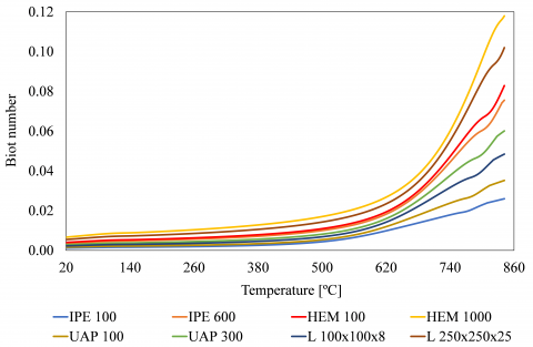
For lumped capacitance method, the Biot number was below the unit in all studies, as exemplified in Figure 1 for the minimal and maximum hot-rolled profile in each type. Also, the characteristic length, equal to the inverse section factor, was determined for all members, see Table 1.
In Table 1, the section factor for unprotected steel members allows to measure the rate temperature increase of a steel cross-section area by the ratio of the heated surface to the volume.
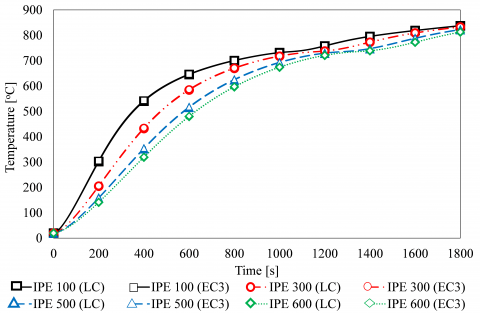
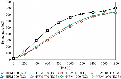
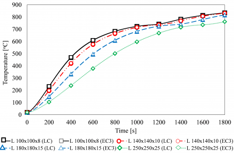
The temperature distribution in different 16 hot-rolled steel profiles, according the applied two methodologies, are represented in Figures 2 to 5.
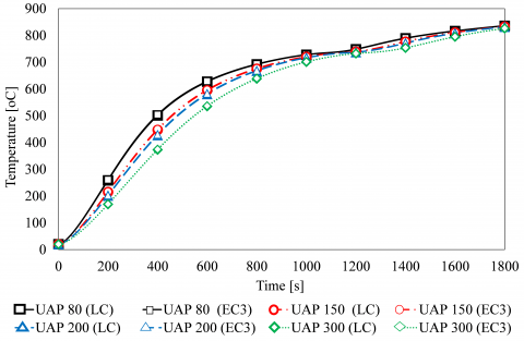
It was possible to analyse the temperature-time history for different sizes of the studied hot-rolled steel profiles. The results in Figures 2 to 5 showed that the use of the lumped capacitance method (LC) agree with the results from the simplified expression of the Eurocode 3 part 1-2 (EC3) for all different types and sizes of the studied profiles. It was possible to verify that for IPE, L and UAP hot-rolled steel profiles, when the profile size increases the temperature distribution decreases, with an exception of the HEM hot-rolled steel profile. This fact is related with the values of the section factor. In IPE, L and UAP profiles the section factor decreases when the cross-section of the profile increases. The exception is the HEM profile, the section factor decreases until HEM400, and then it increases. All these results growing the previous research of the authors, when have studied hollow tubular sections and a range of IPE profiles using numerical and analytical methodologies [1].
In all temperature-time curves of the studied steel profiles there are some similarity in a certain temperature range. This observation is in the rise of the steel temperature between 700℃ and 800℃ due to the latent heat of metallurgically phase change of the steel in this range [20]. This is the effect of the rapid increase in the specific heat material property of the steel at level of 735℃ [20].
Figure 1. Biot number calculation
Table 1. Section factor values, Am/V [m-1]
|
|
IPE100 |
IPE300 |
IPE500 |
IPE600 |
|
Am/V |
387.3837 |
215.5733 |
150.9564 |
129.1536 |
|
|
HEM100 |
HEM400 |
HEM700 |
HEM1000 |
|
Am/V |
115.9488 |
61.4993 |
66.8315 |
67.8309 |
|
|
L100x100x8 |
L140x140x10 |
L180x180x15 |
L250x250x25 |
|
Am/V |
255.4960 |
203.8704 |
138.2748 |
85.6769 |
|
|
UAP80 |
UAP150 |
UAP200 |
UAP300 |
|
Am/V |
302.8423 |
230.8237 |
210.7968 |
165.1751 |
Figure 2. Temperature-time history of IPE100 to IPE600. Agreement between LC and EC3 methods
Figure 3. Temperature-time history of HEM100 to HEM1000. Agreement between LC and EC3 methods
Figure 4. Temperature-time history of L100x100x8 to L250x250x25. Agreement between LC and EC3 methods
Figure 5. Temperature-time history of UAP80 to UAP300. Agreement between LC and EC3 methods
Figure 6. Error between LC and EC3 methods
Analyzing the graphs, the temperature values are very close for any profile size using the two methodologies. The error between the lumped capacitance method and the simplified equation of the Eurocode 3 part 1-2 in relation to the same Eurocode expression was calculated for all studied profiles. Figure 5 represents the obtained maximum error during the time interval from 0 to 1800 seconds for each hot-rolled profile type. It is possible to verify that the error decreases with the increase in the cross-section of the profile, and always is lesser than 1%.
In this present study, as a conclusion, cross-section area of a hot-rolled steel profile with low section factors will heat up more slowly, as referenced by Paroc [21].
There are some analytical and easy methods for temperature evaluation in solid bodies. These methods could be used by engineers due their simplicity and the good results.
In this work, the results obtained from the lumped capacitance method were compared with the results using the simplified expression from the Eurocode 3 part 1-2. It was found that the results from the lumped capacitance method present values very close to those obtained from the simplified equation. This find enabled to conclude that the lumped capacitance method is trustworthy and could be easily applied to these type of hot-rolled steel profiles.
Since 16 profiles were studied, it was possible to conclude that, for IPE, L and UAP profiles, the larger the profile size the lower the temperature field along the cross-section area. For HEM profiles, the same trend was not verified as the HEM 1000 has a higher temperature distribution over the cross-section area than the HEM 400.
Members with low section factors will heat up slow. As a conclusion, the section factor measures the rate at which a cross-section area will heat up, in a fire and, the higher its value, the greater will be the needed protection panel.
For future work a section factor including the shadow effect should be considered. The shadow effect is produced by the local shielding of irradiative heat transfer, due to the steel profile configuration. In this work, the shadow effect was considered equal to unit.
|
$k_{s h}$ |
correction factor for the shadow effect |
|
$A_{m} / V$ |
section factor |
|
$C_{a}$ |
specific heat |
|
$\dot{h}_{\text {net}, d}$ |
net heat flux |
|
$\Delta t$ |
time interval |
|
$\dot{h}_{\text {net, c}}$ |
net convective heat flux |
|
$\dot{h}_{\text {net, r}}$ |
net radiative heat flux |
|
t |
time |
|
Lc |
characteristic length |
|
Bi |
Biot number |
|
Fo |
Fourier number |
|
Greek symbols |
|
|
$\Delta \theta_{a, t}$ |
increase of temperature |
|
$\rho$ |
density |
|
$\alpha_{c}$ |
coefficient of heat transfer by convection |
|
$\theta_{\infty}$ |
gas temperature |
|
$\theta_{m}$ |
surface temperature |
|
$\phi$ |
configuration factor |
|
$\varepsilon_{m}$ |
surface emissivity |
|
$\varepsilon_{f}$ |
emissivity of the fire |
|
$\sigma$ |
Stephan Boltzmann constant |
|
$\theta_{r}$ |
radiation temperature |
|
$\theta_{\infty}$. |
environment temperature evolution |
|
$\lambda_{s}$ |
thermal conductivity |
|
$\alpha_{c r}$ |
coefficient of heat transfer by convection and radiation |
|
$\alpha_{r}$ |
coefficient of heat transfer by radiation |
|
$\theta_{t}$ |
temperature for a time |
[1] Fonseca, E. (2013). Thermal analysis of hollow tubular sections under high temperatures. Frontier of Engineering Mechanics Research, 2(1): 9-14.
[2] Incropera, F.P., DeWitt, D.P., Bergman, T.L., Lavine, A.S. (2007). Fundamentals of Heat and Mass Transfer. John Wiley & Sons, USA.
[3] Xu, B., Li, P.W., Chan, C.L. (2012). Extending the validity of lumped capacitance method for large Biot number in thermal storage application. Solar Energy, 86(6): 1709-1724. https://doi.org/10.1016/j.solener.2012.03.016
[4] Baglio, S., Castorina, S., Fortuna, L., Savalli, N. (2002). Modeling and design of novel photo-thermo-mechanical microactuators, Sensors and Actuators A: Physical, 101(1-2): 185-193. https://doi.org/10.1016/S0924-4247(02)00200-5
[5] Boko, I., Torić, N., Peroš, B. (2012). Analysis of heat transfer design models based on EN1993-1-2. GRAĐEVINAR, 64(4): 285-292.
[6] Fonseca, E.M.M., Leite, P.A.S., Silva, L. (2020). Wood connections under fire conditions protected with gypsum plasterboard types A and F. In: Piloto P., Rodrigues J., Silva V. (eds) Advances in Fire Safety Engineering. CILASCI 2019. Lecture Notes in Civil Engineering, vol 1. Springer, Cham. https://doi.org/10.1007/978-3-030-36240-9_7
[7] Fonseca, E.M.M., Silva, L., Leite, P.A.S. (2020). Numerical model to predict the effect of wood density in wood–steel–wood connections with and without passive protection under fire. Journal of Fire Sciences, 38(2): 1-14. https://doi.org/10.1177/0734904119884706
[8] Couto, D.L.P., Fonseca, E.M.M., Piloto, P.A.G., Meireles, J.M., Barreira, L.M.S., Ferreira, D.R.S.M. (2016). Perforated cellular wooden slabs under fire: numerical and experimental approaches. Journal of Building Engineering, 8: 218-224. https://doi.org/10.1016/j.jobe.2016.10.007
[9] Fonseca, E.M.M., Coelho, D.C.S., Barreira, L.M.S. (2012). Structural safety in wooden beams under thermal and mechanical loading conditions. International Journal of Safety and Security Engineering, 2(3): 242-255. https://doi.org/10.2495/SAFE-V2-N3-242-255
[10] Fonseca, E.M.M., Barreira, L. (2011). Experimental and numerical method for determining wood char-layer at high temperatures due an anaerobic heating. International Journal of Safety and Security Engineering, 1(1): 65-76. https://doi.org/10.2495/SAFE-V1-N1-65-76
[11] Marek, Ł., Piotr, T., Paweł, R., Bartłomiej, P. (2017). Fire resistance of unprotected steel beams - comparison between fire tests and calculation models. Procedia Engineering, 172: 665-672. https://doi.org/10.1016/j.proeng.2017.02.078
[12] Wnag, Y., Chuang, Y.J., Lin, C.Y., Zhang, H. (2018). The standard fire testing and numerical modelling of the behavior of calcium silicate board metallic-framework drywall assembly with junction box. Advances in Materials Science and Engineering, 2018: 1-13. https://doi.org/10.1155/2018/8130647
[13] Yang, J., Shao, Y.B., Chen, C. (2014). Experimental study on fire resistance of square hollow section (SHS) tubular T-Joint under axial compression. Advanced Steel Construction, 10(1): 72-84. https://doi.org/10.18057/IJASC.2014.10.1.5
[14] EN1993-1-2. (2010). Eurocode 3: Design of steel structures - Part 1-2: General rules - Structural fire design. European Committee for Standardization. Brussels.
[15] EN1991-1-2. (2010). Eurocode 1: Actions on structures - Part 1-2: Structural fire design. European Committee for Standardization. Brussels.
[16] ISO 834-1. (1999). Fire Resistance Tests - Elements of building Construction - Part 1: General Requirements. International Organization for Standardization. Switzerland.
[17] Wojtkowiak, J. (2014). Lumped thermal capacity model. In: Hetnarski R.B. (eds) Encyclopedia of Thermal Stresses. Springer, Dordrecht. https://doi.org/10.1007/978-94-007-2739-7_393
[18] Hurley, M.J., Gottuk, D.T., Hall Jr., J.R., Harada, K., Kuligowski, E.D., Puchovsky, M., Torero, J.L., Watts Jr., J.M., Wieczorek, C.J. (2015). SFPE Handbook of Fire Protection Engineering. Fifth Edit. Massachusetts.
[19] Holman, J.P. (2019). Heat Transfer. McGraw-Hill, New York.
[20] Franssen, J.M., Vila Real, P. (2015). Design of Steel Structures. Second Edit. ECCS Eurocode Design Manuals.
[21] Paroc, L.T.D. Fire protection guide steel. Technical Insulations Division. Paroc Group. https://www.paroc.com/, accessed on June 8, 2020.