Arief Goeritno* | Dudi Nurmansyah | Maswan
© 2020 IIETA. This article is published by IIETA and is licensed under the CC BY 4.0 license (http://creativecommons.org/licenses/by/4.0/).
OPEN ACCESS
This paper explains the SIS to investigate the system of instrumentation and process control on the steam purification systems in the geothermal power plant. The research objectives include (i) analysis based on SIL against the BPCS, (ii) determining the component specifications of SIS, (iii) the design of SIS in the form of drawing, and (iv) simulation aided the application of PLC Simulator against the design of SIS result. Analysis step based on SIL conducted on the existence of BPCS. There are two potential danger of SIL-2, namely the condensate water entered the turbine and the steam pressure drop. The component specification is a consideration for the installation of two actuators with a redundant system. The design of SIS in the form of drawing namely the investigating for the instrumentation and process control through the block diagram, so that the function of the SIS as a protection system against personal safety, environmental, and operating facilities, in addition to the publication of the company's reputation. The simulation against the design of development results namely the conditioning of the operation of the emergency valve for drain to the gain of certainty, that the valve is opened when signals from LSH or logic 1 is received and the valve is closed again after signal reception from LSL or logic 0, so the valve can be operated in accordance with logic operation 1 and 0.
safety instrumented systems, system of instrumentation and process control, purification system of the steam, geothermal power plant
An acronym or abbreviation as SIS that used in a functional safety is a set of devices and software that perform of one or more of SIF [1, 2], so that important to ensure the safe operation of a system in general [3]. Existence of the SIS is specifically designed to protect personal, equipment, and environment through reducing the likelihood or severity of the impact of an identified emergency event [1, 2, 4-6]. Usefulness of SIS when operated for any action is to prevent or reduce risk during processing under abnormal conditions that may be dangerous [1-6]. The SIS is embedded in the system for industrial control and automation along with the BPCS [7]. It is a development of a conventional process of SIS-based. A conventional process control on plant or the others, often comprised of a set of software black boxes, accessible only by specialized personnel and a very limited number of highly technical [8].
A SIS assessment is conducted to identify any gaps that critical and potential between SIS best practice and IEC 61511 requirements through the design and implementation, so that the operation as well as the maintenance of the SIS existing [1]. The findings of the assessment will be categorized on their impacts to the safety, business as well as environment, and will be used as a basis for opportunity improvement of the SIS. All findings with recommendations that have impact shall be documented, tracked, followed-up, and finished out [2].
Dividing in the sequential steps as defined in the IEC-61508 is the procedure for the implementation of SIS [2], namely (1st step) concept, (2nd step) overall SIS scope definition, (3rd step) hazard and risk analysis, (4th step) overall safety requirements, (5th step) safety requirement allocation, (6th step) SIS operation and maintenance plan, (7th step) safety validation plan, (8th step) installation and commissioning plan, (9th step) SIS detailed design, (10th step) other technologies, (11th step) external risk reduction, (12th step) overall installation and commissioning, (13th) overall safety validation, (14th step) SIS operation, maintenance and testing, (15th step) overall modification and retrofit, and (16th step) de-commissioning or disposal. This procedure to achieve an intended safety function up to field installation and commissioning that shall be applicable for the company [2]. For the design and implementation of the SIS, IEC-61508 standards with a number of working procedures are adopted [2].
The SIS is composed of several safety functions, so it is an implementation of SIF [1-18]. Schematic diagram of SIF [6] is shown in Figure 1.
Based-on Figure 1 explained, that the SIS is the system that consists of sensors, logic solver (determiners of logic), and the final control element [1-18] that is designed and installed for taking the process for achievement safe state due to failure of the instrumentation and the system of process control. When a large potential occurs and results in a real loss, that's where the SIS are is used to provide safe insulation against flammable or toxic materials that have the potential to cause a fire or incident liquid wasted into the environment [10-13]. Listing the device provider of Safety Requirements Specification (SRS) is a requirement and linkage requested by Industrial Standard Architecture (ISA) 84 Clause 10.3.1 [4, 14, 15]. If each SIF that hasn’t been verified would meet the target Safety Integrity Level (SIL) specified during the SIL classification performed during design or assessment, then determined by the SIL verification [16, 17].
Figure 1. Schematic diagram of SIF
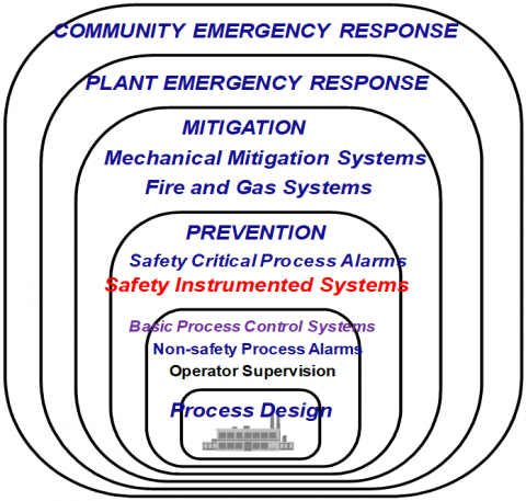
Safety is provided by a protective layer. These layers begin with safe and effective process control, extend to the manual and automatic prevention layers, and continue with layers to reduce the consequences of the systems of instrumentation and process control failure event [1, 2, 4, 5]. The protective layer is known as Independent Protection Layers (IPL) which are bound as onion skins, where each layer is independent in the terminology of operation and failure of one layer does not affect the next layer. Schematic diagram of the IPL [5, 6] is shown in Figure 2.
Figure 2. Schematic diagram of the IPL
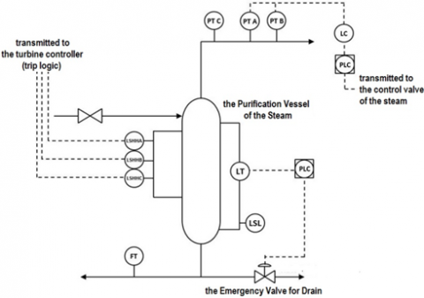
The system of instrumentation and process control is one of the brightest fields since a few decades ago until today [18]. The objectives of the operation of a system of instrumentation and process control are to maximize in (i) productivity, (ii) optimization, (iii) stability, (iv) reliability, (v) safety, and (vi) continuity [18]. The purification system of the steam is one of the main processes in the steam production system in the Geothermal Power Plant [19-21]. In this system is used the system of instrumentation for the process control. Its role is so critical, because it is the last facility as a supplier of steam to turbines [21]. Steam conditions with requirements, both in terms of quality and quantity absolutely must be met [21]. One important aspect that must be done to achieve these conditions, is done through ensuring that the systems of instrumentation and process control can operate properly and minimize all potential disruptions caused by malfunctioning of the control system [22, 23]. All process and control system in the purification system of the steam are operated according to the BPCS standard [24]. Example case of the schematic diagram of BPCS placement on a purification system of the steam in the geothermal power plant [19-21] is shown in Figure 3.
Figure 3. Example case of the schematic diagram of BPCS placement on a purification system of the steam in the geothermal power plant
Based-on Figure 3 can be explained, that the height of the condensate water in the vessel is detected by a level transmitter with a type of differential pressure (d/p LT) with a reading limit from 0 to 100%. Normal operating conditions, the height of the condensate in the vessel wins below 10%. The result of LT detection is a 4-20 mA (analog signal) transmitted to the BPCS controller, i.e. the Programmable Logic Controller (PLC). The input signal is needed by the PLC into two output signals. The first output signal is an analog output signal transmitted to the control room for remote reading by the operator. The second output signal in the form of a digital output consisting of codes 1 or 0 transmitted to an emergency transfer payment.
The type of drive on the valve used is pneumatic or air pressured with an open compilation PLC transmitted code 1 when the condensate water level is detected LT when it gets 20%. The valve closure can only be done with the assistance of the operator through the control interface in the control room. The interface command is transmitted to the PLC, then the PLC sends the signal in the form of code (logistics) 0 for valve placement [22, 23]. Based on this description and the Figure 2, the implementation of the conception of safety instrumented systems for investigating the system of instrumentation and process control on the purification system of the steam in the Geothermal Power Plant was examined, through research objectives, namely: (i) analysis based-on the SIL for the development plan of SIS, (ii) components specifications of the SIS as a result of development, (iii) the SIS design is implemented in detail with the form of drawing, and (iv) performance simulation of the result of development for the system of instrumentation and process control.
2.1 Materials of research
The system of instrumentation and process control in the purification system of the steam is shown in Table 1.
Other measuring devices such as Flow Transmitter (FT) and Pressure Transmitter (PT). Flow Transmitter functions to read the condensate flow value which is released from the purification vessel to another shelter. The output signal from FT is a 4-20 mA (analog signal) transmitted to the PLC to be processed and transmitted to the control room in the form of an AO signal, while the Pressure Transmitter (PT) is used to measure vapor pressure in a steam purification vessel. There are three PTs, namely PT-A, PT-B, and PT-C. Signals from PT-A and PT-B are received by the PLC to control the desired pressure value based on the desired pressure target. While PT-C is only used for pressure reading only. All indications from the three PTs are transmitted to the control room for monitoring by the operator.
The protection system currently applied to the purification system of the steam relies on three Level Switches (LS) that are installed in series or multilevel. The functions and workings of the three Level Switches (LS) are for detecting the presence of an increase in condensate or other water, before being flowed to a turbine with type 2oo3, meaning that if two of the three Level switches are active or a water presence is detected, it will send a signal to the generator control system for deactivating the turbine. Programmable Logic Controller as a BPCS control system with the “MQ” brand installed redundant or two systems, meaning that only one PLC unit is working or on duty, while the other is in standby or hot standby which is ready to take over the control function if the on duty PLC has a problem in its operations [11-15].
2.2 Methods of research
The research method is an algorithm of a researcher in conducting the research that carried out in the form of stages for achievement and in accordance with research objectives. Flowchart of the research methods is shown in Figure 4.
Based-on Figure 4 can be explained, that the SIL-based analysis in the form of an assessment of the potential types of existing hazards, the causes of the hazard conditions, then the potential loss value, and the level of frequency. After obtaining the SIL value for each instrumentation system in the steam purification system, the next step is to determine the type and configuration of the SIS components to be carried out. Guided by the component specifications, it is necessary to have one or several new components installed in a certain position, which later serves as a signal that watched for the condition of the purification vessel of the steam.
The SIS design that is implemented in detail in the form of drawings is the result based on SIL-based analysis in the form of assessing the potential types of existing hazards, the causes of the hazard conditions, the potential loss value, and the level of frequency. Acquisition of SIL values for each instrumentation and process control system at the steam purification facility, then determine the type and configuration of SIS-based components. The results of the SIS design, which were implemented in detail in the form of drawings, were simulated with the help of the PLC Simulator version 2. Simulation was carried out in the form of conditioning the emergency drain valve, i.e. certainty of the condition of the open valve when the signal from the Level Switch High (LSH) was received and the valve closed again after receiving the signal from Low Level Switch (LSL).
Figure 4. Flowchart of the research methods
Table 1. The system of instrumentation and process control in the purification system of the steam
|
Tool Name |
Sensor Type |
Amount |
Functions |
Impact (if the sensor/system is disturbed) |
|
FT |
Orifice |
1 |
condensate flow meter released from the purification vessel of the steam |
no detection |
|
PT |
BT |
2 (1oo2) |
steam pressure gauge and as a control sensor for the PLC |
control is interrupted |
|
1 |
steam pressure gauge |
no detection |
||
|
LT |
d/p |
1 |
condensate water level meter |
no detection |
|
LS |
Bouy |
3 (2oo3) |
detecting the presence of water and sending a signal to the turbine controller to be deactivated |
incoming water and damage to the turbine |
|
EDV |
PS |
1 |
disposal of excess condensate water |
water enters and damages the turbine |
|
PLC |
Rdt. |
2 (1oo2) |
as a control system on BPCS |
all systems are disturbed |
3.1 Analysis based-on the SIL for the development plan of SIS
Based-on the SIL conducted, two assessments are obtained, namely the level of severity or the worst consequences that will occur based on the assumption that all protection and safety system functions shown in Table 2 are disturbed, while the other one is based on the level of probability or frequency such interference can occur. Reference to the assessment of severity and probability can be used a matrix. The SIL matrices for severity and probability is shown in Table 2.
The SIL-based analysis of the purification system of the steam is carried out based-on an assessment of the potential types of existing hazards, the causes of the hazard conditions, then the potential loss value and the level of frequency based on the data in Table 1. Based on the results of the assessment of each potential hazard, then a SIL value is obtained, the appraisal refers in Table 3.
Overall results of the SIL analysis of the steam purification system are made in the table. Analysis of the SIL of purification system of the steam is shown in Table 3.
Table 2. The SIL matrices for severity and probability
|
Probability |
||||
|
Low |
Medium |
High |
||
|
Severity |
High |
2 |
3 |
3 |
|
Medium |
2 |
2 |
3 |
|
|
Low |
1 |
2 |
2 |
|
Table 3. Analysis of the SIL of purification system of the steam
|
Type of Hazard |
Caused by |
The Consequences (Loss Value) |
Probability of Occurrence |
SIL Value |
|
|
Condensate Water enters the Turbine |
Level Transmitters, Emergency Drain Valves, and Level Switches do not Operate |
The Turbine is Damaged |
Medium |
Low (never happened) |
2 |
|
Reduction in Steam Pressure |
PLC Problem |
Loss of the Electricity Production |
Low |
High (occurs 2 times) |
2 |
|
Loss of the Flow Rate Indication |
Flow Transmitter does not Operate |
There is no Potential Loss and Hazard Caused |
|||
Table 4. A summary of the SIS development plan
|
Tool Name |
Functions |
The Benefits of Change |
|
|
During Analysis |
For Changes |
||
|
Sensors |
The Level Transmitter (LT) will transmit a Signal to the PLC to Open the Emergency Valve if the Level Reaches 20%. |
LT is only used for level reading |
(a) The Valve Opening Response will be Faster
(b) Prevention of Sending False Signals to the Valve, if the LT has a Problem |
|
There is no |
Installation of One New Level High Switch (LSH) that Opens the Emergency Valve |
||
|
Level Switch Low (LSL) only transmit an Alarm |
in Addition to the Alarm Function, the Switch will be Used for Emergency Valve Closure |
Additional Options for Valve Closure in Addition to Commands from the Operator Interface |
|
|
Logic Solver |
There is only one PLC-BPCS |
Added one safety PLC for SIS |
PLC Separation will Make the System Safer |
|
Actuator |
The emergency valve opens after getting a signal from LT |
The Emergency Valve will be Opened by the LSH Signal and Closed by the LSL Signal |
(i) Valve Opening will be Faster
(ii) Prevention of Transmitting False Signals to the Valve, if the LT has a Problem |
Based-on results of the SIL-based analysis in the Table 3 conducted, 2 potential level 2 or medium hazards were identified, namely:
1) Condensate water enters the turbine which will damage the turbine, if all level detection instrumentation devices are interrupted. The proposed improvement that needs to be done is to add a new level switch high (LSH) with a buoy type that will signal the safety PLC to open the emergency valve. Meanwhile, for the closure of the valve can activate the low level switch (LSL) that already exists. Signals from LSH and LSL will first be sent to the PLC safety and later the PLC will order the valve to open or close.
2) A decrease in steam pressure which will disrupt electricity production caused by a malfunction of the PLC. The proposed improvement is to install one additional PLC unit, separate from the installed PLC-BPCS, which is a PLC Safety type specifically for SIS purposes.
A summary of the SIS development plan is shown in Table 4.
The SIL-based analysis needs to be done, because SIS functions as a protection system that functions as a safety protector for people, the environment, and operating facilities. Another important thing is the reputation of the company.
3.2 Components specifications of the SIS as a result of development
Configuration of SIS components according to SIL requirements is shown in Table 5.
Based-on Table 5, it is shown that the requirements of the SIL need to be explained by the configuration of the proposed SIS component to anticipate potential hazard 1 in the form of a potential hazard of incoming condensate water that can have an impact on turbine damage (SIL-2). Proposed SIS configuration for potential hazard 1 (SIL-2) is shown in Table 6.
Explanation of the proposed SIS component configuration to anticipate potential hazard 2, namely the potential for a decrease in the steam pressure due to PLC interference (SIL-2). The proposed SIS configuration for potential hazard 2 (SIL-2) is shown in Table 7.
3.3 The SIS design is implemented in detail with the form of drawing
Guided by special components, a new level switch is installed at the 20% level position, which will provide a signal to the emergency procurement exchange for opening, if necessary, it can increase the condensate level in the steam purification vessel. To close again, this valve is done by activating the Level Switch Low (LSL) that was previously in the system. Signal sent by LSL to open the compensating level valve is already low or below the LSL position. While the one that was approved again consisted of one PLC type safety unit that was used for the protection function by SIS. Development of the system of instrumentation and process control for steam purification systems is shown in Figure 5.
Table 5. Configuration of SIS components according to SIL requirements
|
SIL |
Sensors |
Logic Solver |
Final Control Element (in the form of the actuator) |
|
3 |
Two Sensors or Redundant (1oo2 or 2oo3) are Required |
Two PLC or Redundant Safety is Required |
One of Two Operating Actuators Required (1oo2) |
|
2 |
Consider Installing 2 Sensors or a Redundant System |
PLC Safety is Required |
Consider Installing 2 redundant actuators or systems |
|
1 |
Single Sensor |
Single PLC |
Single Actuator |
Table 6. Proposed SIS configuration for potential hazard 1 (SIL-2)
|
Condition |
Sensors |
Logic Solver |
Final Control Element (in the form of the actuator) |
|
SIL Requirements |
Considerations for Installing 2 Sensors or a Redundant System |
PLC-safety Required |
Consider Installing 2 Redundant Actuators or Systems |
|
Current Conditions of Analysis |
There are 3 LSHH and 1 LT |
Controlled by PLC-BPCS |
Only One Emergency Valve Controlled by PLC-BPCS |
|
Proposed Corrective Steps |
Installation of a New Float Type Level Switch in the Level Position of about 20% to be Connected to the Emergency Valve |
Installation of a Separate PLC-safety |
There is no Need for Additional Valves, but Installed Valves are Connected to a New Level Switch |
Table 7. The proposed SIS configuration for potential hazard 2 (SIL-2)
|
Condition |
Sensors |
Logic Solver |
Final Control Element (in the form of the actuator) |
|
SIL Requirements |
Considerations for Installing 2 Sensors or a Redundant System |
PLC-safety Required |
Considerations for Installing 2 Actuators or a Redundant System |
|
Current Conditions of Analysis |
There are 3 PT |
Controlled by PLC-BPCS |
There are 8 Steam Pressure Control Valve Units |
|
Proposed Corrective Steps |
no Additions Needed |
Installation of a Separate PLC-safety |
There is no Need for Additional |
Figure 5. Development of the system of instrumentation and process control for the steam purification system
Figure 6. Block diagram of the development of instrumentation and control systems in the purification system of the steam
Based-on Figure 5 it is shown that there are four kinds of improvement to the original system, namely (i) PLC for LT is only used as PLC of BPCS, previously as a general PLC, (ii) PLC for LC is only used as PLC of SIS, previously as a general PLC, (iii) addition of the new one piece of PLC that functioned as PLC of SIS, and (iv) addition of the new one piece of Level Switch that installed on the purification vessel of the steam. The development of the instrumentation system and the control of the purification system of the steam are made in the form of block diagrams. The block diagram of the development of instrumentation and control systems in the purification system of the steam is shown in Figure 6.
Based-on Figure 6, it can be seen that the next step after the overall SIS design has been made in the form of a standard that is used for the certainty of the SIS to be installed, it can achieve a certain minimum level of performance needed to ensure the existence of protection for all aspects needed.
3.4 Performance simulation of the results of development for the system of instrumentation and process control
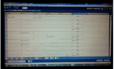
The simulation is in the form of conditioning the operation of the emergency exhaust valve which is carried out with the help of application of the PLC Simulator. Display the ladder diagram for the simulation process is shown in Figure 7.
The simulation process is based on application of the PLC Simulator is shown in Figure 8.
Based-on Figure 8 it is shown that the results of the simulation of the conditioning of the emergency drain valve operation are explained, that:
• The initial level condition in the vessel is empty, so the low alarm level is active;
• When the inlet valve starts to open, the actual level in the vessel is assumed to begin to form;
• The level increment is used by a timer with a time span per second;
• When the level is reached 10 seconds or assuming 10%, the low level alarm starts to reset or disappear;
• Levels continue to rise to 20%, high level alarms and valves start to open to the maximum opening;
• Based on the valve opening, the level drops and the alarm for the high level alarm starts to reset or disappear;
• The valve will close again, if the alarm for low level starts again.
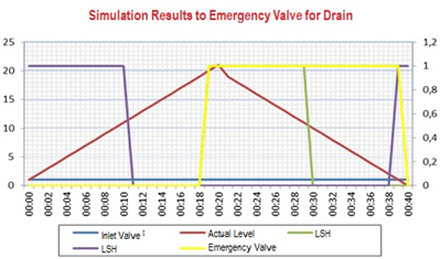
The results of the simulation of the operation of the emergency valve for drain is shown in Figure 9.
Based-on Figure 9 it is shown, that the simulation is carried out on the operation of an emergency drain valve for certainty acquisition, where the valve will open when a signal from the high switch level (LSH) is received and the valve will close again after receiving a signal from the low switch level. Based-on the simulation results obtained, that the valve can operate in accordance with the logic operation. The simulation results can be used as a reference in the implementation of validation tests in actual conditions, when the PLC on the SIS results of the development has been operated.
Figure 7. Display the ladder diagram for the simulation process
Figure 8. The simulation process is based on application of the PLC Simulator
Figure 9. The results of the simulation of the operation of the emergency valve for drain
Based on the results and discussions, conclusions are drawn according to the research objectives. Analysis of SIL-based BPCS, the results obtained in the form of the presence of potential hazards with the indication SIL-2, namely condensate water enters the steam turbine and decreases the pressure value in the purification vessel of the steam. Component specifications are considered for installation of 2 redundant actuators or systems. The overall design of the SIS in the form of a drawing in the form of upgrading (developing) the system of the instrumentation and process control through a block diagram, so that the minimalist function of the SIS as a protection system against personal safety, the environment, and operating facilities. The SIS installed according to development can be achieved a certain minimum level of performance needed for certainty, that the existence of existing protection can be as a protection against all aspects needed. Simulation of the design of the development results in the form of conditioning the operation of the emergency exhaust valve for the acquisition of certainty, that the valve will open when a signal from the Level Switch High (LSH) is received and the valve will be closed again after receiving a signal from the Low Level Switch, so that the valve can operate according to the operation the logic.
To complete the conclusions, it is needed a suggestion in the form of periodic monitoring and evaluation of each the system of instrumentation and process control that has been developed, so that a minimum level of performance can be achieved as a protection against all aspects needed.
|
SIS |
Safety Instrumented Systems |
|
SIL |
Safety Integrity Levels |
|
SIF |
Safety Instrumented Functions |
|
BPCS |
Basic Process Control Systems |
|
IPL |
Independent Protection Layers |
|
FT |
Flow Transmitter |
|
PT |
Pressure Transmitter |
|
BT |
Bourdon Type |
|
LT |
Level Transmitter |
|
LS |
Level Switch |
|
EDV |
Emergency Drain Valve |
|
PS |
Pneumatic Solenoid |
|
PLC |
Programmable Logic Controller |
|
MQ |
Programmable Logic Controller with brand of “MQ” |
|
Rdt. |
Redundant |
|
LSH |
Level Switch High |
|
LSL |
Level Switch Low |
[1] IEC 61511-1 (Edition 2.1 2017-08). (2017). Functional Safety - Safety Instrumented Systems for the Process Industry Sector- Part-1: Framework, definitions, system, hardware and application programming requirements. International Electrotechnical Commission, Geneva, Switzerland.
[2] IEC 61508 (Edition 2.0 2010-08). (2017). Functional Safety of electrical/electronic/programmable electronic safety-related systems Part-1: General Requirement. International Electrotechnical Commission, Geneva, Switzerland.
[3] Klein, M. (2019). The Value of Safety Instrumented Systems. Chemical Engineering Website. https://www.chemengonline.com/value-safety-instrumented-systems/, accessed Jan 20, 2020.
[4] Mitchell, K.J., Herena, P., Longendelpher, T.M., Kuhn, M.C. (2017). Kenexis Safety Instrumented Systems Engineering Handbook. Columbus, OH: Kenexis Consulting Corporation.
[5] Hearn, W.H., Skweres, P., Arnold, A.D., Summers, A.E. (2009). SIF Proof Testing Yields Process Sector Reliability Data. Houston, TX: SIS-TECH Solution.
[6] Generowicz, M. (2016). Functional safety: The next edition of IEC 61511. Proc. of the 6th Safety Control Systems Conference. Melbourne, Australia, pp. 1-11.
[7] Mostia, W.L. (2017). Secure the SIS: Understand the Strength of Your Last Line of Cyber Defense. Control Global Website. https://www.controlglobal.com/articles/2017/secure-the-sis/, accessed on March 17, 2019.
[8] Shiratsu, H. (2018). Comparing Conventional and Sustainable Safety Instrumented Systems. Control Engineering Website. https://www.controleng.com/articles/comparing-conventional-and-sustainable-safety-instrumented-systems/, accessed on Jan. 30, 2019.
[9] Stewart, L. (2019). Back to Basics 04 - Safety Instrumented System (SIS). Exida Website. https://www.exida.com/blog/back-to-basics-04-safety-instrumented-system-sis, accessed on Nov. 21, 2020.
[10] Gruhn, P., Cheddie, H.L. (2006). Safety Instrumented Systems, Design, Analysis, and Justification, 2nd Edition. Durham, NC: ISA (The International Society of Automation).
[11] Mitchell, K.J. (2010). Safety Instrumented Systems Engineering Handbook. Columbus, OH: Kenexis Consulting Corporation.
[12] Barnard, G.S. (2013). Safety Instrumented Systems. Handbook of Loss Prevention Engineering, Volume 1&2, Haight, J.M. (ed.). KGaA, Weinheim (Germany): Wiley-VCH Verlag GmbH & Co.
[13] Gruhn, P., Lucchini, S. (2018). Safety Instrumented Systems: A Life-Cycle Approach. Durham, NC: ISA (The International Society of Automation).
[14] ANSI/ISA Standard S84.01-2004. (2004). Application of Safety Instrumented Systems to the Process Industries, International Society for Measurement & Control. Research Triangle Park, NC.
[15] Summers, A.E. (2007). ANSI/ISA 84.00.01-2004 and Existing Safety Instrumented Systems. Houston, TX: SIS-TECH Solution.
[16] ABB FSM Technical Authority. SIL methodology A methodology for SIL verification in accordance with IEC 61508 and IEC 61511 requirements. Cambridgeshire, UK. https://library.e.abb.com/public/90d6c3e3d73743d6abef08b69990bba1/01_ABB%20SIL%20Methodology%20Brochure.pdf, accessed on June 22, 2020.
[17] C Crossco. Determining Safety Integrity Levels for Your Process Application. Crossco Website. https://www.crossco.com/resources/articles/determining-safety-integrity-levels-for-your-process-application/, accessed on Nov. 23, 2020.
[18] Johnson, C.D. (2014). Process Control Instrumentation Technology, eighth edition. Persons Education Limited, Essex, 1-54.
[19] Richardson, I., Addison, S., Thompson, G. (2013). Steam purity considerations in geothermal power generation. Proc. of the 35th New Zealand Geothermal Workshop. Rotorua, New Zealand, pp. 1-8.
[20] Nkapiani, M.N. (2018). Steam purity challenges in geothermal power plants: A case study of Olkaria IAU. Proceeding of 7th African Rift Geothermal Conference. Kigali, Rwanda, pp. 1-11.
[21] Petrova, T., Dooley, R.B. (2013). Technical guidance document: Steam purity for turbine operation. The International Association for the Properties of Water and Steam. London, United Kingdom.
[22] IDC Technologies Pty Ltd. (2011). Fundamentals of Instrumentation, Process Control, PLCs and SCADA for Plant Operators and Other Non-Instrument Personnel, Revision 5. Perth, Australia.
[23] Industrial Energy Program. (2014). Industrial Steam System Process-Control Scheme: A Best Practice Steam Technical Brief. US Department of Energy.
[24] Industrial Technologies Program (2003). Industrial Heat Pumps for Steam and Fuel Savings: A Best Practices Steam Technical Brief. U.S. Department of Energy, Washington, D.C.