Hiba A. Al-Diraee* | Thair J. Al-Fatlawi
© 2026 The authors. This article is published by IIETA and is licensed under the CC BY 4.0 license (http://creativecommons.org/licenses/by/4.0/).
OPEN ACCESS
In hydraulic engineering, the dissipation of energy at pipe outlets is a significant problem. High velocity flows can cause major damage to infrastructure and erosion downstream in lift stations and gravity sewage networks. This paper provides a comprehensive review of excess kinetic energy control mechanisms and protocols. The emphasis is on the United States Bureau of Reclamation (USBR) Type VI impact basin. The review summarizes the fundamental laws of Turbulent Kinetic Energy (TKE) and turbulent energy dissipation rate. It provides a detailed study of geometrical arrangements like baffle blocks, impact walls, and end sills. In this review, a temporal analysis of the existing literature (1957-2024) is presented to identify the main variables affecting the dissipation efficiency, namely the Froude number, the basin width to inlet depth ratio (W/D) and the vertical pipe offset (d/y1). The results show optimal geometrical changes, such as progressive expansion of the basin and converging angles of the baffles. The review identifies a significant research gap concerning the accurate quantification of hydraulic loads acting on energy dissipator components. The literature review shows that the combination of Computational Fluid Dynamics (CFD) and experimental studies is a promising approach for the improvement of design and optimization of Energy Dissipation Chambers (EDCs).
energy dissipation, USBR Type VI impact basin, lift stations, turbulence modelling, Computational Fluid Dynamics, sewage networks
The velocity of piped flows is higher than that of natural flows. When these flows merge, the higher velocity of the developed flows speeds up the slower-moving watercourse flow, increasing damage [1].
In order to avoid possible damage behind overflow spillways, chutes, sluices, and pipe outlets, the extra kinetic energy must be released either horizontally or vertically, or both. Shear drag, pressure drag, or an increase in piezometric head can all dissipate the energy horizontally. It can dissipate vertically through the upward or downward diffusion of jets.
When designing hydraulic structures, energy dissipation is a frequent issue. Because dissipation mechanisms are so intricate, laboratory experiments utilizing model theory are nearly always required for any suggested design. In order to test any novel energy dissipator design for large structures, model studies are typically economically justified.
Economic considerations do not support such research for small structures, hence, generalized designs have been investigated to address a broader range of circumstances [2].
A common feature in modern sewage networks is the integration of pump-driven flows with gravitational streams. These junctions, often constructed underground, are designated as Energy Dissipation Chambers (EDCs) [3].
Hydraulic structures called stilling basins are used to dissipate the energy of downstream flow, thereby reducing its velocity and energy. Thus, the primary function of stilling basins can be defined as energy dissipation and control. Wastewater with extremely high kinetic energy travels from a pump station to the stilling basin. Wastewater molecules have a lot of potential energy, which the downstream flow transforms into kinetic energy.
Because of the high downstream flow velocity, this kinetic energy is formed; if this energy cannot be diminished or dissipated, it causes damage to the system.
Downstream energy dissipation in hydraulic structures has been considered in many recent studies, and various methods and techniques have been developed to either improve the efficiency of dissipators that are currently on the market or find new dissipators that satisfy the requirements of both high efficiency and low cost. These approaches are divided into five categories:
Although dissipation techniques have been widely used, a more complete understanding of the structural implications and geometric optimization of such systems is still lacking. This article is devoted to lift stations and provides a detailed analysis of the energy dissipation mechanisms at the pipe outputs. It also reviews the academic and practical research to identify the main failure modes in current designs and suggests more reliable approaches to control energy and reduce construction costs.
Extensive research has been conducted on energy dissipation in hydraulic applications such as spillways, culverts, and open-channel structures. This review focuses primarily on energy dissipation at pipe outlets in wastewater lift stations. References to other hydraulic applications are included only for comparative purposes and to highlight design concepts that may be transferred to EDCs in lift stations. This paper discusses the hydraulic behaviour, structural components, and optimisation of outlet stilling basins associated with pumped wastewater systems.
Energy Dissipation: The process of reducing the kinetic or potential energy of the wastewater as it moves through the lifting sewer system. This usually happens at control valves, drop structures or discharge points where energy is converted into turbulence.
Lifting Sewer System (Pump Station): It is a pressurized hydraulic system consisting of mechanical pumping units used to lift wastewater from a lower datum to a higher elevation. This system is significant to overcome topographical limitations and preserve gravity flow in the succeeding segments of the sewage network.
EDCs: Hydraulic devices used in lift stations and sewer systems to reduce excess wastewater energy prior to release into downstream channels. In general, an EDC is equipped with a stilling basin and other hydraulic structures to reduce flow velocity, control turbulence, and minimize erosion and hydraulic damage to downstream infrastructure.
Stilling Basin: A hydraulic structure in an EDC to decrease flow velocity and remove excess kinetic energy by means of turbulence, flow recirculation, and hydraulic interaction with internal components. The main aim is to stabilise the flow downstream of the point at which it enters sewer mains or treatment works.
Energy Dissipation Structures (Appurtenances): Internal hydraulic components situated within a stilling basin or EDC, comprising impact walls, baffle blocks, hanging baffles, hinge walls, and end sills. These components augment turbulence, dissipate surplus flow energy, stabilise the flow, and mitigate erosion, vibration, and structural loading.
Head Loss: The hydraulic energy (in meters or feet of water column) of the wastewater is reduced as the wastewater passes through the lifting system and associated pipelines because of friction, turbulence, or the change in the direction of flow.
The research uses systematic review methodology to assess the current literature on energy dissipation in sewer networks and lift station outlets. To identify a comprehensive list of relevant research, “Google Scholar” and “ResearchGate” were used as primary search engines to access peer-reviewed journals, conference proceedings, and technical book chapters.
The search method was enhanced using precise technical terms and Boolean combinations, including: "Impact dissipater geometry", " EDCs in gravitational sewer systems", "Lift station outlet hydraulics", and "Effect of pipe offset and configuration". The selection was done in order to find papers combining experimental and numerical (Computational Fluid Dynamics (CFD)) methods to get a complete view of the dissipation performance. The extensive screening ensured that high-quality data were included for existing research gaps in structural force measurements and design optimization.
The literature review included publications between 1957 and 2024, which revealed the historical development and current progress in hydraulic energy dissipation research. The initial screening of the retrieved literature was performed using database searches and citation tracking. Duplicate records identified through database searches and citation tracking were removed before the final screening process. Following the relevance assessment, a total of 46 key references were selected for detailed analysis and synthesis. The focus was on peer-reviewed journal articles, conference papers and technical reports that dealt specifically with lift station outlet hydraulics, stilling basins, EDCs, hydraulic performance and structural issues. Studies not related to wastewater lift station applications or lacking sufficient technical information were eliminated from the final review.
Lift stations are used to transport wastewater from lower elevations to higher elevations, especially when the source's height is insufficient for gravity flow and/or when using gravity conveyance would require deep excavation and expensive sewer construction [4].
In order to move wastewater to its destination, a lift station stores a small amount of wastewater and uses pumps to "lift" the wastewater's elevation and pressure. Additionally, lift stations aid in preventing wastewater from returning to the gravity sewers and only flowing ahead.
In order to transport wastewater, often known as sewage, from nearby neighbourhoods to approved wastewater management facilities, lift stations are essential. Private laterals and gravity sewers, which transport wastewater by gravity from each property to a nearby lift station, make up a typical wastewater collecting system.
The effluent is subsequently pumped to a wastewater treatment plant (WWTP) by the lift stations. A collecting system that has no lift stations and solely gravity sewers can be designed.
However, a steady downhill slope is necessary for gravity sewers, and the longer the sewer pipes, the deeper the pipes must be installed. It is possible to gather and transport the flow by gravity using large, deep tunnels. These deep pipes are challenging to maintain and costly to build. Therefore, lift stations are used by engineers to enable wastewater to be transported in shallow pipelines with a reduced diameter. Additionally, lift stations offer the option to route pipes over or around landmarks, rivers, lakes, mountains, valleys, and sensitive natural areas. Since a single pipeline is more cost-effective, several lift stations often pump wastewater into it rather than maintaining separate force mains. As the pipe gathers up the flow from more lift stations, its diameter increases until it reaches its objective, which is frequently the WWTP's headworks.
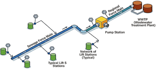
A regional pumping station that receives flow from several lift stations and increases the force main pressure to transport the wastewater to the WWTP may be present in big collection systems. The terms "master pump station" and "booster pump station" are frequently used. Figure 1 depicts an illustration of a lift station network [5].
Figure 1. Schematic representation of a multi-lift station wastewater transport system [4]
5.1 Turbulence characteristics
Generally, flow regimes can be classified into laminar, transitional, and turbulent based on the characteristics of streamlines and stability of the flow field. Turbulent flow is a key element of hydraulic energy dissipation structures because it determines the momentum transfer, the mixing processes, and the energy dissipation mechanisms. In contrast to laminar flow, turbulent flow is characterised by unpredictable fluctuations of velocity, three-dimensional vortex dynamics, and a broad spectrum of eddy sizes. These features increase the momentum and kinetic energy transfer in the flow domain, leading to a higher dissipation of the surplus energy. Turbulence is an important component in the hydraulic efficiency of stilling basins and outlet energy dissipators, since turbulent flows are highly sensitive to boundary conditions and geometrical configurations [6-9].
Figure 2 illustrates the development of laminar, transitional, and turbulent flow regimes over a flat plate, highlighting the transition from orderly to highly turbulent flow conditions.
Figure 2. Development of laminar, transitional, and turbulent flow regimes over a flat plate [6]
5.2 Turbulent Kinetic Energy
Turbulent Kinetic Energy (TKE), denoted by k, is a fundamental parameter used to quantify turbulence intensity within a flow field. It represents the kinetic energy associated with velocity fluctuations and can be calculated from the three fluctuating velocity components in the longitudinal (u′), transverse (v′), and vertical (w′) directions [10]. TKE can then be computed using the following formula:
$k=0.5\left(u^{, 2}+v^{, 2}+w^{, 2}\right)$ (1)
where,
k: TKE.
u′, v′, w′: Velocity fluctuation components in the longitudinal, transverse, and vertical directions, respectively.
The main sources of TKE generation in hydraulic systems are velocity gradients, flow separation, vortex formation, and wake development around hydraulic appurtenances. These mechanisms transfer energy from the mean flow to turbulence, thus increasing the dissipation of energy in the basin [11].
When detailed velocity measurements are unavailable, TKE may be estimated from the turbulence intensity (I) according to:
$k=\frac{3}{2}(U I)^2$ (2)
where,
U: mean flow velocity (m/s).
I: turbulence intensity (dimensionless).
Higher TKE values represent stronger turbulence and mixing, while lower values typically represent a more stable flow [6].
In outlet stilling basins, elevated TKE is commonly generated around impact walls, baffle blocks, and end sills due to flow separation and vortex formation. These turbulent structures promote momentum exchange and enhance hydraulic energy dissipation, while also increasing local hydrodynamic loading on the structural components.
5.3 Turbulent dissipation rate
The energy dissipation in a fluid flow field is mainly caused by two mechanisms, namely, viscous dissipation and turbulent dissipation. Viscous dissipation is due to the inherent viscosity of the fluid, and turbulent dissipation is due to the conversion of TKE from the mean flow kinetic energy (MKE). Turbulent dissipation contributes dominantly to the total energy dissipation in the flow field.
The turbulent dissipation rate, ε, is a measure of the rate of conversion of the TKE of the large- and medium-scale vortices into the kinetic energy of the molecular thermal motion in the smaller-scale vortices. Molecular viscosity assists with this process. The form of epsilon (ε) is obtained from the incompressible Navier-Stokes equation for a time-averaged flow [6]:
$\varepsilon=\frac{\mu}{\rho} \frac{\partial u_i^{\prime}}{x_j} \frac{\partial u_i^{\prime}}{x_j}$ (3)
where,
ε: turbulent dissipation rate (m²/s³).
μ: dynamic viscosity (Pa·s).
ρ: fluid density (kg/m³).
$u_i^{\prime}$: fluctuating velocity component.
xj: spatial coordinate.
Alternatively, the turbulent dissipation rate can be estimated using the TKE (k) and the turbulent intensity scale (l) through the following empirical relationship:
$\varepsilon=C_\mu^{3 / 4} \frac{k^{\frac{3}{2}}}{l}$ (4)
where,
l: turbulence length scale (m).
$C_\mu$: empirical model constant, commonly taken as 0.09.
This formula demonstrates that the magnitude of turbulent dissipation is directly proportional to the intensity of TKE and inversely proportional to the characteristic turbulence scale [6].
Based on extensive research into free turbulent flows, Launder et al. [12] proposed a set of constant values for the $k-\varepsilon$ turbulence model. The constant $C_\mu$, equal to 0.09, is widely used in CFD.
This value is particularly effective for modelling plane jets and mixing layers. While different constants have been traditionally used for simulations involving flows near walls, there is evidence to suggest that the values in this table can also provide reliable results for such cases [13].
The spatial distribution of the turbulent dissipation rate is an important indicator for evaluating the hydraulic performance of EDCs. Regions of high dissipation are typically observed near impact walls, baffle blocks, and end sills, where intense turbulence converts kinetic energy into heat through viscous action, thereby improving energy dissipation efficiency. It should be noted that the turbulent dissipation rate (ε) is a local turbulence parameter and should not be interpreted as hydraulic head loss. Hydraulic head loss represents the overall reduction in flow energy due to friction, turbulence, flow separation, and other dissipative processes, whereas ε specifically quantifies the rate at which TKE is converted into thermal energy through viscous action.
Energy dissipation is critical in minimising excessive flow velocity and the hydrodynamic forces exerted on hydraulic structures. Energy dissipation in outlet stilling basins is mainly due to the generation of turbulence, flow separation, formation of vortices, and momentum exchange, which is facilitated by hydraulic components such as baffle blocks and end sills. The configuration, the shape, and the position of these components have a significant influence on the efficiency of dissipation and on the general hydraulic efficiency of the basin [14].
Multiple studies have shown that alterations in basin shape and internal energy-dissipating features directly influence turbulence characteristics, pressure fluctuations, and the hydrodynamic forces acting on structural components. Thus, optimising basin layouts is crucial for enhancing hydraulic efficiency and structural reliability [15].
Poor geometric arrangements of energy dissipation devices can lead to undesirable flow patterns, higher concentrations of turbulence, or higher structural stresses, but with better flow performance. Therefore, accurate hydraulic design is needed to obtain an optimal compromise between the energy dissipation efficiency and the structural integrity [16].
CFD has been proven to be an important tool for the analysis of flow dynamics in EDCs. CFD simulations give detailed information on velocity distributions, TKE, pressure fields and hydrodynamic loads. This information can be used by engineers to assess and optimise the performance of basins before they are built [17].
Future progress in the CFD methodologies and hydraulic modelling will be reflected in the design of compact, cost-effective, and structurally effective energy dissipation systems for wastewater pumping stations.
Stilling basins dissipate energy through complex configurations of flip buckets, sills, baffles, and other elements. The stilling basins considered are also widely used in practice and have been subjected to various evaluations. They are large and were originally designed for large flows. But they offer a more complete understanding of the different element combinations that could result in effective energy dissipation. In our study, the EDC will be built according to the specifications of impact basin Type VI, as described below.
Why use an impact basin in lift stations:
The wastewater pumped from pumping stations often has increased kinetic energy resulting from the conversion of potential energy into flow velocity. Inadequate dissipation of this excess energy can result in substantial hydraulic disturbances, structural damage, and operational problems in downstream sewer systems and manholes [1].
Accordingly, many energy dissipation methods have been proposed, including EDCs, reverse-flow systems, and inclined energy dissipators. Impact basins with baffle walls are very effective, durable, and suitable for wastewater applications because they have the ability to dissipate large amounts of energy with little construction complexity [1].
The United States Bureau of Reclamation (USBR) Type VI impact basin was developed by the U.S. Bureau of Reclamation and later refined by Bradley and Peterka to provide optimum energy dissipation over relatively short basin lengths and under varying tailwater conditions [18, 19].
The basin consists of a vertical suspended baffle and an end sill, where energy is mainly dissipated by flow impact, vortex formation, turbulence generation, and momentum redistribution [20].
It is advised to operate the Type VI basins at inflow velocities up to 15 m/s and Froude numbers from 1 to 10. Also, the basin can receive open channel inflows and pipe discharges, which makes it suitable for a wide range of hydraulic engineering applications [21].
The Type VI basin is used widely because of several advantages. The suspended baffle is good for producing turbulence and dissipating energy; multiple units can be connected in series to increase discharge capacity, and hydraulic performance is relatively stable for various upstream flow conditions [22].
The configuration and positioning of the baffle wall and associated structural elements greatly influence the hydraulic efficiency of the basin, and extensive experimental and numerical investigations are required.
Impact basins have been used in many studies as EDCs in sewers and wastewater systems. Numerical models for basin design and optimisation, optimal location of EDCs, and hydraulic design standards for pipe outlet applications have been developed in previous studies [3, 23]. Together, these studies show that impact basin research is alive and well and continues to improve the hydraulic and structural effectiveness of energy dissipation structures for lift stations.
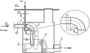
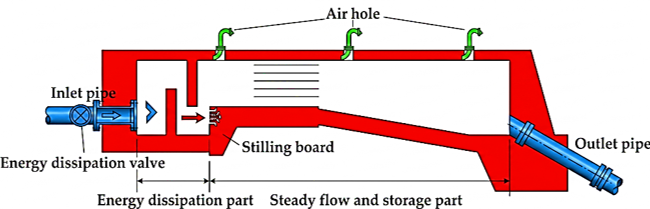
Although the USBR Type VI impact basin provides effective energy dissipation, its application in wastewater lift stations should be evaluated according to site-specific hydraulic and operational conditions. The design process should consider factors such as pipe diameter, solids concentration, potential for corrosion, ventilation requirements, access for maintenance, and inlet flow parameters, which may affect basin performance. Figure 3 illustrates the schematic configuration of an EDC, including its principal hydraulic components used to reduce flow velocity and dissipate excess hydraulic energy in wastewater sewer systems.
Figure 3. Schematic configuration of an energy dissipation chamber (EDC) used to reduce flow velocity and dissipate excess hydraulic energy in sewer systems [3]
One of the major challenges in hydraulic structural design is the effective dissipation of excess flow energy. Downstream of these hydraulic structures, stilling basins are built to disperse the water's excess energy. There are several different kinds of stilling basin designs, including those made by the USBR, Utah State University (USU) energy dissipators, Mahakaal stilling basins, wedge-shaped stilling basins, and manifold stilling basins [24].
Additionally, the size and geometry of these basins influence their performance by creating distinct flow patterns. Chute blocks, baffle blocks, friction blocks, end sills, vertical sills, and splitter blocks are some of the geometrical configurations used in the stilling basin to evenly distribute the turbulence and kinetic energy [18].
There are four ways in which energy dissipation structures can reduce flow energy:
The most important energy dissipation structures that will be used with EDC will be described as follows:
8.1 Impact wall
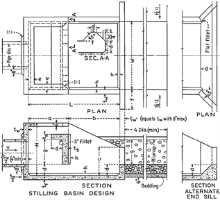
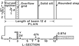
It may be possible to efficiently dissipate surplus energy downstream of hydraulic structures such as overflow spillways, sluices, pipe outlets, etc., by using stilling basins with an impact wall and sill. The impact wall's placement, geometry, and the space between the wall and basin floor determine how it affects flow and/or scour characteristics, as shown in Figure 4.
Figure 4. Geometry and principal components of the United States Bureau of Reclamation (USBR) Type VI impact stilling basin [22]
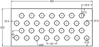
Several studies [19, 22, 26-29] have suggested different types of stilling basins for pipe outlets employing impact walls. The water jet hits the hanging baffle wall or vertical impact wall, distributing the water flow evenly across the channel width. After hitting the hood section of the impact wall, the flow is redirected toward the upper part of the wall and descends onto the stilling basin floor. The hood's dimensions should be such that water splashing is completely eliminated. Additional horizontal shear may result from the baffle wall's bottom gap since a tiny amount of water would pass through it and release more energy [30].
8.2 Standard baffle dissipaters
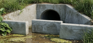
Baffle blocks are generally used to reduce the energy of fast-moving water coming from pipes and culverts. These blocks are simple geometrical shapes that are placed in the flow channel to act as an impact surface, which allows the dissipation of excess energy at the outlet. The West Virginia Division of Highways (WVDOH) has successfully used various baffle-based energy dissipators to control high-velocity flows from roadside culverts [31].
Engineering drawings exist for the current “standard baffle” used by the WVDOH. No information was found on the engineering development process of the “standard” baffle. For a complete discussion of energy dissipators, see the Federal Highway Administration (FHWA) 1983 paper, “Hydraulic Design of Energy Dissipators for Culverts and Channels” (HEC-14) [31].
In the development of new designs of baffle-type dissipators for the WVDOH, three main goals were emphasized:
Simple design: The structures should be easy to conceive and easy to engineer.
Minimum construction cost: The construction cost of the dissipators should be minimum.
Efficient energy dissipation: The new designs should be able to reduce the flow energy efficiently.
Table 1. Design dimensions as a multiple of the culvert diameter for the standard baffle configuration [31]
|
Dimension |
Multiple of Diameter |
|
L |
1.2 |
|
M |
0.6 |
|
N |
1.2 |
|
O |
1.3 |
|
P |
3.9 |
|
Q |
1.8 |
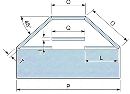
Figure 5. Plan view of the West Virginia Division of Highways (WVDOH) standard baffle dissipator illustrating the arrangement of internal energy dissipation components [31]
In these designs, all dimensions are proportional to the diameter of the culvert except the thickness (T) and the height of the cut-off wall (W). Table 1 provides the dimensions in culvert diameter multiples. The layout of the standard WVDOH baffle dissipator and the arrangement of its internal components are illustrated in Figure 5.
This made it much easier to develop a scale model for hydraulic investigations by using the culvert diameter as a reference for all the dissipator dimensions. This approach was applied equally to all alternative designs to ensure their simplicity and ease of construction. Figure 6 shows a specimen of a conventional baffle dissipater.
Figure 6. Photograph of a baffle-wall energy dissipator illustrating the internal energy dissipation
8.3 Baffle blocks
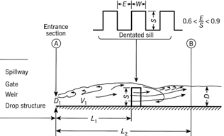
One of the most widely used energy dissipation techniques is baffles. The identical crenelated components that make up baffle blocks are arranged in rows perpendicular to the flow direction. They are frequently positioned close to the jump's toe and operate as impact factors to decrease the depth of the tail water and shorten the stilling basin's length [25]. For instance, baffle blocks have been used in numerous basin designs by HEC-14. Baffle blocks are used in the designs of basins II and III.
Baffles are affected by strong energy flow in three different ways. First, they generate friction, which directly dissipates flow energy. In order to generate shear and release more energy, they secondly reroute the flow into several flow streams. Lastly, they lower the flow's overall velocity, which can cause a hydraulic jump to emerge right away.
Baffle blocks are comparable to sills, with the exception that flow is pushed over and around the blocks. Although they are thought to be superior to sills, they are more costly to build, according to this research [32]. Figure 7 illustrates a standard baffle configuration.
According to geometry, a sloped backside is preferable than a vertical one for the formation of downstream flow, and a vertical front face is ideal [22, 25]. Baffle blocks' sharp front corners aid in energy dissipation. These factors are taken into account when designing the staggered weir in the current study, which resembles two rows of baffle blocks in several aspects. Many designs of baffle blocks were investigated in this research [22].
A flat vertical front face with a sloping back face was the most practical configuration for baffle blocks that could be readily built. Additionally, they evaluated a curved front face with sharp side corners, which worked well for a range of inputs but was more challenging to build. It has been shown that the ideal block height is roughly 1.5 times the inflow depth [33].
Baffle blocks are generally not advised for water velocities more than roughly 20 m/s unless the blocks are specially designed. Otherwise, they may be destroyed by cavitation [33].
Figure 7. Flow pattern over a single row of baffle blocks (dentated sill) used for energy dissipation and flow stabilization [32]
8.4 End sill
Appurtenances are crucial to lowering the energy of flowing water in any stilling basin. Accessories such as an impact wall, splitter block, intermediate sill, end sill, etc., are used in stilling basins for pipe outlets. A terminal component of the stilling basin, the end sill helps to improve the flow pattern downstream of the channel and significantly reduce the energy of flowing water, both of which contribute to the stilling basin's decreased length. The height, shape, and placement of the sill have a significant effect on how much energy the flowing water dissipates. Numerous researchers have employed a variety of end sill designs, including vertical, stepped, dentated solid walls, etc. [22].
In order to serve the additional purpose of diffusing the remaining high-velocity jet that might reach the stilling basin's end, the end sill is often dentate. Additionally, the end sill aids in diverting bottom currents away from the stream bed and upward.
Furthermore, bed material from downstream is brought to the end of the stilling basin by a ground roller that is formed beneath the diverted stream.
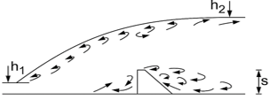
Various types of recommended stilling basin designs for pipe outlets are recommended [27, 34-37]. The end sills utilized in the aforementioned investigations are either semicircular, as described in this research [28]. The energy dissipation was examined in this research [29] by altering the stilling basin's baffle wall gap to shield the downstream structures from severe scouring. The flow behaviour over and around end sill structures, together with their contribution to hydraulic energy dissipation, is illustrated in Figure 8.
Figure 8. Flow behaviour over and around sill structures illustrating their role in hydraulic energy dissipation [25]
8.5 Riprap
For a distance of one basin width downstream from the end sill, riprap is necessary on the channel bottom and side slopes. At the end sill, the riprap on the channel's side slopes needs to reach the height of the basin walls' tops. Riprap must be at least 1/6 of the basin width thick. Under the rock riprap, a layer of bedding or filter material is required, if needed.
The purpose of drawing ES-189 is to make it easier to determine the necessary riprap size. The necessary riprap size must be met or exceeded by at least half of the riprap by weight [31, 38].
There has been a surge in research in recent years in terms of energy dissipation methods in sewage network. Previously, physical simulations, experimental tests and numerical modelling have extensively studied the effects of the dissipater shape, chamber geometry, and the pipe diameter height and shape on energy dissipation. Below is a summary of some studies that have addressed energy dissipation in stilling pools.
9.1 Effect of dissipator shape
The FLOW-3D numerical simulation was employed to optimize stilling basin models [1]. The study's objective was to identify the most effective design by analysing various hydraulic parameters and their impact on flow characteristics. Key variables investigated included the dissipater shapes, their spatial arrangement, the Froude number, and the height of the inlet pipe. The 3D RNG k-ε turbulence model was utilized to evaluate the hydraulic properties, and the results were validated against a case study to select the most suitable stilling basin design. The numerical models and the various dissipater configurations investigated in the FLOW-3D simulations are presented in Figure 9.
Figure 9. Geometrical configurations of the energy dissipation models used in this study: (a) 2-D sketch of the case study; (b) Various dissipaters used in the numerical simulation models [1]
In contrast to Grade's energy appurtenance, more energy-efficient appurtenances for pipe outlets were developed in this research [27] while new designs for stilling basins tailored for deep and narrow outlets were presented in this research [28] These studies investigated the effects of various appurtenances, such as wedge-shaped blocks, weir walls, impact walls, stepped walls, and grids, on the hydraulic performance of the stilling basins. The energy dissipation appurtenances proposed by Goel and Verma are illustrated in Figure 10.
Figure 10. Energy dissipation appurtenances proposed by Goel and Verma for improving stilling basin performance [27]
In order to improve energy dissipation and safeguard downstream buildings from excessive scouring, the baffle wall gap in the stilling basin was examined in this research [29]. In order to evolve the new stilling basin model by altering the gap beneath the wall above the basin, experiments have been conducted with the baffle wall remaining in the same location for different Froude numbers. The performance of outlet basins with baffle walls at the same location but different gaps was assessed using a dimensionless metric known as the performance index (PI), which is the ratio of the scour index to the grain's Froude number. Better basin performance is indicated by higher PI values. It was determined that the effectiveness of the basin is increased by positioning the right baffle wall size in the right location with the right gap [39].
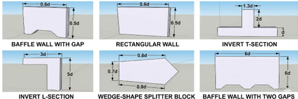
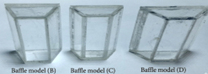
An experimental study was conducted in this research [40] to assess the effect of various baffle block shapes and adverse bed slopes on stilling basin performance. The research tested four baffle block models (A, B, C, and D) across slopes of 0, -0.03, -0.045, and -0.06, for a Froude number range of 3.99 to 7.48. Model D was identified as the most effective and was further tested in single and double-row configurations against Model A. The findings indicate that the use of baffle blocks increased the energy dissipation ratio while decreasing the successive depth ratio, jump length, and roller length. The different baffle block geometries evaluated in the experimental study are shown in Figure 11.
Figure 11. Various baffle block shapes used in the experimental investigation of stilling basin performance [40]
A cellular baffle and many splitters were positioned in the stilling basin during the investigation, and the baffle's positions were altered to evaluate the impact on energy dissipation. To examine the impact of flow rate, velocity was measured at several points in the basin for varying Froude numbers. Several recommendations about the design and efficiency of stilling basins were offered in light of the experiment results [41]. The arrangement of the cellular baffle and flow splitters investigated in the study is illustrated in Figure 12.
Figure 12. Cellular baffle and flow splitter arrangement used to improve energy dissipation efficiency within the stilling basin [41]
9.2 Geometry of energy dissipation room
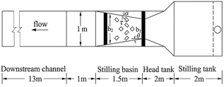
A numerical study was conducted in this research [42] to investigate the effects of the Froude number and the basin width-to-inlet depth ratio (W/D) on the flow characteristics within a USBR VI stilling basin. Using the RNG (k-ε) turbulence model to solve the RANS equations, the study found that increasing the (W/D) ratio from 3.50 to 9.23 significantly improved energy dissipation. Specifically, the average velocity at the basin's end decreased by 80-97%, while the maximum velocity dropped by 40-87%. The turbulent dissipation rate also increased substantially (up to 4.5 times), leading to a fourfold increase in overall turbulent flow energy dissipation. It was suggested that for optimal performance under the tested conditions, the (W/D) ratio should be increased to approximately 10. The geometric configuration of the USBR Type VI stilling basin and the coordinate system used in the numerical simulations are illustrated in Figure 13.
Figure 13. Geometric configuration of the United States Bureau of Reclamation (USBR) Type VI stilling basin and coordinate system adopted for numerical simulations [42]
The hydraulic jump in a USBR II converging stilling basin was numerically evaluated in this research [43] using the FLOW-3D finite volume model. The research validated that FLOW-3D accurately predicts hydraulic jump behaviour, with the flow pattern aligning with the stilling basin’s overall flow profile. Two turbulence models, standard (k-ε) and RNG, were compared against laboratory data. The results showed that the hydraulic jump in a converging basin is superior to that in a parallel-walled basin for all discharges. The RNG turbulence model was found to be the most accurate in predicting hydraulic jump parameters, including air entrainment, velocity, pressure, and Froude numbers [43].
An experimental study was conducted in this research [44] to investigate the effects of baffle blocks and an end sill on an expanding hydraulic jump with an adverse slope. The research aimed to stabilize the flow and improve the hydraulic jump's characteristics. The findings showed that a convergent baffle block design was more effective than a divergent one. A forced diverging basin with an adverse slope significantly reduced both the dimensionless length and subsequent depth of the jump compared to a free diverging basin with a similar slope. The optimal convergence angle for the baffle blocks was found to be 30°, which reduced the hydraulic jump's length and depth ratio by up to 35% and 16%, respectively. It was also noted that placing the baffle blocks at 0.5 Lj of the free diverging basin with an adverse slope effectively modified the hydraulic jump profile [44]. The experimental setup used to investigate the influence of baffle blocks and the end sill is presented in Figure 14.
Figure 14. Experimental setup schematic diagram in (a) plan and (b) side views [44]
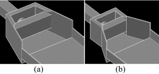
Numerical simulation was used [45] to alter the USBR Type VI stilling basin's geometry. Over a hundred distinct basin designs were developed based on variations in geometric variables. By analysing the outcomes of these designs, it was found that the optimal performance resulted from a basin where the breadth progressively increases after the central wall. The two proposed strategies for gradually expanding the basin width are illustrated in Figure 15 [45].
Figure 15. (a), Gradual expansion of the basin width from the inlet; (b) Gradual expansion of the basin width after the central L-shaped wall [45]
9.3 Effect of the pipe height, shape, and diameter
The effect of inlet pipe height on turbulent energy dissipation within a stilling basin was investigated in this research [1]. Experiments were conducted at Froude numbers of 1.5, 2.5, and 3.5. The results indicate a direct correlation between the ratio of the inlet pipe's diameter to its height above the basin floor (d/y1) and turbulent energy dissipation. Specifically, as the )d/y1( ratio increased from 0.14 to 0.25, the turbulent energy dissipation also increased. The positions of the dissipators were kept constant to isolate the effect of the inlet pipe height.
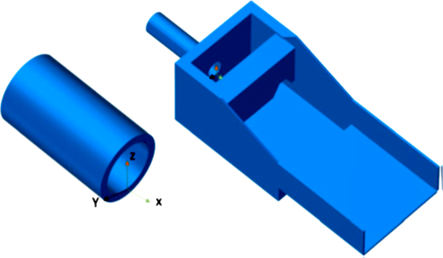
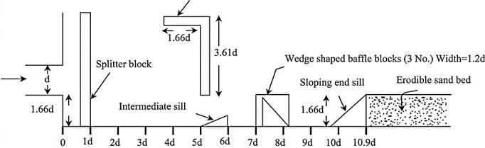
New, shorter, and more effective designs than the USBR Type VI stilling basin models were suggested in this research [26] based on laboratory experiments. The models are evaluated on a 4 cm by 4 cm square hole (d = 4 cm) with a diverging side wall at a slope of 1 V: 0.8 H and a Froude number (Fr) = 6.83. Splitter blocks, impact walls, baffle blocks, intermediate sills, and end sills are among the various sized and shaped accessories that are evaluated in the lab at various sites. It was found that a row of wedge-shaped blocks helps to disperse the water jet over a shorter basin length with diverging side walls, thereby improving energy dissipation. In comparison to the USBR impact Type VI stilling basin model, it was discovered that the stilling basin models' length may be decreased by more than 15%, from 12.9 d to 10.9 d. The experimental model used to evaluate the hydraulic performance of the modified stilling basin configurations is presented in Figure 16.
Figure 16. Experimental model used to evaluate the hydraulic performance of modified stilling basin configurations [26]
9.4 Energy Dissipation Box in gravitational sewer systems
The Energy Dissipation Box (EDB) was investigated in this research [23] as a novel pressure-reducing method. A direct relationship between its location and pressure head amplitude was established by deriving a theoretical equation for its ideal placement. Numerical simulations showed that the needed box volume and pressure head oscillations are greatly reduced when the box is positioned at its theoretically ideal location rather than upstream. The results show that, as long as the water level oscillations inside the box stay constant, this ideal location offers better hydraulic performance.
A methodology for optimizing EDB placement was introduced in this research [46] based on overcurrent capacity and the sum-of-the-maximum hydrostatic pressure head (SMHPH). Through numerical simulations and the derivation of an "extreme location equation," the study showed that putting the EDB closer to the downstream pipe greatly reduces pressure gradient oscillations. Additionally, it was discovered that decreasing the box's cross-sectional size under high beginning water depths improves its protective impact and lowers the overall EDB volume. The study emphasizes that overcurrent capacity and SMHPH are essential factors for EDB placement and design. The structural configuration of a typical EDB used in gravity sewer systems is illustrated in Figure 17.
It has been shown in previous studies that many hydraulic and geometrical characteristics have a great effect on the performance of energy dissipators. These are dissipator configuration, stilling basin geometry, inlet pipe specifications, and design of EDB. The most relevant experimental and numerical studies are summarised in this section, as shown in Table 2.
Figure 17. Structural configuration of a typical Energy Dissipation Box (EDB) used in gravity sewer systems [46]
Table 2. Summary of previous studies on energy dissipation systems in sewer networks and lift stations
|
Ref. |
Structure / Study |
Method |
Parameter |
Main Finding |
|
[1] |
USBR VI basin |
CFD |
Shape, Fr, pipe height |
Optimized energy dissipation |
|
[23] |
EDB |
Numerical |
Box location |
Reduced pressure oscillation |
|
[26] |
Modified basin |
Experimental |
Basin layout |
Shorter basin length |
|
[27] |
Pipe outlet basin |
Experimental |
Appurtenances |
Improved hydraulic performance |
|
[28] |
Deep outlet basin |
Experimental |
Basin geometry |
Better energy dissipation |
|
[29] |
Baffle wall |
Experimental |
Wall gap |
Higher performance index |
|
[40] |
Baffle blocks |
Experimental |
Block shape |
Highest dissipation with Model D |
|
[41] |
Cellular baffle |
Experimental |
Baffle position |
Improved flow dissipation |
|
[42] |
USBR VI basin |
CFD |
W/D ratio |
Higher turbulent dissipation |
|
[43] |
Converging basin |
CFD |
Basin geometry |
Better hydraulic jump |
|
[44] |
Diverging basin |
Experimental |
Baffle angle |
Best performance at 30° |
|
[45] |
USBR VI basin |
CFD |
Geometry |
Optimum gradual expansion |
|
[46] |
EDB |
Numerical |
Optimum location |
Reduced box volume |
Note: CFD: Computational Fluid Dynamics; EDB: Energy Dissipation Basin; USBR: United States Bureau of Reclamation; PI: Performance Index.
Table 2 gives a summary of the most important experimental and numerical studies on energy dissipation systems in sewer networks and lift stations. The analysed studies show that the design of the dissipater structure, the arrangement of baffles, the basin size, the inlet pipe characteristics and the EDB configuration are of great importance for the hydraulic performance and the energy dissipation efficiency. Nevertheless, further studies are necessary to improve EDCs and to evaluate the hydraulic loads for different working conditions.
The literature on lift stations and energy dissipation systems has been surveyed, and significant progress has been achieved in understanding the principal features of fluid flow and turbulence. However, theoretical fluid dynamics and practical engineering applications for the development of sustainable and efficient lifting stations still differ widely. These research gaps need to be identified to develop integrated design standards taking into account structural integrity and hydraulic complexity.
This is a summary of the main research gaps identified in the above synthesis:
The physical processes of turbulence and dissipation rates of energy are well understood; however, little work has been done to relate these hydraulic features to the direct mechanical response of baffle blocks. Understanding the conversion of stochastic velocity fluctuations into dynamic thrust pressures impacting the long-term structural integrity of the dissipators is a key aspect.
Most of the design criteria used today come either from hydraulic models for large structures or from traditional gravity systems. The discrepancy is due to the lack of studies on the efficiency of hydraulic baffles in the confined space of lift stations, especially in high-velocity flow conditions above 6 m/s. Such conditions are complex hydraulic situations that require innovative technical solutions.
Although individual components such as impact walls or sills have been studied in isolation, there is a lack of research on the synergistic interaction among hydraulic components within the EDC. The “optimal design” of sewage networks with different physical properties to balance the dissipation efficiency and reduced footprint remains an uncharted research gap that calls for further theoretical and experimental exploration.
There is an urgent need for research applying a dual-validation approach that simultaneously incorporates load measurements and velocity profiles with CFD simulations. It is important to combine these in order to bring theory and practice together so that the statistics can be accurately produced and used to make decisions regarding the construction or renovation of lift stations.
This review presents a comprehensive synthesis of the literature on energy dissipation mechanisms and structures in high-velocity wastewater systems. The primary challenge identified is the efficient and safe dissipation of the high kinetic energy associated with piped flows to prevent downstream damage.
Although such traditional methods, such as the free hydraulic leap, are effective, their large structural length makes them unsuitable for small-scale applications. This constraint of space and economy has developed into more compact and effective alternatives.
The reviewed literature demonstrates that energy dissipation in wastewater systems, particularly at lift stations, remains a major hydraulic engineering challenge because excessive flow velocities can lead to erosion, vibration, structural damage, and operational problems. Among the available energy dissipation methods, USBR Type VI impact basins have proven to be one of the most effective solutions due to their compact design and their ability to dissipate energy without requiring deep tailwater conditions. In addition, EDBs and chambers have been successfully applied in gravity sewer systems to reduce pressure fluctuations and improve hydraulic performance when installed at their optimum locations.
The reviewed studies also indicate that internal hydraulic appurtenances, including impact walls, baffle blocks, splitter blocks, and end sills, play an important role in enhancing energy dissipation efficiency and reducing the required basin length. Furthermore, the hydraulic performance of these structures is strongly influenced by several geometric and hydraulic parameters, such as the Froude number, basin width-to-depth ratio, inlet pipe characteristics, and the arrangement of internal dissipating elements. Recent advances in CFD, particularly FLOW-3D and turbulence-based numerical models, have provided effective tools for evaluating and optimizing the design of energy dissipation systems. Overall, the reviewed studies confirm the importance of adopting an integrated hydraulic and engineering design approach to develop more compact, efficient, and reliable energy dissipation systems for wastewater applications.
Future research should focus on developing more compact and efficient energy dissipators through the integration of advanced CFD techniques, experimental validation, and innovative hydraulic configurations to enhance system performance and ensure long-term structural reliability in wastewater applications.
Conflict of interest: The authors declare that they have no known competing financial interests or personal relationships that could have appeared to influence the work reported in this paper.
Data availability statement: No new experimental or numerical datasets were generated for this review. All information analyzed in this study is available within the cited references.
Author contributions (CRediT):
Conceptualization: Hiba Ali Al-Diraee and Thair Jabbar Mizhir Al-Fatlawi.
Methodology: Hiba Ali Al-Diraee.
Literature Review: Hiba Ali Al-Diraee.
Writing-Original Draft Preparation: Hiba Ali Al-Diraee.
Writing-Review & Editing: Thair Jabbar Mizhir Al-Fatlawi.
Supervision: Thair Jabbar Mizhir Al-Fatlawi.
All authors have read and approved the final version of the manuscript.
Statement on the use of Generative Artificial Intelligence: Generative Artificial Intelligence (GenAI) was used solely for language refinement, grammar checking, formatting assistance, and manuscript organization. All scientific content, literature selection, interpretation, critical analysis, and conclusions were independently developed, verified, and approved by the authors.
[1] Mohammed, S.R., Nile, B.K., Hassan, W.H. (2020). Modelling stilling basins for sewage networks. In IOP Conference Series: Materials Science and Engineering, 3rd International Conference on Engineering Sciences Kerbala, Iraq, 671(1): 012111. https://doi.org/10.1088/1757-899X/671/1/012111
[2] Flammer, G.H., Skogerboe, G.V., Wei, C.Y., Rasheed, H. (1970). Closed conduit to open channel USU stilling basin. Report No. 482. https://digitalcommons.usu.edu/water_rep/482.
[3] Stolbikhin, I., Semenov, A. (2020). Simulation studies of numerical relationship of sewage energy dissipation chamber efficiency. Journal of Physics: Conference Series, 1614(1): 012017. https://doi.org/10.1088/1742-6596/1614/1/012017
[4] Spellman, F.R. (2013). Handbook of Water and Wastewater Treatment Plant Operations. CRC Press, p. 923. https://doi.org/10.1201/b15579
[5] [5] Ludwigson, M.N. (2021). Lift station design (Course 401). PDH Academy. https://pdhacademy.com/wp-content/uploads/2023/06/401-Lift-Station-Design.pdf.
[6] [6] Pope, S.B. (2000). Turbulent Flows. Cambridge University Press, Cambridge, UK. https://doi.org/10.1017/CBO9780511840531
[7] Koziol, A.P. (2011). Turbulent kinetic energy of water in a compound channel. Annals of Warsaw University of Life Sciences-SGGW, Land Reclamation, 43(2): 194-205. https://doi.org/10.2478/v10060-011-0055-z
[8] Wiggins, S. (2003). Introduction to Applied Nonlinear Dynamical Systems and Chaos. Springer, New York. https://link.springer.com/book/10.1007/b97481?page=2#toc.
[9] Alhamdi, S.F.H. (2018). Intermittency effects on the universality of local dissipation scales in turbulent boundary layer flows with and without free-stream turbulence. Doctor of Philosophy Dissertation, University of Kentucky, Lexington, Kentucky, USA. https://uknowledge.uky.edu/me_etds/116.
[10] Nakagawa, H., Nezu, L. (2017). Turbulence in Open Channel Flows. CRC Press, p. 294. https://www.routledge.com/Turbulence-in-Open-Channel-Flows/Nakagawa-Nezu/p/book/9789054101185.
[11] Koziol, A., Urbanski, J., Kiczko, A., Krukowski, M., Siwicki, P. (2016). Turbulent intensity and scales of turbulence after hydraulic jump in rectangular channel. Annals of Warsaw University of Life Sciences-SGGW, Land Reclamation, 48(2). https://doi.org/10.1515/sggw-2016-0008
[12] Launder, B.E., Morse, A., Rodi, W., Spalding, D.B. (1973). Prediction of free shear flows: A comparison of the performance of six turbulence models. NASA Langley Research Centre, Free Turbulent Shear Flows, 1: 361-426. https://ntrs.nasa.gov/api/citations/19730019433/downloads/19730019433.pdf.
[13] Launder, B.E., Spalding, D.B. (1983). Paper 8-the numerical computation of turbulent flows. In Numerical Prediction of Flow, Heat Transfer, Turbulence and Combustion. Pergamon, pp. 96-116. https://doi.org/10.1016/B978-0-08-030937-8.50016-7
[14] Macián-Pérez, J.F., García-Bartual, R., Huber, B., Bayon, A., Vallés-Morán, F.J. (2020). Analysis of the flow in a typified USBR II stilling basin through a numerical and physical modelling approach. Water, 12(1): 227. https://doi.org/10.3390/w12010227
[15] Zaffar, M.W., Hassan, I. (2023). Hydraulic investigation of stilling basins of the barrage before and after remodelling using FLOW-3D. Water Supply, 23(2): 796-820. https://doi.org/10.2166/ws.2023.032
[16] Ye, Y.C., Peng, L.M., Yang, W.C., Zou, Y., Cao, C.Y. (2020). Calculation of friction force for slurry pipe jacking considering soil-slurry-pipe interaction. Advances in Civil Engineering, 2020: 6594306. https://doi.org/10.1155/2020/6594306
[17] Ghosh, A., Gupta, P., Singh, R.K. (2021). Metaheuristic optimization framework for drag reduction using bioinspired surface riblets. arXiv preprint, arXiv:2109.09650. https://doi.org/10.48550/arXiv.2109.09650
[18] Peterka, A.J. (1964). Hydraulic design of stilling basins and energy dissipators. Bureau of Reclamation, United States Department of the Interior, Bureau of Reclamation, Denver, Colorado, USA, pp. 1-222.
[19] Tiwari, H.L., Gahlot, V.K., Goel, A. (2010). Stilling basins below outlet works-an overview. International Journal of Engineering Science and Technology, 2(11): 6380-6385. https://idc-online.com/technical_references/pdfs/civil_engineering/STILLING%20BASINS.pdf.
[20] Khan, L.A. (2011). Computational fluid dynamics modeling of emergency overflows through an energy dissipation structure of a water treatment plant. In World Environmental and Water Resources Congress 2011: Bearing Knowledge for Sustainability, pp. 1484-1493. https://doi.org/10.1061/41173(414)155
[21] Salmasi, F., Abraham, J. (2024). New Perspectives on the Design of Stilling Basins. In Theory and Applications of Engineering Research, 6: 56-107. https://doi.org/10.9734/bpi/taer/v6/8608A
[22] Bradley, J.N., Peterka, A.J. (1957). Hydraulic design of stilling basins: Short stilling basins for canal structures, small outlet works, and small spillways (Basin III). Journal of the Hydraulics Division, 83(5): 1403-1-1403-24. https://doi.org/10.1061/JYCEAJ.0000125
[23] Ni, W.X., Zhang, J., Chen, S. (2021). Optimal location of energy dissipation box in long-distance and high-drop gravitational water supply system. Water, 13(4): 461. https://doi.org/10.3390/w13040461
[24] Tiwari, H.L., Goel, A., Suresh, S., Tiwari, S. (2015). Effect of inverted T-shape splitter blocks on the performance of stilling basin models. Aquatic Procedia, 4: 1561-1568. https://doi.org/10.1016/j.aqpro.2015.02.202
[25] Hager, W.H., Li, D. (1992). Sill-controlled energy dissipator. Journal of Hydraulic Research, 30(2): 165-181. https://doi.org/10.1080/00221689209498932
[26] Goel, A.R.U.N. (2007). Experimental study on stilling basins for square outlets. In Third WSEAS International Conference on Applied and Theoretical Mechanics, Spain, pp. 14-16.
[27] Goel, A., Verma, D.V.S. (2001). Model studies on stilling basins for pipe outlets. Irrigation and Drainage Systems, 15(1): 81-91. https://doi.org/10.1023/A:1017989028411
[28] Verma, D.V.S., Goel, A. (2003). Development of efficient stilling basins for pipe outlets. Journal of Irrigation and Drainage Engineering, 129(3): 194-200. https://doi.org/10.1061/(ASCE)0733-9437(2003)129:3(194)
[29] Tiwari, H.L. (2013). Analysis of baffle wall gap in the design of stilling basin model. International Journal of Civil Engineering and Technology, 4(4): 66-71.
[30] Tiwari, H.L., Goel, A. (2016). Effect of impact wall on energy dissipation in stilling basin. KSCE Journal of Civil Engineering, 20(1): 463-467. https://doi.org/10.1007/s12205-015-0292-5
[31] Corry, M.L. (1983). Hydraulic design of energy dissipators for culverts and channels. Hydraulic Engineering Circular No. 14. Federal Highway Administration, U.S. Department of Transportation, Washington, DC, USA.
[32] Zhang, C. (2023). Energy dissipation optimization for circular culverts. Master's Thesis, University of Nebraska-Lincoln, Lincoln, NE, USA. https://digitalcommons.unl.edu/civilengdiss/199/.
[33] Chanson, H. (2015). Energy Dissipation in Hydraulic Structures. CRC Press, p. 178. https://doi.org/10.1201/b18441
[34] Verma, D.V.S., Goel, A., Rai, V. (2004). New stilling basins designs for deep rectangular outlets. IJE Transactions A: Basics, 17(1): 1-10.
[35] Ali, A.M., Mohamed, Y.A. (2010). Effect of stilling basin shape on the hydraulic characteristics of the flow downstream radial gates. Alexandria Engineering Journal, 49(4): 393-400. https://doi.org/10.1016/j.aej.2010.08.001
[36] Abbaspour, A., Dalir, A.H., Farsadizadeh, D., Sadraddini, A.A. (2009). Effect of sinusoidal corrugated bed on hydraulic jump characteristics. Journal of Hydro-environment Research, 3(2): 109-117. https://doi.org/10.1016/j.jher.2009.05.003
[37] Al-Fatlawi, T.J.M., Al-Mansori, N.J.H., Othman, N.Y. (2020). Laboratory study of stilling basin using trapezoidal bed elements. Scientific Review Engineering and Environmental Sciences, 29(4): 409-420. https://doi.org/10.22630/PNIKS.2020.29.4.35
[38] Buchanan, K., Clarke, C., Voyde, E. (2013). Hydraulic energy management: Inlet and outlet design for treatment devices. Auckland Council, Auckland, New Zealand.
[39] Tiwari, H. (2013). Design of stilling basin model with impact wall and end sill. Research Journal of Recent Sciences, 2(3): 59-63. https://www.isca.me/rjrs/archive/v2/i3/10.ISCA-RJRS-2012-422.pdf.
[40] Abbas, A., Alwash, H., Mahmood, A. (2018). Effect of baffle block configurations on characteristics of hydraulic jump in adverse stilling basins. In MATEC Web of Conferences, 162: 03005. https://doi.org/10.1051/matecconf/201816203005
[41] Sobhan Aleyasin, S., Fathi, N., Vorobieff, P. (2015). Experimental study of the type VI stilling basin performance. Journal of Fluids Engineering, 137(3): 034503. https://doi.org/10.1115/1.4029164
[42] Behnamtalab, E., Maskani, V., Sarkardeh, H. (2023). Numerical study of turbulent flow in USBR VI stilling basin. Applied Water Science, 13(7): 146. https://doi.org/10.1007/s13201-023-01956-9
[43] Babaali, H., Shamsai, A., Vosoughifar, H. (2015). Computational modelling of the hydraulic jump in the stilling basin with convergence walls using CFD codes. Arabian Journal for Science and Engineering, 40(2): 381-395. https://doi.org/10.1007/s13369-014-1466-z
[44] Eshkou, Z., Dehghani, A.A., Ahmadi, A. (2018). Forced hydraulic jump in a diverging stilling basin using angled baffle blocks. Journal of Irrigation and Drainage Engineering, 144(8): 06018004. https://doi.org/10.1061/(ASCE)IR.1943-4774.0001328
[45] Behnamtalab, E., Ghodsian, M., Zarrati, A., Salehi Neyshabouri, S.A.A. (2019). Geometry modification of USBR type VI stilling basin using numerical simulation. Journal of Hydraulics, 13(4): 1-15. https://doi.org/10.30482/jhyd.2019.82704
[46] Ni, W.X., Hu, Y.N., Li, Z.H. (2024). A theoretical derivation and comparison method for the optimal location for energy dissipation boxes. Water, 16(15): 2189. https://doi.org/10.3390/w16152189