Ronald Onofre Cayllahua | Jhair Tito Medina | Juan Valdez Loaiza | José Canazas Rodríguez* | Christofer Diaz Arapa
© 2026 The authors. This article is published by IIETA and is licensed under the CC BY 4.0 license (http://creativecommons.org/licenses/by/4.0/).
OPEN ACCESS
Efficient cooling of high-power electric motors is critical in industrial applications such as ball mills, where continuous thermal loads accelerate stator insulation degradation. This study numerically evaluates the thermohydraulic performance of two water jacket designs applied to a 2250 kW induction motor, considering the combined effects of Reynolds number and hexagonal boron nitride (h-BN) nanofluid concentration. A three-dimensional computational fluid dynamics (CFD) model based on the SST k–ω turbulence model was developed, incorporating temperature-dependent properties for an ethylene glycol–water mixture (60:40 by volume) and h-BN nanofluids up to 3 vol.%. The results show that increasing the Reynolds number enhances convective heat transfer in both configurations. However, the second geometry provides a more uniform flow distribution, reducing the maximum coolant temperature by 3–4 ℃ and the outlet temperature by up to 0.6 ℃, while also decreasing the pressure drop by 8–14%. The addition of h-BN further improves thermal performance, achieving outlet temperature reductions of up to 4.5% at 3 vol.% with moderate increases in pressure drop. These findings indicate that the combination of optimized channel geometry and dielectric nanofluids is an effective strategy to improve the thermal reliability and operational performance of high-power industrial motors.
nanofluids, hexagonal boron nitride, water jacket, electric motors, computational fluid dynamics
Electric motors are the primary driving components of ball mills used in mining, cement production, and metallurgical industries. These machines operate under sustained heavy loads and harsh environmental conditions, where high ambient temperatures and mechanical vibrations are common [1, 2]. In such applications, motor reliability directly determines plant productivity, energy efficiency, and maintenance costs. As industry moves toward higher power density and improved energy efficiency, modern electric motors are required to deliver greater torque within more compact volumes, which significantly intensifies thermal management challenges [3, 4]. During operation, electromagnetic and mechanical losses in the stator windings, rotor bars, and bearings are converted into heat [5-7]. If this heat is not effectively dissipated, elevated temperatures accelerate insulation degradation, increase winding resistance, and intensify copper losses, creating a self-reinforcing overheating cycle that drastically reduces service life [6, 8]. In continuous-duty applications such as ball mills, where motors operate near rated load for extended periods, efficient cooling is therefore essential to ensure safe operation and long-term reliability.
To control temperature rise, several cooling strategies have been developed for high-power electric machines, including forced air systems, oil circulation, and liquid-based cooling [5, 9, 10]. Among these, water jacket cooling has emerged as one of the most effective solutions for large induction and synchronous motors due to its high heat transfer capacity and compact integration around the stator housing [11-13]. Compared with air cooling, water jackets provide significantly higher convective heat transfer coefficients and improved temperature control under fluctuating operating conditions. In recent years, numerical and experimental studies have focused on enhancing motor cooling performance through optimized jacket geometries, improved flow distribution, and multi-channel configurations aimed at reducing thermal gradients and hot spots [14, 15]. In parallel, nanofluids—defined as suspensions of nanoparticles in base fluids such as water or ethylene glycol—have been extensively investigated as advanced coolants [16]. Studies involving Al₂O₃-, CuO-, and ZnO-based nanofluids report improved thermal conductivity and reduced operating temperatures, although often at the expense of increased viscosity and pressure drop [17, 18].
Nanofluids have attracted increasing attention in electric motor cooling applications over the past decade. Both experimental and numerical studies report enhanced convective heat transfer in cooling jackets and compact heat exchangers. Deriszadeh and de Monte [19] numerically analyzed laminar nanofluid flow in spiral channels using three-dimensional computational fluid dynamics (CFD) simulations, showing that higher nanoparticle concentrations improve heat transfer but also increase pressure drop and pumping power. In a subsequent study [20], the same authors evaluated an Al₂O₃–water nanofluid in a spiral jacket using finite element analysis, highlighting the trade-off between thermal enhancement and hydraulic penalties. Keuter et al. [21] investigated a direct-liquid-cooled motor, highlighting the strong influence of coolant velocity and winding temperature on system efficiency and thermal management. Jayakumar and Sreekanth [22] conducted CFD simulations using different nanofluids and reported operating temperatures up to 30% lower than those obtained with pure water. Kulkarni et al. [23] experimentally investigated Al₂O₃ nanofluids in diesel generator jackets, observing improved heat exchanger performance despite a slight reduction in cogeneration efficiency. Additional studies have reported similar trends in generators and induction motors, confirming the potential of nanofluids to enhance thermal management, albeit with moderate increases in pumping power requirements [24-26].
Despite these advances, important limitations remain. Many studies focus on simplified channel geometries or laboratory-scale systems that do not fully represent the complex spiral water jacket configurations used in multi-megawatt industrial motors, such as those employed in ball mills. In addition, most investigations consider metallic nanoparticles, which may introduce electrical conductivity risks in high-voltage environments. Unlike conventional metallic nanoparticles such as Al₂O₃ and CuO, hexagonal boron nitride (h-BN) combines high thermal conductivity with excellent electrical insulation, making it particularly attractive for electric motor cooling applications where dielectric safety is required. Previous studies have demonstrated that h-BN nanofluids can provide significant thermal enhancement while maintaining electrical insulation properties, which is a critical advantage in high-power electrical equipment [17, 24, 26-28]. However, its performance in realistic three-dimensional water jacket geometries remains insufficiently explored. Furthermore, most CFD studies on electric motor cooling focus on generic spiral or straight-channel water jackets, with limited attention to how different flow path arrangements influence thermal uniformity and hydraulic losses in large industrial motors. In practical applications, cooling channel design must simultaneously improve heat removal, reduce pressure drop, and ensure uniform temperature distribution around the stator. Therefore, evaluating alternative channel configurations is essential for developing scalable cooling solutions for multi-megawatt motor systems.
The present study addresses these gaps by numerically investigating two water jacket configurations representative of industrial cooling layouts used in a high-power electric motor. The first configuration employs a predominantly circumferential flow path, whereas the second adopts a multi-pass arrangement designed to promote more uniform coolant distribution and lower hydraulic resistance. A three-dimensional CFD model is developed to evaluate the combined effects of Reynolds number and h-BN nanoparticle concentration, incorporating temperature- and concentration-dependent thermophysical correlations for the nanofluid. By systematically comparing geometric configurations and coolant compositions under realistic industrial heat flux conditions, this work aims to quantify the actual thermal enhancement achievable with dielectric nanofluids while assessing the associated hydraulic penalties. The results provide practical guidance for improving the thermal reliability, efficiency, and operational stability of high-power electric motors in mining and heavy industrial applications. In mining and metal-processing facilities, electric motors are commonly exposed to continuous-duty operation, high thermal loads, and harsh environmental conditions, making cooling reliability a critical design requirement. Under these conditions, cooling systems must ensure effective heat removal while minimizing hydraulic losses and maintenance demands. The proposed water jacket configurations contribute to these objectives by improving thermal uniformity and cooling performance, supporting more reliable and energy-efficient operation of high-power industrial equipment.
This section describes the numerical framework developed to evaluate the heat transfer performance of a water-jacketed cooling system in an electric motor of a ball mill, using h-BN nanofluids. The methodology involves geometric modeling of the cooling jacket, formulation of equations governing fluid flow and heat transfer, incorporation of the thermophysical properties of the nanofluids, and execution of computational simulations with convergence verification.
2.1 Electric motor description
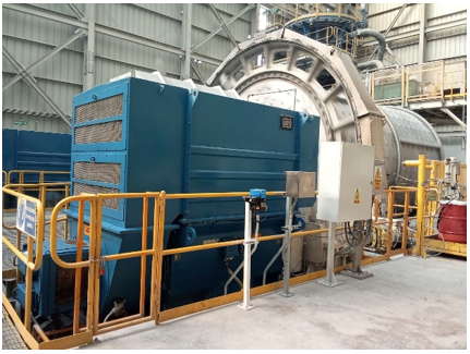
This study considers a three-phase induction motor, typically used to drive industrial ball mills, characterized by continuous operation and high torque demands. The following analysis considers a high-power 2250 kW motor, as shown in Figure 1. The cooling system consists of a water jacket integrated around the stator frame, designed to provide uniform temperature distribution while minimizing thermal hot spots. The coolant enters the jacket through an inlet manifold, circulates through channels surrounding the stator, and exits through an outlet at either the opposite or the same end, depending on the designer.
Figure 1. A 2250 kW electric motor driving a ball mill in a concentrator plant
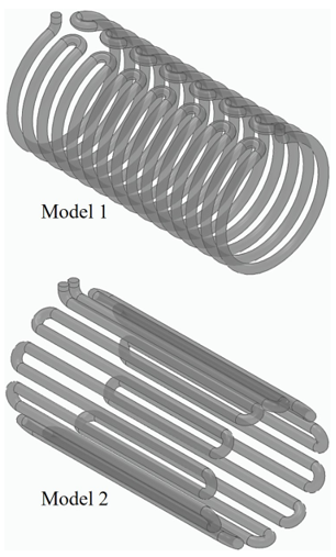
During continuous operation, a fraction of the supplied electrical power is transformed into thermal losses, primarily associated with electromagnetic and resistive phenomena in the stator. For a 2250 kW industrial motor with a typical efficiency of 97%, total losses are around 70 kW, of which approximately 35% correspond to thermal losses generated in the stator. Considering only the external cylindrical surface of the core—defined by a diameter of 1.26 m and an axial length of 2.9 m—an effective lateral area of 11.48 m² is obtained for heat dissipation to the water jacket. We applied an approximate heat flux of 2100 W/m² to simulate typical industrial thermal loads. This value adequately represents the typical thermal load in high-power motors used in ball mill drives, thus providing a consistent basis for evaluating the performance of the water jacket cooling system under realistic industrial conditions. Figure 2 shows the isometric drawings of the two water jacket models proposed for the present study. The proposed water jacket geometries are based on cooling channel configurations commonly employed in heavy-duty industrial electric motors, including marine and large-drive applications. For comparative purposes, both models were defined with the same overall length but different numbers of tube-side passes, allowing the influence of internal flow arrangement to be isolated in this initial evaluation.
Figure 2. Isometric view of the proposed water jacket models
Table 1 shows the geometric parameters of the models proposed. The cooling channels were modeled as circular ducts distributed around the external surface of the stator frame, forming a multi-pass water jacket configuration. In Model 1, the channel follows a predominantly circumferential path around the stator with 15 passes, producing a more tortuous flow path. In contrast, Model 2 consists of 22 passes arranged in a more longitudinal configuration, which allows a smoother flow progression along the motor casing. The channels maintain a constant circular cross-section with a diameter of 0.1 m along the entire flow path. Both configurations were designed to cover the external cylindrical surface of the stator, ensuring uniform thermal interaction between the cooling fluid and the motor housing. The two configurations were selected to evaluate the influence of flow path arrangement on thermohydraulic performance. Model 1 represents a more conventional circumferential layout commonly used in industrial cooling jackets, while Model 2 was designed to improve flow distribution along the stator length and reduce local hydraulic losses. This comparison enables assessment of potential benefits in terms of thermal uniformity, pressure drop reduction, and scalability for high-power motor applications.
Table 1. Geometric parameters of the proposed model
|
Parameter |
Value |
|
Channel Length (m) |
67 |
|
Channel Diameter (m) |
0.1 |
|
Number of passes |
Model 1: 15 Circumferential Model 2: 22 Horizontal |
|
Cross-sectional area (m²) |
0.00785 |
|
Total heat transfer area (m²) |
21.05 |
|
Stator outer diameter (m) |
1.26 |
|
Stator axial length (m) |
2.9 |
|
Channel pitch (m) |
Model 1: 0.26 Model 2: 0.18 |
|
Channel configuration |
Model 1: Spiral Model 2: Multi-pass |
|
Flow direction |
Circumferential progression along the stator |
2.2 Governing equations and thermophysical properties of the fluids
The flow of the coolant and nanofluids within the water jacket is assumed to be steady, incompressible, and turbulent. The standard SST k–ω turbulence model is applied to explain the typical turbulent behavior of liquid cooling circuits in industrial engines. The governing equations are derived from the conservation of mass, momentum, and energy, expressed as:
$\frac{\partial u}{\partial x}+\frac{\partial v}{\partial y}+\frac{\partial w}{\partial z}=0$ (1)
$\begin{gathered}\rho\left(u \frac{\partial u}{\partial x}+v \frac{\partial u}{\partial y}+w \frac{\partial u}{\partial z}\right)=-\frac{\partial p}{\partial x}+\mu\left(\frac{\partial^2 u}{\partial x^2}+\frac{\partial^2 u}{\partial y^2}+\frac{\partial^2 u}{\partial z^2}\right)\end{gathered}$ (2)
$\begin{gathered}\rho\left(u \frac{\partial v}{\partial x}+v \frac{\partial v}{\partial y}+w \frac{\partial v}{\partial z}\right)=-\frac{\partial p}{\partial y}+\mu\left(\frac{\partial^2 v}{\partial x^2}+\frac{\partial^2 v}{\partial y^2}+\frac{\partial^2 v}{\partial z^2}\right)\end{gathered}$ (3)
$\begin{gathered}\rho\left(u \frac{\partial w}{\partial x}+v \frac{\partial w}{\partial y}+w \frac{\partial w}{\partial z}\right)=-\frac{\partial p}{\partial z}+\mu\left(\frac{\partial^2 w}{\partial x^2}+\frac{\partial^2 w}{\partial y^2}+\frac{\partial^2 w}{\partial z^2}\right)\end{gathered}$ (4)
$\rho c\left(u \frac{\partial T}{\partial x}+v \frac{\partial T}{\partial y}+w \frac{\partial T}{\partial z}\right)=k\left(\frac{\partial^2 T}{\partial x^2}+\frac{\partial^2 T}{\partial y^2}+\frac{\partial^2 T}{\partial z^2}\right)$ (5)
The numerical model is therefore formulated directly from the fundamental conservation equations of mass, momentum, and energy for incompressible turbulent flow. These equations are discretized using the finite volume method and solved iteratively to obtain the coupled velocity, pressure, and temperature fields within the cooling channel domain. This physics-based formulation ensures that the predicted thermohydraulic behavior arises from first principles rather than empirical curve fitting.
The base fluid is a mixture of ethylene glycol and water in a 60:40 ratio (by volume), a common coolant in high-power industrial engines. The thermophysical properties of the nanofluid are dependent on temperature and concentration through empirical correlations shown in Table 2 [29].
In the correlations presented in Table 2, the temperature T is expressed in ℃. Density is obtained in kg·m⁻³, specific heat in J·kg⁻¹·K⁻¹, thermal conductivity in W·m⁻¹·K⁻¹, and dynamic viscosity in Pa·s. These correlations are valid within the temperature range specified in Table 2.
Table 2. Correlation of ethylene glycol/water (60:40 by volume) properties for 20 ℃ < T < 80 ℃ [29]
|
Property |
Correlation |
R2 |
|
Density |
$\rho=-0.002434 T^2+1.021793 T+969.249964$ |
0.99 |
|
Specific heat |
$c=0.003354 T+2.4854$ |
0.99 |
|
Thermal conductivity |
$k=-0.000004236 T^2+0.003297 T-0.198222$ |
0.99 |
|
Viscosity |
$\mu=0.000000511 T^2-0.000364 T+0.065613$ |
0.99 |
The following correlations have been used to predict nanofluid density and specific heat, respectively, at different temperatures and concentrations [30].
$\rho_{n f}=\phi \rho_{n p}+(1-\phi) \rho_{b f}$ (6)
$(\rho c)_{n f}=\phi(\rho c)_{n p}+(1-\phi)(\rho c)_{b f}$ (7)
Michael et al. [31] developed correlations for the thermal conductivity and viscosity of ethylene glycol and water with h-BN nanosheets.
$k_{n f}=0.35271+\left(0.0438 * T^{0.1871}\right) \phi^{0.2230}$ (8)
$\mu_{n f}=5.538+\phi^{0.34905}-T^{0.39116}$ (9)
In this study, three different volume concentrations (1%, 2%, and 3%) of h-BN nanosheets suspended in the base fluid were considered. The density and specific heat of this material were also considered, based on previous studies, as 2270 kg/m³ [32] and 1015 J·kg⁻¹·K⁻¹ [33].
The thermophysical property correlations adopted in this study were selected based on their experimental validation for ethylene glycol–water mixtures reported in the ASHRAE Handbook [29]. These correlations are applicable within the temperature range of 20–80 ℃ and are widely used for brine-type coolant mixtures. The correlations proposed by Michael et al. [31] were experimentally validated for h-BN nanofluids with volume fractions up to 3% and temperatures between 20 ℃ and 60 ℃, which encompasses the operating conditions considered in the present simulations. The correlations for density and specific heat follow classical effective medium approximations widely applied for dilute nanofluids, where particle agglomeration effects are minimal. These models are considered appropriate and physically consistent for predicting thermophysical behavior under the investigated conditions.
Although the thermophysical properties are evaluated using experimentally validated correlations, their incorporation into the conservation equations preserves the mathematical consistency of the model, as transport phenomena are governed by the resolved velocity and temperature gradients within the computational domain. The nanoparticle concentration was limited to 3 vol.% because higher concentrations may substantially increase viscosity and pressure losses while potentially affecting long-term suspension stability and sedimentation behavior. These aspects were not considered in the present study and require future experimental investigation under industrial operating conditions [28, 31].
2.3 Numerical simulation and convergence analysis
All simulations were performed using ANSYS Fluent. A hybrid finite volume mesh with hexahedral elements was used, with local refinement in the curved regions to capture their effects. The SIMPLE algorithm was used for pressure-velocity coupling, and second-order windward schemes were applied to the momentum and energy equations to improve accuracy. Convergence criteria were set at 10⁻³ for continuity and momentum residuals, and 10⁻⁶ for energy. Mesh independence was verified by comparing the outlet temperature and pressure drop between successive mesh refinements; variations of less than 1% were considered acceptable, as shown in Table 3. In addition to the mesh independence analysis, standard mesh quality metrics were evaluated to ensure numerical accuracy. The maximum skewness remained below 0.75, the minimum orthogonal quality exceeded 0.5, and the aspect ratio was maintained below 10 within acceptable limits for CFD simulations. Based on this comparison, 500,000 elements were identified as the most suitable number. Details of the simulation input data are given in Table 4.
Table 3. Evaluation of the mesh independence of the 2 geometry models
|
Model |
Elements |
Outlet Temp. (K) |
Difference (%) |
Pressure Drop (Pa) |
Difference (%) |
|
Model 1 |
101707 |
317.57584 |
- |
221.50993 |
- |
|
201135 |
317.58165 |
0.001830 |
217.09714 |
2.032634 |
|
|
300086 |
317.58239 |
0.000233 |
215.31919 |
0.825727 |
|
|
400097 |
317.58212 |
0.000085 |
213.53275 |
0.836613 |
|
|
500267 |
317.58206 |
0.000019 |
212.45465 |
0.507451 |
|
|
600278 |
317.58201 |
0.000016 |
211.57501 |
0.415762 |
|
|
Model 2 |
115458 |
317.89811 |
- |
234.83197 |
- |
|
200658 |
317.81973 |
0.024659 |
221.09410 |
6.213584 |
|
|
302250 |
317.78171 |
0.011964 |
209.14964 |
5.710961 |
|
|
400320 |
317.73242 |
0.015513 |
204.17150 |
2.438217 |
|
|
500514 |
317.69964 |
0.010318 |
202.86494 |
0.644056 |
|
|
600591 |
317.66603 |
0.010590 |
201.74330 |
0.555972 |
Table 4. Description of the boundary conditions and numerical parameters
|
Boundary Condition |
Description |
|
Flow Regime |
Steady, incompressible, turbulent |
|
Turbulence model |
SST k–ω |
|
Wall condition |
No-slip |
|
Inlet |
Fully developed velocity profile obtained for steady-state condition Temperature: 300 K |
|
Outlet |
Outflow |
|
Uniform heat flux from stator surface |
2100 W/m2 (Described in section 2.1) |
|
External jacket walls |
Adiabatic |
The numerical model was developed under the following assumptions: steady-state, three-dimensional, incompressible flow of a Newtonian fluid; homogeneous single-phase approach for the nanofluid; no-slip boundary condition at solid walls; negligible buoyancy effects; and temperature-dependent thermophysical properties evaluated using the empirical correlations described in Table 2. Turbulence effects were modeled using the SST k–ω model. These assumptions are consistent with typical forced-convection analyses in industrial cooling channels. The SST k–ω turbulence model was selected because it provides improved accuracy in near-wall regions while maintaining robust performance in the core flow domain. This characteristic is particularly important for water-jacket cooling channels, where heat transfer is strongly influenced by boundary layer development and local flow separation. Although the model has been extensively validated for internal turbulent flows, the present simulations assume steady-state conditions and a homogeneous single-phase nanofluid approach. At higher Reynolds numbers, additional turbulence structures and transient flow phenomena may affect local temperature and pressure predictions, introducing uncertainty not captured by the current model.
At the inlet, a velocity inlet boundary condition was imposed. The inlet velocity was calculated from the specified Reynolds number using the hydraulic diameter of the channel and the thermophysical properties of the coolant. The inlet temperature was fixed at 300 K, representing typical operating conditions for industrial motor cooling systems. Turbulence intensity was assumed to be 5%, which is commonly used for internal turbulent flows in engineering applications.
At the outlet, an outflow boundary condition was applied, assuming that the flow is fully developed and that the diffusion fluxes of all variables in the flow direction are negligible. This condition is appropriate for internal forced convection problems where the outlet location is sufficiently far from the inlet region.
The simulation matrix included variations in coolant velocity corresponding to Reynolds numbers between 4500 and 8500, encompassing typical operating conditions for industrial water-jacketed refrigeration. The input velocity condition in the software was imposed considering this range of Reynolds numbers, the fluid density, and the hydraulic diameter of the duct. It is important to mention that only two parameters vary: the Reynolds number and, in parallel, the density with the addition of nanoparticles. The outlet temperature and resulting pressure drops were analyzed to evaluate the influence of h-BN nanofluid concentration on the overall thermohydraulic performance of the system. The flow regime and heat transfer characteristics are interpreted within a dimensionless framework, primarily through the Reynolds number, enabling comparison with classical internal flow theory and established correlations for turbulent convection.
In addition to the mesh independence analysis, numerical uncertainty was controlled by monitoring residual convergence below 10-³ for continuity and momentum equations and 10-6 for the energy equation and ensuring stabilization of integral quantities such as outlet temperature and pressure drop. While the finite volume discretization introduces inherent numerical diffusion and truncation error, the selected mesh density and convergence criteria were verified to limit discretization effects to within negligible variation between successive mesh refinements for key output parameters. It is acknowledged that additional uncertainty may arise from turbulence modeling assumptions and thermophysical property correlations; however, these models were selected within their validated operating ranges, minimizing extrapolation error.
This section presents a detailed analysis of the thermal and hydrodynamic behavior of the two water jacket designs evaluated, considering variations in Reynolds number (Re = 4500–8500) and in the concentration of h-BN nanoparticles (0–3 vol.%). The effects on temperature distribution, outlet temperature, static pressure, and pressure drop are quantitatively described in order to identify the most efficient configuration for industrial applications in high-power motors. In this study, the static pressure field refers to the local distribution of static pressure throughout the cooling channel, whereas the pressure drop is defined as the difference between the area-averaged static pressure at the inlet and that at the outlet.
3.1 Influence of Reynolds number and geometry
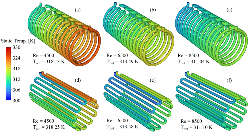
Figure 3 shows the three-dimensional coolant temperature distribution for both water jacket designs at Reynolds numbers of 4500, 6500, and 8500. An increase in Reynolds number enhances convective heat transfer, leading to a general reduction in fluid temperature. However, the magnitude of this effect strongly depends on the channel geometry. In Model 1, the tortuous channel layout promotes the formation of low-velocity and recirculation regions that act as localized heat accumulation zones, reducing the effective convective heat transfer. Regions of low velocity associated with recirculation may act as thermal stagnation zones, increasing local thermal resistance and promoting hotspot formation. This behavior is particularly evident at the lowest flow condition, where extended high-temperature regions are observed along the stator surface. Although these regions decrease in size and intensity as the flow rate increases, they persist due to the inherent geometric complexity of the channel. The presence of such localized heating may increase the risk of hotspot formation under continuous high-load operation. In contrast, Model 2 exhibits a more uniform temperature distribution across all flow conditions. Its more linear channel configuration promotes a smoother flow path, reducing recirculation zones and enhancing flow stability. A clear thermal advantage over Model 1 is observed even at low flow conditions, and this difference becomes more pronounced as turbulence intensifies. At the highest Reynolds number, Model 2 achieves peak temperatures 3–4 ℃ lower than those of Model 1 under identical boundary conditions, corresponding to an overall improvement of approximately 12–15% in convective performance.
Figure 3. Temperature distribution along the tube (a) Model 1 Re = 4500, (b) Model 1 Re = 6500, (c) Model 1 Re = 8500, (d) Model 2 Re = 4500, (e) Model 2 Re = 6500, (f) Model 2 Re = 8500
The observed thermal behavior can also be interpreted in terms of turbulence distribution within the flow domain. The flow regime (Re = 4500–8500) corresponds to fully developed turbulent conditions, where turbulent mixing plays a key role in enhancing convective heat transfer. In this context, Model 2 is expected to promote a more uniform distribution of turbulent structures along the channel due to its smoother geometry, which reduces flow separation and recirculation intensity. This more homogeneous flow behavior enhances fluid mixing and thermal energy transport from the heated wall to the bulk fluid, resulting in lower peak temperatures.
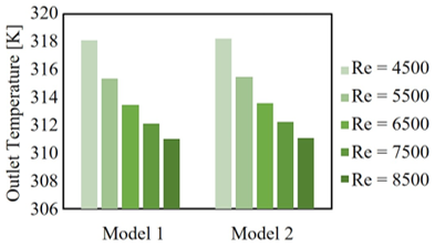
Figure 4 further illustrates these differences through the average outlet temperature. Model 1 shows a reduction of approximately 2.0–2.8 ℃ as the Reynolds number increases from 4500 to 8500, while Model 2 achieves a decrease between 2.5 and 3.5 ℃ over the same range. Although these differences may appear moderate, for thermal loads on the order of 20–30 kW at the stator surface, they represent a significant increase in heat removal per cycle, resulting in a lower thermal load on the motor insulation system. These results highlight that geometric optimization can yield thermal improvements comparable to those obtained by increasing flow rate, but without a proportional rise in pumping power.
Figure 4. Outlet temperature at different Reynolds numbers from 4500 to 8500 for the two proposed models
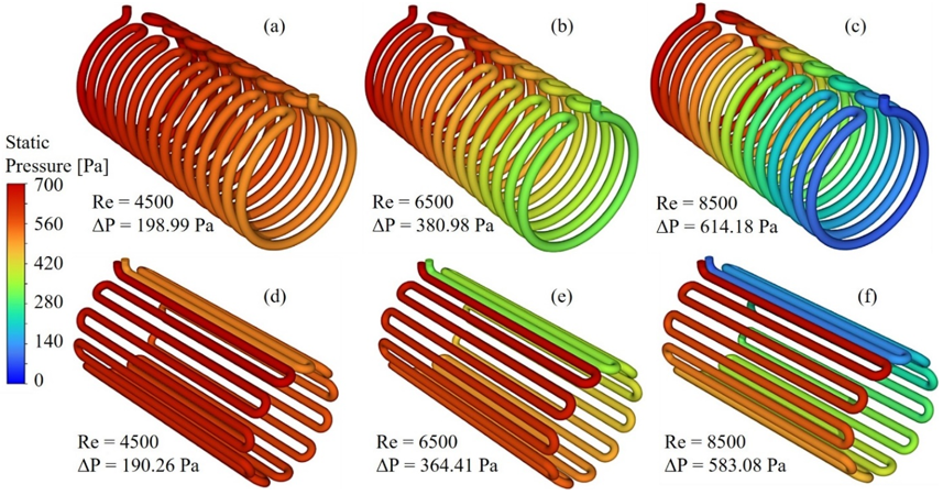
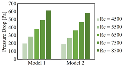
The hydraulic behavior is presented in Figures 5 and 6. Model 1 exhibits higher pressure losses due to secondary flow effects associated with channel curvature, flow separation, and local contractions. As a result, it shows consistently higher pressure drops across the entire Reynolds number range. At the highest flow condition, the pressure drop is up to 14% greater than that of Model 2. This increase directly translates into higher pumping power requirements, typically in the range of 5–10% based on standard industrial correlations. By contrast, Model 2 maintains a more uniform pressure distribution and significantly lower overall pressure losses, making it a more energy-efficient configuration. The reduced frictional effects also contribute to lower mechanical stress on the pumping system, which may extend equipment lifetime and reduce operational costs.
Overall, the results demonstrate that channel geometry has a comparable—and in some aspects greater—impact on thermal performance than increasing Reynolds number. While higher flow rates enhance heat transfer, the geometric design governs flow uniformity and the formation of thermal gradients. For high-power industrial applications, such as multi-megawatt ball mill motors, Model 2 represents a more efficient and reliable cooling solution due to its improved thermal uniformity and reduced hydraulic penalties. The improved thermal uniformity observed in Model 2 reduces the formation of localized hot spots, which are commonly associated with accelerated insulation aging in continuous-duty electric motors. The reduction of approximately 3–4 ℃ in peak coolant temperature may contribute to improved thermal reliability and longer service life. Furthermore, the results suggest that channel arrangement can be used as a practical design parameter for customizing cooling jackets in large-scale industrial motors according to specific thermal and hydraulic requirements.
Figure 5. Static pressure distribution along the tube (a) Model 1 Re = 4500, (b) Model 1 Re = 6500, (c) Model 1 Re = 8500, (d) Model 2 Re = 4500, (e) Model 2 Re = 6500, (f) Model 2 Re = 8500
Figure 6. Pressure drop at different Reynolds numbers from 4500 to 8500 for the two proposed models
In addition to lower outlet temperatures, thermal performance was evaluated through the reduction of peak coolant temperatures and the mitigation of localized hot spots. The observed decrease of approximately 3–4 ℃ in maximum temperature indicates improved thermal uniformity throughout the cooling jacket. Furthermore, the pressure drop trends presented as a function of Reynolds number provide a practical assessment of the hydraulic requirements associated with each configuration.
3.2 Influence of nanoparticle concentration
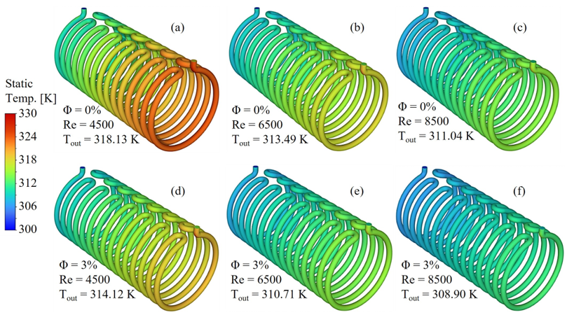
Figure 7 shows the effect of nanoparticle concentration on the temperature distribution for extreme cases (0 and 3 vol.%) under the evaluated flow conditions. The use of h-BN nanofluid leads to a consistent reduction in fluid temperature compared to the base fluid, primarily due to its higher effective thermal conductivity and the resulting attenuation of thermal gradients. Under low flow conditions, the base fluid exhibits extended high-temperature regions, whereas the 3 vol.% nanofluid reduces the maximum temperature by approximately 2.1–2.8 ℃. This thermal improvement becomes more pronounced as flow intensity increases, reaching values of 3–3.5 ℃ under intermediate conditions and exceeding 4 ℃ at the highest flow regime, corresponding to an overall enhancement of 6–8% relative to the base fluid.
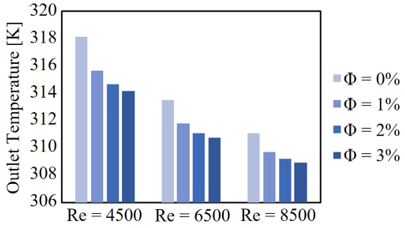
Figure 8 presents the variation of outlet temperature as a function of nanoparticle concentration for the three Reynolds numbers considered. A monotonic and nearly linear decrease is observed as the h-BN volume fraction increases, indicating that the enhancement in effective thermal conductivity directly translates into improved heat extraction. Within the investigated range (0–3 vol.%), the outlet temperature reduction reaches up to 4.5%, demonstrating that nanoparticle concentration is an effective parameter for thermal optimization without introducing nonlinear effects or flow instabilities.
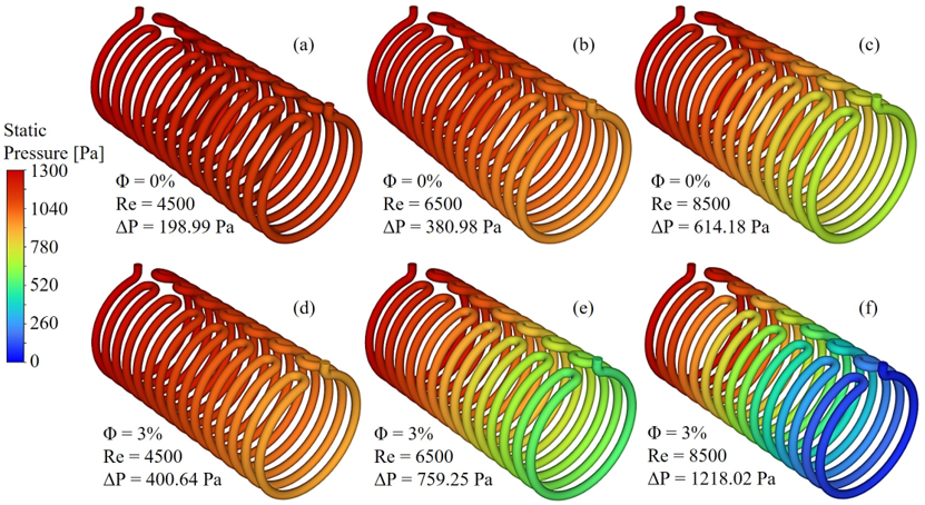
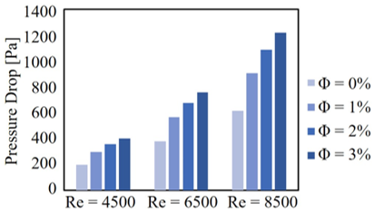
The hydraulic response is shown in Figures 9 and 10. Increasing nanoparticle concentration results in a moderate rise in pressure gradients and total pressure drop due to the corresponding increase in effective viscosity. However, even at 3 vol.%, the additional hydraulic penalty remains within acceptable operational limits. This indicates that the improvement in thermal performance is not accompanied by a disproportionate increase in pumping power requirements, preserving the hydraulic stability of the system.
Overall, the results demonstrate that h-BN nanofluids enhance heat transfer while maintaining stable hydraulic behavior. For high-power motors operating under continuous load, the additional temperature reduction contributes to extending stator lifespan and increasing the operational safety margin. Compared to studies using metallic nanoparticles such as Al₂O₃ or CuO, where typical outlet temperature reductions range from 1–3%, the present results show comparable or improved performance at similar concentrations. An additional advantage of h-BN is its dielectric nature, which eliminates the risk of electrical conduction near the windings—a critical requirement in high-power applications.
Figure 7. Temperature distribution along the tube (a) ϕ = 0% Re = 4500, (b) ϕ = 0% Re = 6500, (c) ϕ = 0% Re = 8500, (d) ϕ = 3% Re = 4500, (e) ϕ = 3% Re = 6500, (f) ϕ = 3% Re = 8500
Figure 8. Outlet temperature at different nanofluid concentrations for three Reynolds numbers
Figure 9. Static pressure distribution along the tube (a) ϕ = 0% Re = 4500, (b) ϕ = 0% Re = 6500, (c) ϕ = 0% Re = 8500, (d) ϕ = 3% Re = 4500, (e) ϕ = 3% Re = 6500, (f) ϕ = 3% Re = 8500
Figure 10. Pressure drop at different nanofluid concentrations for three Reynolds numbers
These findings have direct implications for the thermal management of high-power electric motors used in ball mills and other heavy-duty industrial systems. The combined reduction in outlet temperature and thermal gradients contributes to lower stator operating temperatures. Considering that insulation lifespan may decrease by approximately 50% for every 10 ℃ increase in temperature, even moderate reductions of 3–5 ℃ can significantly extend service life and reduce maintenance requirements. In addition, the lower pressure drop associated with optimized channel geometry further improves system efficiency and reliability. Therefore, the combined use of optimized geometry and dielectric nanofluids represents a practical strategy for enhancing thermal performance and operational durability in industrial motor cooling systems. The results also reveal a clear thermohydraulic trade-off between heat transfer enhancement and hydraulic resistance. Increasing Reynolds number and h-BN concentration improves heat removal but also leads to higher pressure losses. Nevertheless, the optimized channel arrangement of Model 2 mitigates part of this hydraulic penalty by maintaining lower pressure drops while achieving superior thermal performance. This interaction between geometry and nanofluid concentration suggests that cooling system optimization should consider both thermal effectiveness and hydraulic requirements to achieve efficient industrial operation.
Although h-BN nanofluids demonstrated favorable thermohydraulic performance under the investigated conditions, long-term operational aspects such as nanoparticle sedimentation, material aging, and stability under fluctuating flow conditions were not considered in the present study. In industrial environments, additional factors including mechanical vibrations, humidity, and extended operating periods may influence nanofluid durability and thermal performance. Therefore, future experimental studies should evaluate the long-term stability and reliability of h-BN nanofluids under representative industrial operating conditions.
To further assess the reliability of the numerical model, the obtained results were compared with trends reported in previous studies on liquid-cooled electric motors and nanofluid-based cooling systems. Experimental and numerical works using nanofluids such as Al₂O₃ and CuO [22-26] report temperature reductions and heat transfer enhancements of similar order of magnitude, particularly at moderate nanoparticle concentrations. The outlet temperature reductions observed in the present study, reaching up to 4.5% at 3 vol.%, are consistent with these findings. In addition, the increase in pressure drop with both Reynolds number and nanoparticle concentration follows the expected behavior for turbulent internal flows and agrees with trends widely reported in the literature. These results are also consistent with classical correlations for forced convection in ducts, where higher flow velocities enhance heat transfer while increasing friction losses. Overall, the model reproduces the expected physical behavior of the system, providing confidence in the validity and robustness of the numerical approach.
Although experimental validation was beyond the scope of the present study, the predicted temperature reductions and pressure-drop trends are consistent with previously reported numerical and experimental investigations of liquid-cooled electric motors and nanofluid-based cooling systems [22-26]. From an engineering perspective, reducing operating temperatures contributes to improved insulation reliability and thermal management objectives commonly addressed in industrial motor design standards and best-practice guidelines [5, 9, 11].
Also, although a quantitative techno-economic analysis was not performed in this study, the proposed cooling strategies can be qualitatively assessed in terms of operational efficiency. The reduction in operating temperature and pressure drop observed in Model 2 and h-BN nanofluid configurations suggests potential indirect economic benefits through lower pumping power demand and improved thermal reliability. In industrial motor systems, reduced operating temperatures are strongly associated with extended insulation lifespan and decreased maintenance frequency, which can significantly reduce lifecycle costs. Future work should include a detailed techno-economic evaluation and standardized scalability testing to support industrial implementation and comparison with conventional cooling systems.
This study evaluated the thermohydraulic performance of two water jacket configurations for high-power electric motor cooling using CFD simulations. The results demonstrate that channel geometry plays a critical role in determining both thermal and hydraulic performance. Model 2 provided a more uniform flow distribution, reduced recirculation zones, and achieved lower peak and outlet temperatures, while also exhibiting a significantly lower pressure drop compared to Model 1. The use of h-BN nanofluids further enhanced heat transfer performance, producing outlet temperature reductions of up to 4.5% at 3 vol.% concentration with only moderate increases in pressure drop. This indicates that nanoparticle concentration can be effectively used as a thermal optimization parameter without compromising hydraulic stability. From an engineering perspective, the results indicate that optimizing coolant channel arrangement is an effective strategy for improving the thermohydraulic performance of industrial motor cooling systems. Model 2 is particularly suitable for high-power industrial motors operating under continuous-duty conditions, such as mining ball mills, large conveyor drives, and power generation equipment, due to its improved thermal uniformity and lower pressure losses. Compared with conventional water-jacket cooling layouts reported in the literature [14, 21, 25], the proposed configuration may contribute to improved equipment reliability, reduced maintenance requirements, and extended insulation service life. Although both configurations are technically feasible, Model 1 may be considered where manufacturing or installation constraints limit channel redesign. Future work should include experimental validation and long-term assessment of nanofluid stability under industrial operating conditions. Overall, the combination of optimized channel geometry and dielectric nanofluids represents an effective strategy for improving thermal management, reducing energy consumption, and enhancing the operational reliability of high-power industrial motors.
|
c |
specific heat, J‧kg-1‧K-1 |
|
k |
thermal conductivity, W‧m-1‧K-1 |
|
T |
temperature, K |
|
P |
pressure, Pa |
|
u, v, w |
velocity components along the x, y and z directions, respectively, m‧s-1 |
|
x, y, z |
cartesian coordinates along the surface and normal to it, respectively |
|
Greek symbols |
|
|
ρ |
density, kg‧m-3 |
|
μ |
dynamic viscosity, Pa‧s |
|
ϕ |
volume fraction, % |
|
Subscripts |
|
|
bf |
base fluid |
|
nf |
nanofluid |
|
np |
nanoparticles |
[1] Odeyar, P., Apel, D.B., Hall, R., Zon, B., Skrzypkowski, K. (2022). A review of reliability and fault analysis methods for heavy equipment and their components used in mining. Energies, 15(17): 6263. https://doi.org/10.3390/en15176263
[2] Bortnowski, P., Gładysiewicz, L., Król, R., Ozdoba, M. (2021). Energy efficiency analysis of copper ore ball mill drive systems. Energies, 14(6): 1786. https://doi.org/10.3390/en14061786
[3] Li, X., Sun, T., Huang, S., Liang, J. (2023). Review and perspectives on thermal management methods for permanent magnet synchronous motors. Journal of Electrical Engineering (China), 18(4): 20-34. https://doi.org/10.11985/2023.04.003
[4] Rosli, N.S., Ibrahim, R., Ismail, I., Omar, M. (2022). Modeling of high voltage induction motor cooling system using linear regression mathematical models. PLOS ONE, 17(11): e0276142. https://doi.org/10.1371/journal.pone.0276142
[5] Zou, Z., Liu, S., Kang, J. (2024). Degradation mechanism and online electrical monitoring techniques of stator winding insulation in inverter-fed machines: A review. World Electric Vehicle Journal, 15(10): 444. https://doi.org/10.3390/wevj15100444
[6] Denkena, B., Bergmann, B., Klemme, H. (2020). Cooling of motor spindles—A review. The International Journal of Advanced Manufacturing Technology, 110(11-12): 3273-3294. https://doi.org/10.1007/s00170-020-06069-0
[7] Ma, J., Xue, Y., Han, Q., Li, X., Yu, C. (2022). Motor bearing damage induced by bearing current: A review. Machines, 10(12): 1167. https://doi.org/10.3390/machines10121167
[8] Soltani, M., Nuzzo, S., Barater, D., Franceschini, G. (2022). Investigation of the temperature effects on copper losses in hairpin windings. Machines, 10(8): 715. https://doi.org/10.3390/machines10080715
[9] Konovalov, D., Tolstorebrov, I., Eikevik, T.M., Kobalava, H., Radchenko, M., Hafner, A., Radchenko, A. (2023). Recent developments in cooling systems and cooling management for electric motors. Energies, 16(19): 7006. https://doi.org/10.3390/en16197006
[10] Tikadar, A., Johnston, D., Kumar, N., Joshi, Y., Kumar, S. (2021). Comparison of electro-thermal performance of advanced cooling techniques for electric vehicle motors. Applied Thermal Engineering, 183: 116182. https://doi.org/10.1016/j.applthermaleng.2020.116182
[11] Wang, Q., Wu, Y., Niu, S., Zhao, X. (2022). Advances in thermal management technologies of electrical machines. Energies, 15(9): 3249. https://doi.org/10.3390/en15093249
[12] Tang, Y., Sun, S., Yu, W., Hua, W. (2023). Thermal analysis of water-cooling permanent magnet synchronous machine for port traction electric vehicle. Electronics, 12(3): 734. https://doi.org/10.3390/electronics12030734
[13] Xu, Y., Duan, X., Xu, M., Han, A., Yu, W. (2025). Research on dual-waterway cooling system of high-power-density permanent magnet synchronous machine. PLOS ONE, 20(9): e0332155. https://doi.org/10.1371/journal.pone.0332155
[14] Jeon, K., Park, M., Park, J., Choi, H., Lee, K.D., Lee, J.J., Kim, C.W. (2023). Analysis of cooling characteristics of permanent magnet synchronous motor with different water jacket design using electromagnetic–thermal fluid coupled analysis and design of experiment. Machines, 11(9): 903. https://doi.org/10.3390/machines11090903
[15] König, P., Sharma, D., Konda, K.R., Xie, T., Höschler, K. (2023). Comprehensive review on cooling of permanent magnet synchronous motors and their qualitative assessment for aerospace applications. Energies, 16(22): 7524. https://doi.org/10.3390/en16227524
[16] Bhatti, M.M. (2021). Recent trends in nanofluids. Inventions, 6(2): 39. https://doi.org/10.3390/inventions6020039
[17] Chávez, M.D., Sullayme, D.V., Vidal, Y.S., Salazar, J.V., Canazas, J., Diaz, C. (2025). Numerical study on thermal management of electric vehicle battery cooling modules using Al2O3 nanofluids. International Journal of Heat and Technology, 43(1): 1-10. https://doi.org/10.18280/ijht.430101
[18] Rashidi, S., Hormozi, F., Karimi, N., Ahmed, W. (2021). Applications of nanofluids in thermal energy transport. In Emerging Nanotechnologies for Renewable Energy, pp. 345-368. https://doi.org/10.1016/b978-0-12-821346-9.00018-3
[19] Deriszadeh, A., de Monte, F. (2020). On heat transfer performance of cooling systems using nanofluid for electric motor applications. Entropy, 22(1): 99. https://doi.org/10.3390/e22010099
[20] Deriszadeh, A., de Monte, F. (2021). Performance evaluation of the electric machine cooling system employing nanofluid as an advanced coolant. ChemEngineering, 5(3): 53. https://doi.org/10.3390/chemengineering5030053
[21] Keuter, R.J., Niebuhr, F., Nozinski, M., Krüger, E., Kabelac, S., Ponick, B. (2023). Design of a direct-liquid-cooled motor and operation strategy for the cooling system. Energies, 16(14): 5319. https://doi.org/10.3390/en16145319
[22] Jayakumar, S., Sreekanth, M. (2020). Numerical investigation of fluid flow and heat transfer in an electrical machine cooling system using nanofluids. IOP Conference Series: Earth and Environmental Science, 573(1): 012015. https://doi.org/10.1088/1755-1315/573/1/012015
[23] Kulkarni, D.P., Vajjha, R.S., Das, D.K., Oliva, D. (2008). Application of aluminum oxide nanofluids in diesel electric generator as jacket water coolant. Applied Thermal Engineering, 28(14-15): 1774-1781. https://doi.org/10.1016/j.applthermaleng.2007.11.017
[24] Di Battista, D., Deriszadeh, A., Di Giovine, G., Di Prospero, F., Cipollone, R. (2025). Modeling and optimization of nanofluid-based shaft cooling for automotive electric motors. Energies, 18(19): 5286. https://doi.org/10.3390/en18195286
[25] Qin, S., Xie, C., Li, S., Yang, Q., Chen, J., Sun, K. (2022). CFD analysis and optimization of a diesel engine cooling water jacket. Fluid Dynamics & Materials Processing, 18(3): 647-659. https://doi.org/10.32604/fdmp.2022.017519
[26] Pandey, G.K., Sikha, S.S., Thakur, A., Yarlagadda, S.S., Thatikonda, S.S., Baiju Suja, B., Mystkowski, A., Dragašius, E., Gundabattini, E. (2023). Thermal mapping and heat transfer analysis of an induction motor of an electric vehicle using nanofluids as a cooling medium. Sustainability, 15(10): 8124. https://doi.org/10.3390/su15108124
[27] Maselugbo, A.O., Sadiku, B.L., Alston, J.R. (2023). Thermal conductivity of ethylene glycol and propylene glycol nanofluids with boron nitride nano-barbs. Nanoscale, 15(18): 8406-8415. https://doi.org/10.1039/d2nr06332h
[28] Ziyadanogullari, N.B., Percin, S. (2024). An experimental investigation of the effects of using hexagonal BN–water nanofluids on the thermal performance and pressure drop of a concentric tube heat exchanger. Energies, 17(6): 1269. https://doi.org/10.3390/en17061269
[29] ASHRAE. (2021). 2021 ASHRAE Handbook: Fundamentals. American Society of Heating, Refrigerating and Air-Conditioning Engineers.
[30] Canazas, J., Kamyshnikov, O. (2022). Heat transfer and pressure drop performance of a hydraulic mining shovel radiator by using ethylene glycol/water-based Al2O3 nanofluids. International Journal of Heat and Technology, 40(1): 273-281. https://doi.org/10.18280/ijht.400132
[31] Michael, M., Zagabathuni, A., Ghosh, S., Pabi, S.K. (2018). Thermo-physical properties of pure ethylene glycol and water–ethylene glycol mixture-based boron nitride nanofluids. Journal of Thermal Analysis and Calorimetry, 137(2): 369-380. https://doi.org/10.1007/s10973-018-7965-5
[32] Muhammad Rizwan, H., Ahmad Cheema, T., Abdul Karim, M.R., Mohib Ur Rehman, M., Woo Park, C. (2024). Experimental thermal performance intensification of gravitational water vortex heat exchanger using hexagonal boron nitride-water nanofluid. Applied Thermal Engineering, 254: 123834. https://doi.org/10.1016/j.applthermaleng.2024.123834
[33] Liu, J., Luo, C., Lu, H., Huang, Z., Long, G., Peng, X. (2022). Influence of hexagonal boron nitride on electronic structure of graphene. Molecules, 27(12): 3740. https://doi.org/10.3390/molecules27123740