Chengbo Lu* | Dekui Jiang | Zhi Zhao
© 2025 The authors. This article is published by IIETA and is licensed under the CC BY 4.0 license (http://creativecommons.org/licenses/by/4.0/).
OPEN ACCESS
With the rapid expansion of transportation infrastructure, bridges have increasingly been subjected to prolonged vibration and mechanical wear due to sustained traffic loads. Conventional bridge health monitoring systems typically rely on external power supplies, which raises maintenance costs and restricts their large-scale deployment. In recent years, the harvesting of bridge vibration energy has emerged as a promising solution for achieving self-powered monitoring, thereby reducing dependence on external energy sources while ensuring continuous operation. Although substantial progress has been made in the design of vibration energy harvesting devices and associated monitoring systems, existing studies are often limited by insufficient analysis of vibration sources, inadequate modeling of energy flow, and low harvesting efficiency. To address these issues, a thermodynamic energy flow model of bridge vibrations was proposed in this study. A multidimensional analysis of vibrational energy transfer processes was conducted from a thermodynamic standpoint, forming the theoretical foundation for the design of an efficient self-powered health monitoring system. The proposed system was capable of effectively harvesting bridge vibration energy and delivering stable power output, thereby offering a novel solution for long-term structural health monitoring. Theoretical analyses and experimental validation demonstrated the effectiveness and feasibility of the system. This research offers a robust theoretical foundation for advancing intelligent bridge maintenance technologies.
bridge vibration energy, thermodynamic perspective, energy flow model, self-powered monitoring system, vibration energy harvesting
With the rapid advancement of urbanization and the continuous expansion of transportation networks, bridges have become critical components of infrastructure, bearing substantial and sustained traffic loads [1-4]. Over time, however, prolonged exposure to traffic-induced dynamic loads and environmental factors leads to persistent vibrations, material degradation, and, in some cases, structural damage [5, 6]. These conditions have underscored the importance of structural health monitoring and maintenance in contemporary bridge engineering. Traditional bridge monitoring systems often depend on external power sources, resulting in elevated maintenance costs and limitations in widespread deployment [7-10]. Consequently, the harvesting of bridge vibration energy for self-powered monitoring has emerged as a prominent direction in modern bridge research.
From a thermodynamic perspective, vibration energy constitutes a non-negligible source of mechanical energy generated during long-term bridge operation. The flow of this vibrational energy not only provides critical insights into the operational condition of the structure [11] but also offers a potential energy source to sustain autonomous monitoring systems [12]. With continued advancements in vibration energy harvesting technologies, increasing attention has been directed toward the efficient conversion of bridge vibrations into usable electrical energy, enabling uninterrupted power supply for structural health monitoring systems [13, 14]. This line of research not only reduces dependence on external power supplies but also introduces new opportunities for the development of intelligent and automated bridge maintenance solutions.
Despite growing interest in vibration energy harvesting and the development of energy flow models, several critical limitations remain in current research [15]. Many existing studies have focused on single-source vibrations or oversimplified system models, failing to adequately address the complex, multidimensional nature of energy transfer in bridge structures [16]. Furthermore, most self-powered monitoring systems reported to date suffer from low energy conversion efficiency and poor operational stability, which restrict their ability to function effectively over extended periods. Accordingly, enhancing energy harvesting efficiency, refining energy flow models, and ensuring long-term system stability remain urgent technical challenges.
This study focuses on the development of a bridge vibration energy harvesting and self-powered monitoring system. A thermodynamically-informed energy flow model of bridge vibration was first constructed, enabling analysis of the influence of various vibration sources on energy harvesting performance. Based on this model, a novel self-powered monitoring system was proposed, capable of efficiently capturing bridge-induced vibrations and continuously supplying electrical power to structural health monitoring components. Through performance optimization and experimental validation, this research not only offers a feasible and innovative solution for bridge health monitoring but also contributes foundational theoretical support for the advancement of intelligent bridge maintenance technologies.
2.1 Dispersion relation of vibrational waves
Bridge vibrations are not merely mechanical wave propagations but are also intrinsically influenced by temperature gradients, thermal conduction, and other factors. Variations in the temperature field can alter the elastic modulus of materials, thereby affecting the propagation characteristics of vibrational waves. When accounting for the influence of thermal gradients on material properties, solutions to the governing vibration equations must incorporate not only mechanical parameters but also thermodynamic effects, such as thermal expansion and heat conduction. This renders the wave equation governing bridge vibration a coupled thermo-mechanical problem. From a thermodynamic perspective, the wave-like formulation of the governing equation for bridge flexural vibrations can be derived by considering the processes of energy transmission and transformation during vibration propagation. The dispersion relation between the wave number and the circular frequency can be analytically obtained through this formulation, enabling examination of how vibrational waves of different frequencies propagate under thermal gradient influence. By solving this relation, both the spatial propagation velocity of vibrational waves and the influence of thermal effects on propagation velocity and attenuation characteristics of vibration modes can be characterized, providing a theoretical foundation for subsequent modeling of energy flow. To account for the damping effects of bridge structures under high-frequency vibrations, complex stiffness was incorporated into the potential energy formulation. Assuming that the bending stiffness with complex elastic modulus is denoted as F*EFF, it can be expressed as F*EFF=FEFF(m+kλ), where λ denotes the material’s damping loss factor. The equivalent axial force with an imaginary component is denoted as D*S, defined as D*S=DS(l+kλ). Based on these definitions, the governing equation for flexural vibration of the bridge can be derived as:
$F_{E F F}^* \frac{\partial^4 \mu}{\partial a^4}+D_S^* \frac{\partial^2 \mu}{\partial a^2}+\vartheta_t \frac{\partial^2 \mu}{\partial s^2}=d_{\text {ext }}(a, s)$ (1)
Assuming that the amplitude of the elastic wave is denoted by X, the wave number by j, and the circular frequency by μ, the following expression describes the wave solution in both temporal and spatial harmonic forms:
$\mu(a, s)=X e^{kja} e^{k q s}$ (2)
By substituting this expression into the homogeneous form of the flexural vibration governing equation provided in Eq. (1), the following result was obtained:
$F_{E F F}^* j^4-D_S^* j^2-\vartheta_t \mu^2=0$ (3)
This expression characterizes the dispersion relation between the wave number and circular frequency. Further analytical solutions allow the derivation of the relationship between the temporal and spatial oscillations of elastic waves under thermodynamic effects. Assuming that the real part of the far-field wave number is denoted by je, and the imaginary part of the near-field wave number is denoted by jz, the solution yields a wave number k with four roots:
$\left\{\begin{array}{l}j_1, j_2= \pm j_e \\ j_3, j_4= \pm k j_z\end{array}\right.$ (4)
These roots can be obtained using the polynomial root-finding formulae:
$j_e=\sqrt{\frac{D_S}{2 F_{E F F}}+\sqrt{\left(\frac{D_S}{2 F_{E F F}}\right)^2+\frac{\vartheta_t \mu^2}{F_{E F F}(1+k \lambda)}}}$ (5)
$j_z=\sqrt{-\frac{D_S}{2 F_{E F F}}+\sqrt{\left(\frac{D_S}{2 F_{E F F}}\right)^2+\frac{\vartheta_t \mu^2}{F_{E F F}(1+k \lambda)}}}$ (6)
By neglecting the influence of near-field waves and assuming that the amplitude of the u-th wave is denoted by Xu, Eq. (2) can be expressed in the following form:
$\mu(a, s)=\left(X_1 e^{kj_e a}+X_2 e^{kj_e a}\right) e^{k\mu s}$ (7)
Due to the use of complex stiffness to model structural hysteretic damping effects, je in the above expression becomes a complex quantity, defined as je=je1+kje2. A first-order Taylor expansion was then applied to Eq. (5), yielding:
$j_e=j_e(0)+\frac{\partial j_e}{\partial(k \lambda)}(k \lambda)+P^2(k \lambda)$ (8)
Neglecting terms of the same order as λ2, and assuming that the real and imaginary parts of the complex wave number je are denoted by je1 and je2, respectively, the following expressions can be obtained:
$j_{e 1}=j_e(0)=\sqrt{\frac{D_S}{2 F_{E F F}}+\sqrt{\left(\frac{D_S}{2 F_{E F F}}\right)^2+\frac{\vartheta_t \mu^2}{F_{E F F}(1+k \lambda)}}}$ (9)
$j_{e 2}=\frac{\partial j_e}{\partial(k \lambda)} \lambda=-\frac{\vartheta_t \mu^2}{4 j_{e 1} \sqrt{D_S^2+F_{E F F} \vartheta_t \mu^2}} \lambda$ (10)
Furthermore, based on Eq. (9), the wavelength of the elastic wave can be derived as:
$\hbar=\frac{2 \tau}{j_{e 1}}$ (11)
From the preceding equations, it can be inferred that, under the assumption of small damping, the real part of the derived wave number is identical to that of the undamped case. Accordingly, the following approximation can be stated:
$F_{E F F} j_{e 1}^4-D_S j_{e 1}^2-\vartheta_t \mu^2=0$ (12)
Assuming that the group velocity of flexural waves is denoted by zh, implicit differentiation of both sides of Eq. (9) yields:
$z_h=\frac{\partial \mu}{\partial j_{e 1}}=\frac{2 j_{e 1} \sqrt{D_S^2+F_{E F F} \vartheta_t \mu^2}}{\vartheta_t \mu}$ (13)
Similarly, from the derivation based on Eq. (12), the following expression can be obtained:
$z_h=\frac{\partial \mu}{\partial j_{e 1}}=\frac{2 F_{E F F} j_{e 1}^3-D_S j_{e 1}}{\vartheta_t \mu}$ (14)
By combining Eqs. (10) and (13), je2 can be expressed as:
$j_{e 2}=-\frac{\mu \lambda}{2 z_h}$ (15)
2.2 Energy density governing equations
The influence of thermal gradients on bridge vibration is first manifested in the kinetic energy density of the structure. Under thermal conditions, temperature differences induce variations in the elastic properties of materials, thereby altering the characteristics of wave propagation. By performing a time-periodic average of the kinetic energy density, transient fluctuations due to instantaneous temperature changes can be eliminated, resulting in a temporally stable representation of energy density. Under the influence of thermal gradients, the propagation of kinetic energy is governed not only by structural vibration but also by coupled thermal effects, including thermal expansion and heat conduction. Time-periodic averaging facilitates the extraction of vibrational energy over extended time scales, thereby laying the foundation for subsequent energy flow analysis. After applying time averaging, the kinetic energy density of the bridge can be expressed as:
$\left\langle r_j\right\rangle=\frac{1}{4} \vartheta_t\left(\frac{\partial \mu}{\partial s}\right)\left(\frac{\partial \mu}{\partial s}\right)^*$ (16)
By combining Eq. (7) with the expression above, the kinetic energy density can be further expressed as:
$\begin{aligned} & \left\langle r_j\right\rangle=\frac{1}{4} \vartheta_t \mu^2\left\{\left|X_1\right|^2 e^{2 j_2 a}+\left|X_2\right|^2 e^{-2 j_2 a}+2\left[\operatorname{Re}\left(X_1 X_2^*\right) \operatorname{COS}\left(2 j_1 a\right)+\operatorname{Im}\left(X_1 X_2^*\right) \operatorname{SIN}\left(2 j_1 a\right)\right]\right\}\end{aligned}$ (17)
The potential energy density of the bridge primarily arises from elastic deformation and thermal stresses induced by temperature variations. In thermally active environments, temperature gradients cause different parts of the material to expand or contract, and this non-uniform thermal expansion results in the development of thermal stresses, which in turn affect structural elasticity. Analyzing potential energy density enables the evaluation of how thermally induced stress influences vibrational characteristics and energy distribution within the bridge structure. Similar to kinetic energy density, potential energy density must also be averaged over time to eliminate the effects of short-term thermal fluctuations on the total energy field. The expression for potential energy density, incorporating axial thermal stress and elastic deformation, is given by:
$\left\langle r_j\right\rangle=\frac{1}{4} \operatorname{Re}\left[F_{E F F}^*\left(\frac{\partial^2 \mu}{\partial a^2}\right)\left(\frac{\partial^2 \mu}{\partial a^2}\right)^*-D_S^*\left(\frac{\partial \mu}{\partial a}\right)\left(\frac{\partial \mu}{\partial a}\right)^*\right]$ (18)
By combining Eq. (7) with the above expression and neglecting higher-order terms involving the damping coefficient, the potential energy density can be expressed as:
$\begin{aligned} & \left\langle r_j\right\rangle=\frac{1}{4}\left(F_{E F F} j_{e 1}^4-D_S j_{e 1}^2\right)\left\{\left|X_1\right|^2 e^{-2 j_2 a}+X_2^2 e^{2 j_2 a}-2\left[\operatorname{Re}\left(X_1 X_2^*\right) \operatorname{COS}\left(2 j_1 a\right)+\operatorname{Im}\left(X_1 X_2^*\right) \operatorname{SIN}\left(2 j_1 a\right)\right]\right\}\end{aligned}$ (19)
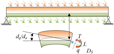
Figure 1. Schematic diagram of bridge loading under thermodynamic considerations
Figure 1 presents the schematic diagram of force distribution in the bridge from a thermodynamic perspective. Within this framework, both kinetic and potential energy densities are not only mechanisms for energy storage but are also closely related to wave propagation and interference phenomena. The kinetic energy density reflects far-field energy transmission characteristics, particularly the attenuation behavior of far-field waves, which is directly influenced by the material’s thermal conductivity and the propagation velocity of vibrational waves. In contrast, the potential energy density corresponds to interference effects induced by thermal stresses. Interactions between forward and backward propagating far-field waves result in spatial redistribution of energy. By applying time-periodic averaging to both energy densities, a clearer understanding can be achieved of how energy is transmitted and transformed within the bridge structure. The total energy density after both temporal and spatial averaging is given by the following expression:
$\langle\bar{e}\rangle=\frac{1}{2} \vartheta_t \mu^2\left(\left|X_1\right|^2 e^{2 j_{e 2} a}+\left|X_2\right|^2 e^{-2 j_{e 2} a}\right)$ (20)
In the analysis of energy flow, the fundamental variable from a thermodynamic perspective is the locally space-averaged energy density. During wave propagation, multiple reflections, refractions, and possible interference phenomena occur, which induce fluctuations in local vibration amplitudes. To obtain a stable representation of energy flow, it is necessary to apply local spatial averaging to the energy density, thereby eliminating localized fluctuations caused by wave interactions and propagation effects. This process enables the derivation of a smoothed energy distribution, which is essential for accurately characterizing energy transmission pathways, dissipation mechanisms, and transformation dynamics. The expression for vibrational energy flow under time-periodic averaging is given by:
$\begin{aligned} & \langle U\rangle=\frac{1}{2} \operatorname{Re}\left\{F_{E F F}^*\left[\left(\frac{\partial^3 \mu}{\partial a^3}\right)\left(\frac{\partial \mu}{\partial s}\right)^*-\left(\frac{\partial^2 \mu}{\partial a^2}\right)\left(\frac{\partial^2 \mu}{\partial a \partial s}\right)^*\right]-D_s^*\left(\frac{\partial \mu}{\partial a}\right)\left(\frac{\partial \mu}{\partial s}\right)^*\right\}\end{aligned}$ (21)
Through further local spatial averaging, variations in power flow caused by interference between traveling waves can be eliminated. In real bridge structures, wave propagation is influenced by various factors, particularly complex boundary conditions and material heterogeneity. Interference among traveling waves may lead to localized fluctuations in power flow, which can distort energy flow analysis. By averaging the energy within a spatial region, these local disturbances can be suppressed, yielding a more accurate representation of the overall power flow distribution.
By combining the obtained wave solutions with the above formulation and applying local spatial averaging, the time- and space-averaged power flow expression can be derived as:
$\left\langle e_j\right\rangle=\frac{1}{2}\left(2 F_{E F F} j_{e 1}^3-D_S j_{e 1}\right)\left(\left|X_1\right|^2 e^{2 j_2 a}-\left|X_2\right|^2 e^{-2 j_{{e2 }} a}\right)$ (22)
By comparing Eq. (20) with Eq. (22), the following relationship can be obtained:
$\langle\bar{U}\rangle=\frac{2 F_{E F F} j_{e 1}^3-D_S j_{e 1}}{2 \vartheta_t \mu^2 j_{e 2}} \bullet \frac{\partial\langle\bar{e}\rangle}{\partial a}$ (23)
By combining Eqs. (14) and (15) with the above expression, the resulting form is:
$\langle\bar{U}\rangle=-\frac{z_h^2}{\lambda \mu} \bullet \frac{\partial\langle\bar{e}\rangle}{\partial a}$ (24)
In energy flow analysis, the governing equation for energy density is derived based on the principle of energy conservation within a differential control volume. According to the first law of thermodynamics, the input, dissipation, and conduction of energy must satisfy a conservation balance. Through a detailed analysis of energy flow within the control volume, the energy flux density equation can be established, enabling the description of energy transmission, conversion, and dissipation processes in the system. For the adopted hysteretic damping model, prior research has demonstrated that time-periodic averaging yields an expression for the mean dissipated power associated with vibrational energy. This result provides a critical foundation for the subsequent derivation of the energy flow governing equation. The time-averaged dissipated power due to structural vibration is given by:
$o_{D I}=2 \lambda \mu\left\langle\bar{e}_o\right\rangle$ (25)
It can be concluded that the time- and locally space-averaged potential energy density is equal to the kinetic energy density. Based on this equivalence, the above expression can be reformulated as:
$o_{D I}=\lambda \mu\langle\bar{e}\rangle$ (26)
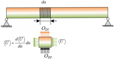
Figure 2. Schematic of energy flow balance in a differential control volume
Considering the energy balance relationship within the differential control volume illustrated in Figure 2, the following equation can be obtained:
$\langle\bar{U}\rangle+\frac{d\langle\bar{U}\rangle}{d a} d a-\langle\bar{U}\rangle+\lambda \mu\langle\bar{e}\rangle d a=o_{I N} d a$ (27)
By substituting Eq. (25) into Eq. (27), the governing equation for energy density can be established as:
$-\frac{z_h^2}{\lambda \mu} \bullet \frac{\partial^2\langle\bar{e}\rangle}{\partial a^2}+\lambda \mu\langle\bar{e}\rangle=o_{I N}$ (28)
The self-powered monitoring system developed in this study is based on the harvesting of mechanical energy from bridge vibrations. Electrical energy was generated through the integration of a “cantilever beam + mass block” piezoelectric unit and a contact-separation triboelectric mechanism. This combined system converts the mechanical energy inherent in bridge vibrations into usable electrical power, enabling autonomous operation without the need for external power sources. Specifically, when the bridge undergoes vibration, the cantilever beam experiences slight deformation due to inertial effects. This deformation induces alternating piezoelectric fields in the piezoelectric materials, which are subsequently converted into electrical energy. Simultaneously, the deformation causes contact and separation between the triboelectric electrodes and the triboelectric layer, generating additional triboelectric charges. Through the coupling of piezoelectric and triboelectric effects, electrical energy is simultaneously extracted via both mechanisms, thereby enhancing the overall energy harvesting capability of the system. This configuration enables efficient performance across multiple frequency bands, with particularly high efficiency in the low-frequency range below 10 Hz.
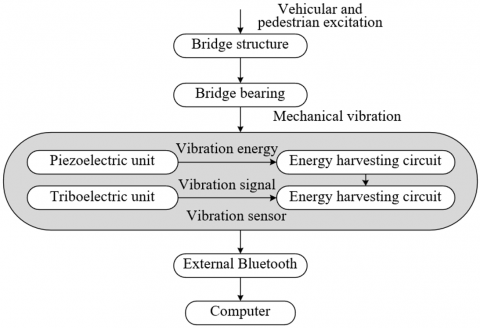
Figure 3. Design of the self-powered monitoring system based on bridge vibration energy harvesting
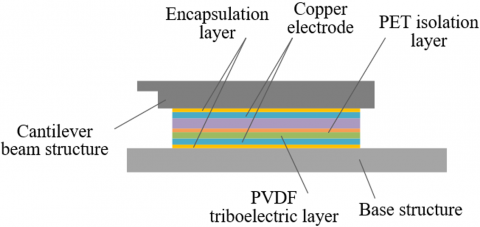
Figure 4. Schematic diagram of the triboelectric unit structure
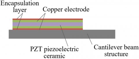
Figure 5. Schematic diagram of the piezoelectric unit structure
A notable feature of the proposed self-powered monitoring system lies in its ability to capture energy from minute structural vibrations and to use this energy to provide a stable power supply for bridge health monitoring. Since the system operates independently of external energy input, its reliability and autonomy are significantly improved. In practical implementation, the piezoelectric and triboelectric units are precisely integrated to effectively harness vibrational energy from each cycle, ensuring continuous and stable power delivery to the sensing modules. This ensures real-time acquisition and transmission of monitoring data. In addition, the structural design was optimized to adapt to varying vibration characteristics across different bridge types, thereby improving both environmental adaptability and operational efficiency. The design principle of the system is illustrated in Figure 3. Figures 4 and 5 present the schematic diagrams of the structure of triboelectric and piezoelectric units.
Bridge vibrations in practical scenarios are primarily induced by vehicular and pedestrian excitations. These vibrations are converted into electrical signals via sensors. However, the direct output of electrical signals from sensors is insufficient for effective monitoring and analysis. Therefore, appropriate circuit integration is required to process the weak signals generated by the sensors, improving both their stability and accuracy. Signal amplification circuits, filtering circuits, and signal conditioning circuits are typically employed to ensure that the output signals from the sensors are accurately captured and converted into usable data. The inclusion of such circuitry not only guarantees reliable signal transmission but also enhances the system’s ability to operate effectively under varying environmental conditions, thereby improving the quality of the collected data. Simultaneously, a wireless transmission technology—namely a Bluetooth device—was integrated to enable remote data transmission. This significantly reduces wiring complexity and improves both the flexibility and scalability of the system. By leveraging Bluetooth communication, sensor signals processed through the circuit modules can be transmitted in real time to a backend computing platform, facilitating remote monitoring and data analysis.
In practical operation, bridges are subjected not only to vertical vibrational excitations but also to horizontal accelerations, particularly under conditions of high traffic flow. Conventional single-cantilever beam configurations may fail to effectively resist horizontal excitations, potentially compromising the reliability of structural health monitoring. To address this, the self-powered monitoring system developed in this study adopts a circumferentially arranged multi-cantilever beam configuration, specifically designed to enhance the system’s stability and energy harvesting efficiency under horizontal excitation. The use of multiple cantilever beams arranged radially improves the system’s capacity to resist lateral vibrations by leveraging structural symmetry and distributing horizontal forces. Each cantilever beam undergoes measurable deformation when subjected to horizontal excitation, allowing the system to respond uniformly to multidirectional vibrations. This design minimizes the impact of external disturbances on monitoring accuracy and significantly improves the overall operational stability and reliability of the system. Specifically, the configuration of three cantilever beams arranged in a hexagonal geometry maximizes the effective length of each beam within a fixed structural footprint, thereby enhancing the deformation capacity of the piezoelectric units. This configuration allows for the efficient capture of small vibrational energies inherent in bridge operation, while avoiding the limitations of overly simplistic or asymmetric designs that typically suffer from insufficient energy harvesting. By fixing the three cantilever beams at the designated monitoring location and utilizing the vertical oscillation of a central mass block, sufficient deformation was induced in the piezoelectric elements, generating adequate electrical energy to sustain continuous self-powered monitoring. A schematic diagram of the piezoelectric unit structure is provided in Figure 5.
The proposed self-powered monitoring system was fabricated using an aluminum alloy base, sleeve, and encapsulation cover, with sufficient mechanical strength and durability in actual operation ensured by screw-fastened enclosure points. Aluminum alloy was selected due to its favorable mechanical properties, including high strength, corrosion resistance, and low weight, making it an ideal material for structural components. Encapsulating the sensor assembly within the aluminum base and sleeve provides robust protection against environmental interference, thereby extending device service life. Additionally, the excellent thermal conductivity of aluminum facilitates efficient heat dissipation, helping to maintain the thermal stability of both the sensor and associated circuitry. Given that long-term operational stability is essential for vibration monitoring systems, aluminum alloy encapsulation ensures reliable performance across a range of environmental conditions.
The experimental study was conducted using the main bridge of the Toutunhe Interchange Connector as the test platform. The site is located within a low mountainous valley geomorphological zone. The proposed bridge spans both banks of the Toutunhe River, where the riverbed elevation is approximately 847.8 m. The elevation at the crest of the eastern slope reaches 1010 m, resulting in a maximum elevation difference of approximately 162 m. The total length of the Toutunhe Interchange Connector Bridge is 2292 m, with a deck width of 19 m and a maximum height of 123.8 m. The main bridge consists of an 82+4×150+82 m continuous cast-in-place steel box girder structure. The substructure adopts pile foundations, with variable cross-section twin-cell hollow piers. The tallest pier reaches a height of 114.8 m. The west approach bridge comprises 16 spans of 40 m precast box girders, while the east approach bridge consists of a composite girder structure with spans of 12×60 m and 3×45 m. Hydraulic climbing formwork was used for pier construction, and a cantilever segmental method using form travelers was employed for the continuous girder. The terrain between Pier #0 and Pier #15 is relatively gentle, with slope angles ranging from approximately 15° to 20°. Between Piers #15 and #18, significant topographic variation was introduced due to recent mechanical excavation and backfilling. Notably, a steep artificial slope approximately 26 m in height exists between Piers #15 and #16; the upper section of this slope is nearly vertical, while the lower section exceeds 40° in inclination. Near Piers #17 and #18, artificially filled soil—recently deposited by mechanical means—was observed, with a maximum fill thickness exceeding 20 m. Between Piers #19 and #35, the terrain is mostly level, with local slopes approaching 20°. The segment spanning Piers #35 to #44 features slope gradients ranging from 20° to 45°, with localized sections exceeding 50°. The project site lies within a temperate continental climate zone and belongs to a semi-arid sub-temperate climatic classification.
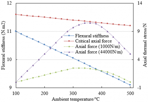
Figure 6. Influence of temperature on flexural stiffness and axial force during bridge vibration
According to the experimental results in Figure 6, as ambient temperature increased from 100℃ to 500℃, the flexural stiffness (represented by the blue line) exhibited a continuous decline, decreasing from approximately 11 N/m to around 9 N/m. This trend clearly indicates a weakening of structural rigidity with increasing temperature. In contrast, the critical axial force (represented by the red line) remained essentially stable, displaying minimal fluctuation, which suggests a relatively negligible sensitivity to temperature variation. Regarding axial force behavior, different axial spring stiffness coefficients—specifically 1000 N/m (green line) and 4400 N/m (purple line)—were examined. For both cases, the axial force initially increased and then decreased as the temperature rose. The 1000 N/m case showed a more gradual increase with temperature, while the 4400 N/m case exhibited a sharper rise, peaking between 300℃ and 400℃, followed by a pronounced decline. These results confirm that the mechanical behavior of the bridge structure during vibration is strongly influenced by temperature. The observed reduction in flexural stiffness with increasing temperature implies a temperature-induced alteration in the material’s mechanical properties, which may affect both structural stability and the efficiency of vibration energy harvesting. This relationship is particularly critical for the development of self-powered monitoring systems that rely on vibrational energy capture. Although the general trend of temperature-dependent axial force variation was consistent across different stiffness configurations, the extent of variation differed. This finding suggests that the magnitude of axial force serves as a significant factor influencing the thermal response. The critical axial force, however, remained largely unaffected by temperature, reflecting its inherent stability under thermal excitation.
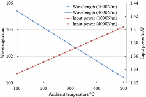
Figure 7. Influence of temperature on wavelength and input power during bridge vibration
Experimental data presented in Figure 7 reveal that as ambient temperature increases from 100℃ to 500℃, the vibration wavelength of the bridge—under both axial constraint spring stiffness conditions (1000 N/m and 4000 N/m)—exhibits a consistent downward trend (blue line), decreasing gradually from approximately 105 mm to a range between 100 mm and 102 mm. In contrast, input power (red line) displays a marked upward trend, progressively rising with temperature and reaching its maximum value at 500℃. The variation in input power under both stiffness conditions remains largely consistent in trend. These findings indicate that temperature exerts a pronounced effect on both the wavelength and input power during bridge vibration. The observed decrease in wavelength with increasing temperature suggests a thermally induced modification of the structural vibrational characteristics, likely attributable to thermal expansion or broader thermodynamic effects. Such wavelength reduction has direct implications for the energy harvesting mechanism based on structural vibration. Simultaneously, the increase in input power with temperature suggests that the efficiency of vibrational energy conversion into input power is enhanced at higher temperatures. This observation carries positive significance for the development of self-powered monitoring systems, as it implies the potential for greater energy acquisition under elevated thermal conditions. Furthermore, although the trends in wavelength and input power are similar for both axial constraint stiffness values (1000 N/m and 4000 N/m), the differences in absolute values indicate that the magnitude of axial force is also a critical factor influencing the vibrational energy characteristics of the bridge.
Figure 8. Influence of material changes and thermal stress on the bridge’s natural frequency
As shown in the experimental data in Figure 8, when only material changes were introduced (blue dotted line with circles), the natural frequency ratio of the bridge remained stable at approximately 0.8, showing no significant variation with respect to mode order. This indicates that material changes influence the natural frequency in a proportional manner. When only axial constraint with a spring stiffness coefficient of 1000 N/m was applied (red line with crosses), the natural frequency ratio started at approximately 0.9 and remained relatively constant thereafter. In the case of an axial constraint with a higher spring stiffness coefficient of 4000 N/m (green line with triangles), the natural frequency ratio increased rapidly to 1.0 at lower mode orders and then stabilized. This suggests that the influence of axial force on natural frequency varies with force magnitude and tends to stabilize beyond a certain mode order. The experimental results demonstrate that material changes and thermal stress exhibit distinct effects on the bridge’s natural frequency. Material changes result in a uniform and proportional reduction in natural frequency, independent of mode number, indicating a consistent impact on the global dynamic properties of the structure due to alterations in material characteristics. In contrast, the effect of axial force is dependent on its magnitude; axial constraint with a stiffness of 4000 N/m was observed to have a more pronounced enhancing effect on the natural frequency, with the influence becoming stable at higher modes.
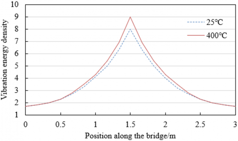
Figure 9. Influence of temperature on bridge vibration energy density
Figure 9 presents the variation in vibration energy density along the bridge at two different ambient temperatures: 25℃ (blue dashed line) and 400℃ (red solid line). A peak in energy density is observed near the 1.5 m position on the bridge for both temperature conditions, with the peak value at 25℃ reaching approximately 8, while at 400℃ it approaches 9. Both curves exhibit a general trend of increasing followed by decreasing energy density along the bridge span. However, at 400℃, the peak value is noticeably higher, and across most of the spatial domain, the energy density values at 400℃ exceed those at 25℃. These results indicate that temperature has a significant effect on the spatial distribution of bridge vibration energy density. The higher peak observed at 400℃ suggests that elevated temperatures can enhance the local vibration energy density at specific positions along the bridge.
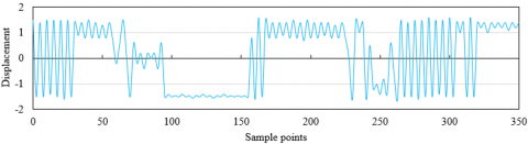
(a) Displacement
(b) Displacement rate of change
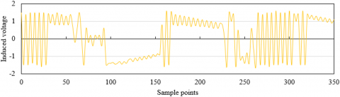
(c) Induced voltage
Figure 10. Sample response data of the self-powered monitoring system based on bridge vibration energy harvesting
As shown in Figure 10, displacement (blue curve) exhibits oscillatory behavior between sample points 0 and 350, with relatively large fluctuations observed in the initial and final segments. Around sample point 100, the amplitude of displacement fluctuations decreases significantly. The displacement rate of change (green curve) shows pronounced variation at the beginning and end, while remaining close to zero and stable in the middle segment.
The induced voltage (yellow curve) follows a trend similar to that of displacement, with reduced fluctuation in the central region and greater variability at both ends. These results demonstrate that the system response varies across different sample points. In the middle segment, multiple indicators exhibit relative stability. The response sample information reflects the dynamic changes of the output characteristics of the bridge vibration energy harvesting system with the sample points. The fluctuations observed in displacement and induced voltage reflect changes in bridge vibrational energy. A reduction in these fluctuations in the middle segment implies a more stable vibrational state or a certain equilibrium state of the system. The stabilization of the displacement rate of change in the central region further indicates a low rate of vibrational variation. In system design, it is necessary to fully consider the energy harvesting efficiency at different stages, especially to optimize the energy collection capability of the system under conditions of high variability, thereby ensuring robust energy capture during the dynamic changes in bridge vibration energy.
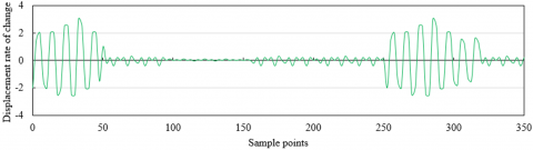
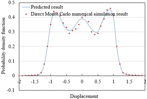
(a) Displacement
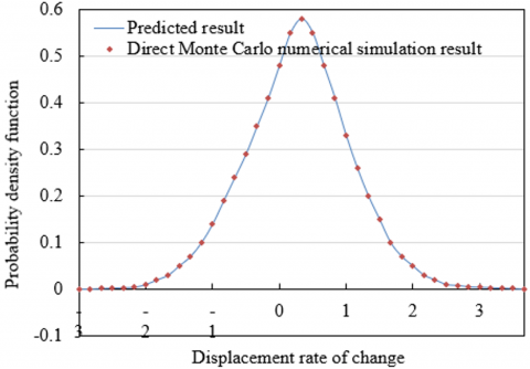
(b) Displacement rate of change
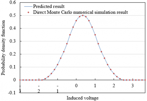
(c) Induced voltage
Figure 11. Comparison between the predicted result of the self-powered monitoring system and the direct Monte Carlo simulation result
In Figure 11, the displacement plot shows that the predicted results (blue curve) align closely with the direct Monte Carlo numerical simulation (red scatter points), with both capturing multiple peaks and troughs. Minor discrepancies are observed in local details. In the displacement rate of change plot, both datasets display similar profiles, peaking in the middle and tapering off toward the ends. In the induced voltage plot, both the predicted and simulated values reach a maximum in the central region and decrease symmetrically toward the boundaries. These results confirm that the prediction model effectively captures the overall system response, closely approximating the results of Monte Carlo simulations. Although slight local deviations exist, the overall agreement validates the predictive capability of the model. This has significant implications for the development of the vibration-based energy harvesting and self-powered monitoring system. The model provides a reliable tool for performance evaluation, reducing the dependency on large-scale Monte Carlo simulations and thereby enhancing the efficiency of system development.
Based on a thermodynamic perspective, the development of a bridge vibration energy harvesting and self-powered monitoring system was investigated in depth. An energy flow model describing bridge vibration was first constructed, through which the energy transmission and transformation processes under various vibrational excitations were systematically analyzed. A comparative analysis of different vibration sources—such as vehicular traffic, wind loads, and seismic activity—was performed to evaluate their respective influences on energy harvesting efficiency. Subsequently, a novel self-powered monitoring system based on vibration energy harvesting was proposed. This system was designed to continuously supply electrical power to structural health monitoring devices by utilizing the vibrational energy inherent in the bridge itself. The system architecture integrated optimized configurations of energy harvesters, power conversion units, and energy storage components to ensure high operational efficiency under practical conditions. The system's energy harvesting capability and output power stability were validated through a combination of experimental testing and numerical simulations across various operating scenarios. The results confirmed that the system is capable of effectively capturing bridge vibration energy and reliably delivering stable power to monitoring devices.
Taken together, this study offers an innovative solution for converting bridge vibration energy into usable electrical power through the combined development of a vibration-based energy flow model and a self-powered monitoring system. The proposed system demonstrated high energy harvesting efficiency and stable electrical performance in real-world applications, substantially enhancing the continuity and reliability of bridge health monitoring. The study is marked by both novelty and practicality, as it represents the first comprehensive thermodynamic analysis of bridge vibration energy capture and introduces a fully integrated self-powered system architecture. A power-independent monitoring solution was provided, showing strong potential for practical deployment, particularly in remote or energy-inaccessible bridge structures. Additionally, the system’s reliance on ambient vibration enhances energy utilization efficiency and contributes to broader energy-saving and environmental benefits.
However, certain limitations remain in this study. Despite the optimization of system design, energy harvesting efficiency under low-frequency or weak vibrational conditions requires further improvement. In addition, the system’s long-term stability and durability under extreme environmental conditions—such as severe weather or seismic events—have yet to be fully validated and must be further enhanced. The initial design and installation costs are relatively high, and the long-term maintenance demands and associated operational costs require comprehensive evaluation. Future research should prioritize the refinement of energy harvesting techniques, including the development of advanced materials and devices capable of achieving higher energy conversion efficiency across a broader range of vibrational scenarios. Emphasis should also be placed on the design of more durable components to improve system stability and service life under extreme conditions. The integration of Internet of Things and artificial intelligence technologies is expected to enhance the system’s level of automation and intelligent monitoring capabilities, thereby enabling more accurate assessment of bridge health status. Moreover, the economic feasibility of the system should be thoroughly investigated, with design optimizations aimed at reducing costs and increasing the viability of large-scale commercial deployment. Through such advances, it is anticipated that future iterations of bridge vibration energy harvesting and self-powered monitoring systems will offer greater efficiency, reliability, and cost-effectiveness, providing robust technical support for the safety and maintenance of bridge infrastructure.
[1] Apaydın, N.M., Kaya, Y., Şafak, E., Alçık, H. (2012). Vibration characteristics of a suspension bridge under traffic and no traffic conditions. Earthquake Engineering & Structural Dynamics, 41(12): 1717-1723. https://doi.org/10.1002/eqe.1196
[2] Paeglitis, A., Paeglitis, A. (2014). Traffic load models for Latvian road bridges with span length up to 30 meters. The Baltic Journal of Road and Bridge Engineering, 9(2): 139-145. https://doi.org/10.3846/bjrbe.2014.18
[3] Skokandić, D., Mandić Ivanković, A. (2022). Value of additional traffic data in the context of bridge service-life management. Structure and Infrastructure Engineering, 18(4): 456-475. https://doi.org/10.1080/15732479.2020.1857795
[4] Rizqiansyah, A., Caprani, C.C. (2024). Hierarchical Bayesian modeling of highway bridge network extreme traffic loading. Structural Safety, 111: 102503. https://doi.org/10.1016/j.strusafe.2024.102503
[5] Yanez-Borjas, J.J., Machorro-Lopez, J.M., Camarena-Martinez, D., Valtierra-Rodriguez, M., Amezquita-Sanchez, J.P., Carrion-Viramontes, F.J., Quintana-Rodriguez, J.A. (2021). A new damage index based on statistical features, PCA, and Mahalanobis distance for detecting and locating cables loss in a cable-stayed bridge. International Journal of Structural Stability and Dynamics, 21(9): 2150127. https://doi.org/10.1142/S0219455421501273
[6] Mackie, K.R., Wong, J.M., Stojadinovic, B. (2011). Bridge damage and loss scenarios calibrated by schematic design and cost estimation of repairs. Earthquake Spectra, 27(4): 1127-1145. https://doi.org/10.1193/1.3651362
[7] Miyamoto, A., Motoshita, M.A. (2017). Study on the intelligent bridge with an advanced monitoring system and smart control techniques. Smart Structures and Systems, 19(6): 587-599. https://doi.org/10.12989/sss.2017.19.6.587
[8] Miyamoto, A., Yabe, A., Hradil, P., Hakola, I. (2024). Feasibility study on intelligent bridge combined with smart monitoring techniques. Structure and Infrastructure Engineering, 20(7-8): 1133-1148. https://doi.org/10.1080/15732479.2023.2276896
[9] Bas, S., Apaydin, N.M., Ilki, A., Catbas, F.N. (2018). Structural health monitoring system of the long-span bridges in Turkey. Structure and Infrastructure Engineering, 14(4): 425-444. https://doi.org/10.1080/15732479.2017.1360365
[10] Skibniewski, M., Tserng, H.P., Ju, S.H., Feng, C.W., et al. (2014). Web-based real time bridge scour monitoring system for disaster management. The Baltic Journal of Road and Bridge Engineering, 9(1): 17-25.
[11] Infantes, M., Castro-Triguero, R., Sola-Guirado, R.R., Bullejos, D., Friswell, M.I. (2023). A feasibility study on piezoelectric energy harvesting from the operational vibration of a highway bridge. Advances in Structural Engineering, 26(2): 205-217. https://doi.org/10.1177/13694332221120129
[12] Wei, G., Lin, T. (2024). Optimization of the performance and operation of a photovoltaic-thermoelectric power supply system for bridge safety monitoring microsystems. Case Studies in Thermal Engineering, 57: 104387. https://doi.org/10.1016/j.csite.2024.104387
[13] Sazonov, E., Li, H., Curry, D., Pillay, P. (2009). Self-powered sensors for monitoring of highway bridges. IEEE Sensors Journal, 9(11): 1422-1429. https://doi.org/10.1109/JSEN.2009.2019333
[14] Ahmad, M.M., Khan, N.M., Khan, F.U. (2023). Bridge vibration energy harvesting for wireless IoT-based structural health monitoring systems: A review. Journal of Intelligent Material Systems and Structures, 34(19): 2209-2239. https://doi.org/10.1177/1045389X231180040
[15] Zhou, Z., Zhang, H., Qin, W., Zhu, P., Wang, P., Du, W. (2021). Harvesting energy from bridge vibration by piezoelectric structure with magnets tailoring potential energy. Materials, 15(1): 33. https://doi.org/10.3390/ma15010033
[16] Yang, H., Chen, Q., Liu, H., Chang, H., Yang, S. H., Wang, L., Liu, P. (2022). Investigation on distributed vibration damping of bridge based on energy harvesting technique and finite element analysis. Applied Sciences, 13(1): 382. https://doi.org/10.3390/app13010382