Asmaa Ali Hussein*![]() | Mohammed Abood Habib
| Mohammed Abood Habib![]() | Faris Ali Badawy
| Faris Ali Badawy![]() | Kadhum Audaa Jehhef
| Kadhum Audaa Jehhef![]()
© 2025 The authors. This article is published by IIETA and is licensed under the CC BY 4.0 license (http://creativecommons.org/licenses/by/4.0/).
OPEN ACCESS
Thermofluids properties inside the pipe bend with a heat source in the bending section are investigated numerically. In this study, a U-bend pipe with constant diameter and length is utilized for the geometry of 1.5 lengths of inlet and outlet sections and a diameter of 0.5 m equipped with the rectangular heating source with heater width to diameter ratio was w/d=0.06, 0.13, 0.21, and 0.26. The heat power input was varied by 100, 200, 400, and 600 W/m2, and the air flow at Reynolds numbers in the range of 380, 760, 1100, and 1500. The control volume technique was accomplished by ANSYS-Fluent v.2020 to solve a steady, laminar, and fully developed flow with no-slip wall conditions. Air is employed as a working fluid, assuming it is continuous. The continuity equation and the Navier-Stokes equations have been solved. In conclusion, the results showed that the maximum Nu increased by 12, 24, 32, and 45% as used cases of width-to-diameter ratio (w/d = 0.06, 0.13, 0.21, and 0.26) respectively. However, the rate of heat transfer of the source U-tube was augmented by increasing the Reynolds number and the power of the source, and this led to an increase in the Nu was comparable to the coefficient of the heat transfer, and the rate of heat transfer also increased dramatically.
no-slip conditions, flow structure, heat source, laminar, incompressible, U-bend pipe
Secondary movements in cross sections perpendicular to the stream-wise direction and lateral surface slope characterize the flow structure in a curved channel. Power plants, the food industry, oil and gas firms, and petrochemical operations are just a few of the industrial sectors that use fluid movement and heat transfer inside a pipe bend with a heat source. Numerical prediction of turbulent flow in curved channels is more complex than laminar flow prediction because an anisotropic turbulent model is required to accurately forecast flow behavior. The flow fields at U-bends are highly complex, consisting of secondary cross-stream and radially outward flows due to the pressure gradient and centrifugal forces [1].
Azzola et al. [2] using laser-Doppler measurements of the circumferential and longitudinal velocity components, turbulent flow in a severely curved 180-degree conduit and its downstream tangent are developed. The mean longitudinal velocity component is very steady when θ=90 degrees, while the circumferential component never fully emerges. The data at the bend, including the secondary flow reversals, coincides with the estimated behavior quite well. The same problem with the turbulence model that was seen in the flow recovery zone over a backward-facing step is evident downstream of the bend, where the flow recovers too slowly. Usui et al. [3] provided experimental findings on the average void percentage, slip ratio, phase distribution, and flow behavior of the grouping of two-phase water and air passing through an inverted U-bend. The transparent acrylic resin tubing test section was curved and had a 24 mm I.D. It included a downcomer, a riser, and an inverted U-bend with a radius of 96 mm. A flow map that shows the relationship between flow patterns and velocities was created using visual observation. Hidayat and Rasmuson [4] assert that the U-bends in the pneumatic conveying dryer system raise the slip velocities between the drying medium and suspended material, which significantly affects drying behavior. Two-phase CFD calculations using an Eulerian–Eulerian model and the commercial program Fluent 6.0 were used to calculate the gas and particle flows in a U-bend. Among the factors being examined are particle density, bend radius ratio, gas velocity, particle diameter, and particle volume %. Validation of the numerical computations was done using experimental data from the literature. Hidayat and Rasmuson [5] used FLUENT 6.0 to numerically study the incompressible, single-phase and multiphase, isothermal, and steady-state flows in a U-bend. For instance, a basic understanding of gas-solid flow and pressure behavior in a U-bend may be necessary to improve the design of U-bends in pneumatic conveying dryers. Fyhr and Rasmuson found that U-bends significantly affected the drying behavior in such a dryer because they enhance the velocity differences (slip) between the drying liquid and suspended material. de Matos and Franca [6] examined numerical and experimental results on the phase distribution of bubbly liquid-gas flows occurring inside a square-cross-section conduit. The main focus is on the phase segregation that occurs when the mixture passes over a U-bend curve from 1 g to 7 g, where mild centrifugal forces are acting on the bubbly flow. The action of centrifugal forces led the gas bubbles along the U-bend curve to be moved to the inner curve portion. Cvetkovski et al. [7] studied vertical loops, which consist of two pipes connected by a U-bend at the bottom. The U-bend portion produces vortical shapes and turbulence, which enhance heat transmission. Vortical forms and flow turbulence are influenced by Reynolds and Dean numbers. Downstream of the U-bend, the massive vortex formations can persist for many diameters. It has been demonstrated that raising the Dean number considerably extends the life of vortex formations for high Reynolds number flows. Aliyu et al. [8] presented an experimental study in 2016 on the flow behavior of gas and liquid in the top section of a vertical pipe system with a serpentine shape and an internal diameter of 101.6 mm. The experimental matrix includes surface gas and liquid velocities that span bubbly to annular flow, with ranges of 0.15 to 1.5 m/s. The patterns, however, are different from those of small-diameter pipes, where the film thickness drops down far more quickly as the gas flow increases. Consequently, the experimental results for big pipe film thickness did not agree with several of the reported correlations for small pipe data. As a result, we adjusted one of the top-performing correlations, leading to a better match. Hufnagel [9] focused on the turbulent flow through a θ=90° pipe bend that is preceded and followed by straight pipe segments. This was done by direct numerical simulation. Examining a pipe with curvature 0.3, the ratio of the pipe radius to the bend radius, for a bulk Re=11700, yields the friction Reτ≈360. Synthetic turbulence is produced in the inflow section in place of the conventional recycling method to avoid interference between swirl-switching frequencies and recycling. A heated flow of supercritical R134a in horizontal U-bend tubes was studied numerically by You et al. [10]. At a constant pressure (1.05 times the critical pressure), numerical runs were performed with varying mass flow, heat flux, tube diameters, and bend curvatures after model validation against experimental data from U-tube and straight tubes. Results show that under mixed convection, the U-bend significantly affects flow and heat transfer in and downstream of the U-bend, but only slightly affects heat transfer in the straight section preceding it. Kükrer and Eskin [11] conducted an experimental investigation of air-water flow in a whole pipe system, including the two-phase flow development in the injector, upstream, U-bend, and downstream regions separately. Bubble counts and local void fractions were measured with a dual optical probe. Through a 40 mm diameter pipe, the circular injector was intended to supply two-phase flow conditions with water flow rates of 180 l/min and air flow rates of 30, 35, and 40 l/min. To numerically solve the Navier-Stokes equations for the laminar flow system with a low Reynolds number, Rashed et al. [12] used a three-dimensional framework. Procedures for generating fluid-structure interactions through the impact of an Al2O3-water nanofluid at 0.1-1.0 vol. % volume fraction on the thin plate are described in the paper using COMSOL Multiphysics 5.4 [13]. The temperature distribution and velocity profile data of cold and hot nanofluids in a T-mixer are predicted by Abas Siba using a numerical simulation approach [14]. They investigated the mixing zone of a nanofluid flow in a T-shaped mixer with 50 nm Al2O3 nanoparticles flowing at Φ=0.4 vol.%. Temperature and flow velocity estimation in a T-mixer has been investigated using a 2D computational domain simulation of steady-state nanofluid flow. The lid-driven is widely employed in coating, drying, and mixing applications and is a significant problem in the research of fluid field and thermal performance rate, according to Jehhef et al. [15], numerical analysis is used to examine the temperature distribution and fluid flow in a lid-driven hollow with an upper oscillating surface and an attached baffle. The walls of the right and left cavities were maintained at 293 K and 350 K, respectively. An experimental set-up designed to allow investigations of the carrier fluid local behaviours in terms of velocity and temperature fields is presented by Mohamed et al. [16]. The study is carried out on a U-turn microfluidic channel to provide a complete view of the thermo-fluidic system. The general characteristics of critical heat flux (CHF) have been extensively explored in straight and continuously curved channels. However, studies in locally curved geometries like U-tube, which are also widely found in heat exchangers, were rather limited. Numerically investigating CHF in U-tube and reports some unique phenomena by comparing with straight tubes by Pan et al. [17].
This study proposes a numerical modeling methodology by utilizing the finite volume method that solves the governing equations of the airflow by ANSYS-FLUENT v-2020 to study the effect of an attached heat source with variable width to tube diameter located in the U-bend section on the temperature and velocity distribution. The paper's impartial is to investigate the enhancement of the Nusselt number and Dean number with a study of the effect of princes of heater source in the bending section on the pressure drop and friction factor and the fluid flow properties with constant diameter U-bend tube and with 180-degree bend duct is more useful to convey fluid.
2.1 Problem description
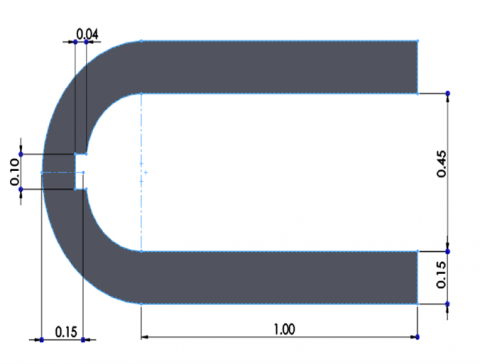
The testing of a numerical algorithm for describing cold airflow in a cylindrical U-bend duct with an angle of 108 degrees, with a rectangular heat source located in the bend section, and the airflow with laminar problems of isothermal flow as exposed in Figure 1. The present model consists of a duct of U-bend with an inlet and outlet section of 1 m length and a round U-bend with an outer radius of 0.55 m and inner radius of 0.4 m. The heater dimensions vary by the heater width to pipe diameter ratio w/d=0.06, 0.13, 0.21, and 0.26. The cold air is inter from the upper section, but the hot air flows exits from the lower section of the U-bend. In comparison, the diameter of the tube is fixed at 0.15 m. Hence, mixed convection occurs due to the forced convective heat transfer mechanisms caused by the airflow and the heater. In this study, the walls of the U-bend cylinder duct are fixed at adiabatic boundary conditions. The right heated fence is fixed at a constant heat flux of 100, 200, 300, and 400 W/m2; the left cold wall is fixed at a cold temperature of 305 K.
2.2 Assumptions and governing equations
To simulate the airflows and heat transfer in a U-bend duct, a numerical technique of modeling air flows was carried out within the framework of the hydrodynamic approach, based on the solution of the Navier–Stokes equations. It is known that the concept of continuum for fluid works if it is possible to single out the hydrodynamic physically infinitely small scale so that fluctuations inside the corresponding volume can be neglected. For liquid, when studying single-phase cavity, nonisothermal flows of multicomponent mixtures in the general case of air, which are described by the following system of equations, if are introduced into consideration – mass concentrations of mixture components. The 2D steady-state continuity, momentum, and energy equations at constant thermo-physical characteristics explain the fluid flow and heat transfer, the evolution of which is primarily established in the current work [18].
Figure 1. Schematic drawing of the physical domain (all dimensions in m)
The equation of continuity is:
$\frac{\partial}{\partial x_i}\left(\rho u_i\right)=0$ (1)
The equation of momentum is:
$\frac{\partial}{\partial x_i}\left(\rho u_i u_j\right)=\frac{\partial P}{\partial x_i}+\frac{\partial}{\partial x_i}\left[\mu\left(\frac{\partial u_i}{\partial x_j}+\frac{\partial u_i}{\partial x_i}-\frac{2}{3} \delta_{i j}+\frac{\partial u_i}{\partial x_j}\right)\right]$ (2)
2.3 The key parameters of flow and heat transfer
The entrance Re may be defined as follows, since the intake air flows with a uniform, constant average velocity of (Uav) [19]:
$R e=\frac{\rho U_{a v} D}{\mu}$ (3)
And the Prandtl number is given by:
$P r=\frac{\mu C p}{k}$ (4)
And
$D_h=\frac{4 P}{A_c}$ (5)
Heat flux in the test section is determined as follows [20]:
$q^{\prime \prime}=\frac{\dot{m}_w C p_w\left(T_{\text {in }}-T_{\text {out }}\right)}{A_s}$ (6)
Also, the heat transfer coefficient of the base fluid and air can be calculated as follows:
$h=\frac{q^{\prime \prime}}{\left(T_w-T_f\right)}$ (7)
Nusselt number is defined as:
$N u=\frac{h D_h}{k}$ (8)
2.4 Boundary conditions
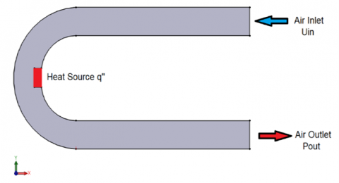
Each of the problems considered in the paper on setting the boundary conditions is discussed separately in Figure 2 said separately. It will be noted only general points. As boundary conditions on U-bend walls for the velocity vector components in most of the considered problems, no-slip conditions were used.
$v_x=v_y=0$. For problems of heat transfer on the walls, the conditions were also set at fixed temperatures in the inlet of cold and hot air flow but the inlet velocity was varied by (0.01, 0.02, 0.03 and 0.04 m/sec) and the source heater was considered as constant heat flux are 100, 200, 400, 600 W/m2. At the entrance to the computational domain, the Dirichlet conditions were overwhelmed: a fixed value of temperature, concentration, and average flow rate, with a steady velocity profile. The requirements were specified for the equality of derivatives concerning the normal to zero at the departure from the computational domain. The upwind QUICK second-order technique is used to approximate the convective elements of the transport equations. Second-order accurate techniques were utilized to estimate diffusion fluxes on facial control volumes. An implicit second-order technique was utilized to approximate the non-stationary parts of the equations. Naturally, the issue of how the accuracy of computations is affected by the computational grid's detail and quality comes up when examining the outcomes of numerical simulation. In each of the tasks considered in the dissertation, this issue was also studied in detail. Because the geometry of the considered mixing tee, as a rule, was topologically simple, then for calculations, and structured Cartesian grids were used. In many cases, the concentration of grid nodes in the most critical areas was used: near-wall region, mixing layer, flow junctions, etc. In methodical calculations, in detail, the effect of refinement of the computational grid was studied to obtain the corresponding grid-independent solutions.
Figure 2. The boundary condition used in this simulation
2.5 Grid generation and mesh independence test
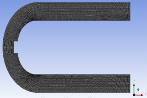
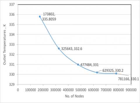
To determine how mesh size affected the outcomes, a grid-independent test using water was conducted. Three sets of hexagonal mesh, each measuring 100×100, 150×150, and 200×200, were created to determine the ideal grid size. The values of Nu were created to be equivalent to a 2% error for three different grid sizes. Therefore, a 200×200 mesh size was chosen to save computation time. Using the flow of air, they examined laminar convective heat transfer in a microchannel with longitudinal fins. Figure 3 depicts the single and double-domain mesh creation. The standard procedure to check how independent the grid is to perform the simulation at a higher resolution. The original grid is likely sufficient if the results are not significantly different. Calculations have been done for four chosen grid sizes: 173802, 325643, 477484, 629325, and 781166. It noted that the 141670 and the 177875 nodes gave nearly similar results. Therefore, the domain of 177875 nodes was selected as it enhances the computational accuracy and brings down the time of computation to provide a suitable mesh, as shown in Figure 4.
Figure 3. Mesh generation of single and double domains
Figure 4. Mesh independence test results
In this work, the temperature and velocity distribution profile of air-forced flow inside a U-bent tube at 180° degrees of rotation with a rectangular heat source located on the inner surface of the U-bending section are analyzed using a numerical simulation approach. By using a two-dimensional approach with a cold inlet air in the upper section and an outlet hot outlet air in the lower section of the duct was structured. First, the heater width-to-diameter ratio was varied by w/d=0.06, 0.13, 0.21, and 0.26, and the heat power input was varied by 100, 200, 400, and 600 W/m2, and the airflow with Reynolds number in the range of 380, 760, 1100, and 1500. The control volume technique was used with ANSYS-Fluent-v2020 to solve a steady, laminar, and fully developed flow with no-slip wall conditions, under various operating situations are covered.
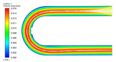
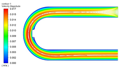
w/d=0
w/d=0.06
w/d=0.13
w/d=0.21
w/d=0.26
Figure 5. Air velocity streamlines for various (w/d) at Re=380 and q’’=100 W/m2
w/d=0
w/d=0.06
w/d=0.13
w/d=0.21
w/d=0.26
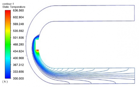
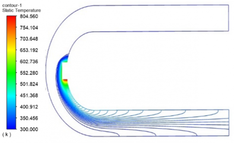
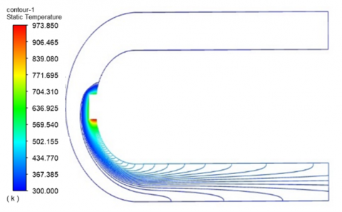
Figure 6. Temperature isotherms lines for various (w/d) at Re=380 and q’’=100 W/m2
3.1 Effect of rotation speed
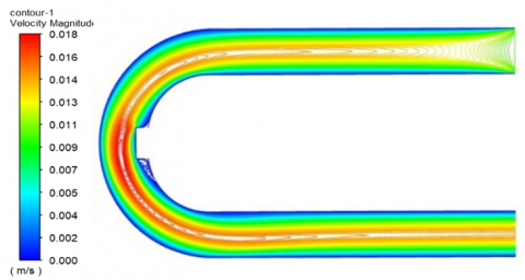
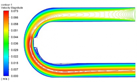
In Figures 5 and 6, the stream function for the case without a heat source w/d=0 was presented in the first part of the work to predict the outcome of increasing the ratio of heating source width-to-diameter (w/d). The effect of four scenarios of the ratio of width-to-diameter (w/d=0.06, 0.13, 0.21, and 0.26) on the temperatures and velocity stream function contours. U-bend geometry influenced the downstream flow pattern in both cases. The core-annular flow pattern is found in high superficial velocity of air. Plug flow is reported at high water velocity in the U-bend. Because of the smaller pipe sizes used in this study, the fouling angle and total pressure gradient are unaffected by flow direction via the return curve. Further analysis of the secondary motion, also referred to as flow streamlines, is done to examine how the secondary flow diminishes as it travels downstream from the pipe U-bend. The secondary velocities for the various curve radii and the bulk velocity are used to normalize the secondary velocity. The secondary flow, which is visible, reaches its maximum amplitude when it exits the 180-degree turn. The simulations with bend radii in the range contain two peaks at magnitudes of the same order, as can be seen here. Near the wall, where there is a significant secondary flow, the first peak is seen, then as one moves into the pipe's center, a second peak is seen.
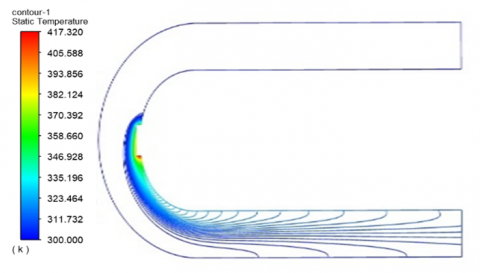
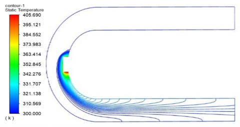
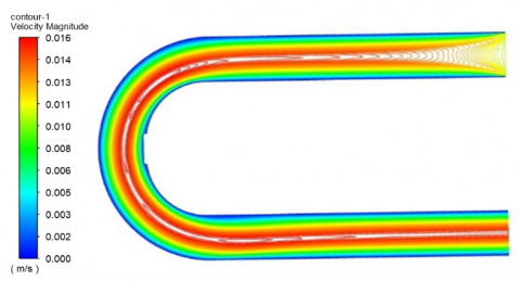
q’’=100 W/m2
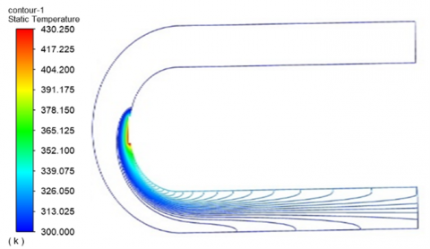
q’’=400 W/m2
q’’=600 W/m2
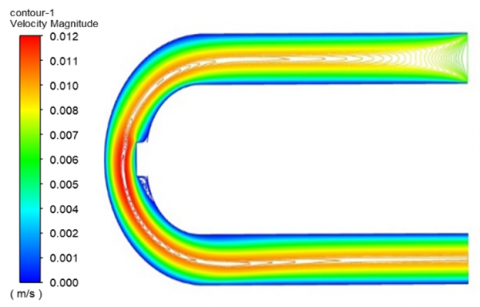
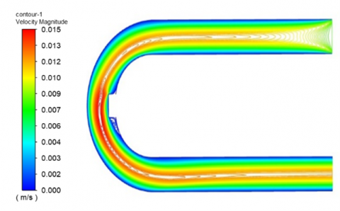
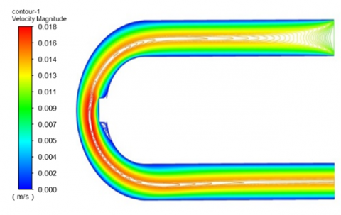
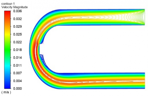
Figure 7. Air velocity streamlines for various heat power inputs at Re=380 and w/d=0.26
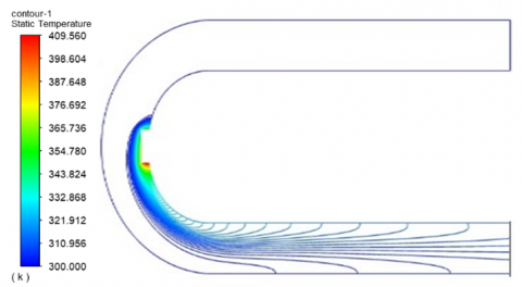
q’’=100 W/m2
q’’=400 W/m2
q’’=600 W/m2
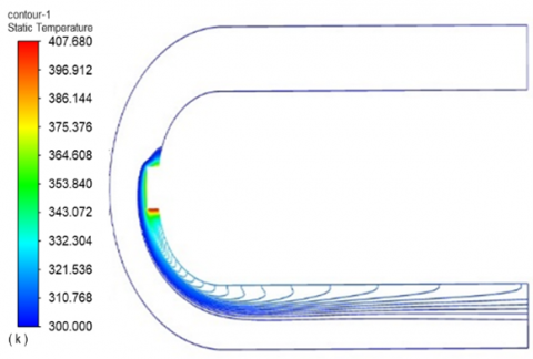
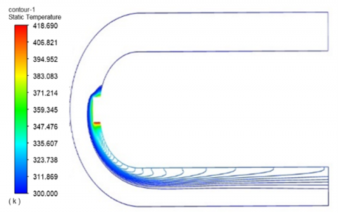
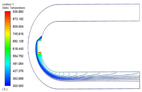
Figure 8. Temperature isotherms lines for various heat power inputs at Re=380 and w/d=0.26
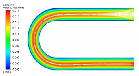
Re=760
Re=1100
Re=1500
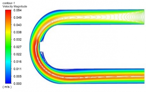
Figure 9. Air velocity streamlines for various inlet Reynolds numbers at q’’=100 and w/d=0.26
Re=760
Re=1100
Re=1500
Figure 10. Temperature isotherms lines for various inlet Reynolds numbers at q’’=100 and w/d=0.26
3.2 Effect of heat power
Lastly, the accuracy was determined by simulating the well-known benchmark problem, the U-bend duct flow of Newtonian air fluid flow, before acquiring the findings for the flow across the U-bend duct. As seen in Figures 7 and 8, the current findings for the maximum and lowest values of the y-component of velocity U at the center line that is located in the heat source section are discovered to be within ± 4% for air flow fluids. The results show that the maximum velocity is located in the case of w/d=0.26, due to the decrease in the cross-sectional area of the air flow. Figures 9 and 10 show the effect of Reynolds number on the air velocity and temperatures. This fosters confidence in the utilization of the solution techniques employed in this study.
Figure 11. Temperature isotherms (right) and air velocity streamlines (left) for various heat power inputs at Re=380 and w/d=0.26
Figure 12. Temperature isotherms (right) and air velocity streamlines (left) for various heat power inputs at Re=380 and w/d=0.26
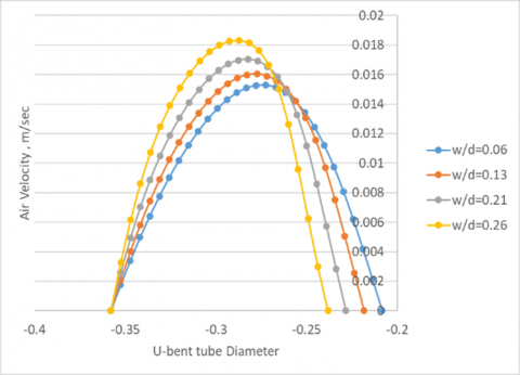
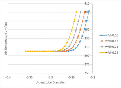
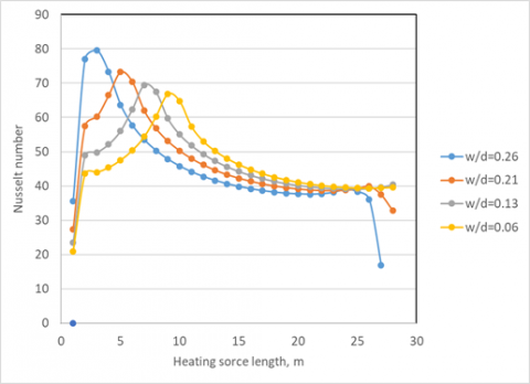
Additionally, Figures 11 and 12 show the influence of the width-to-diameter ratio on air velocity and temperature profile. The findings show that increasing the width w of the rectangular heating source leads to the maximum temperature being found at w/d=0.26. Also, Figure 13 illustrates how the width-to-diameter ratio affects the cavity's average Nu number. Increasing the width-to-diameter ratio (w/d) and Ra number will frequently increase Nu, except for those with the smallest pore diameter. However, the permeability of the porous media is extremely poor at small pore sizes, which inhibits fluid from naturally convecting through it. Based on the width-to-diameter ratio (w/d=0.06, 0.13, 0.21, and 0.26), the findings indicated that the maximum Nusselt number rose by 12, 24, 32, and 45%, respectively. Since the Nusselt number is directly related to the heat transfer coefficient, the finned tube heat exchanger's heat transfer rate also increases when the Reynolds number increases with rising air velocity. The rate of heat transmission increases as a result. It is found that the inner Nusselt number, convective heat transfer coefficient, and total heat transfer coefficient all increase with the coil side fluid flow rate.
Figure 13. Nusselt number for various source heater widths to U-bend tube diameter (w/d) at Re=380 and q’’=100 W/m2
A simulation analysis of forced convection of airflow in the 180-degree U-bend circular duct with a heating source in the middle of the inner bending section is presented in this work. The CFD methodology and finite volume method were used to solve the problem. More precisely, the primary computational task was a parametric analysis of the effect of flow velocity and curvature on the thermal distribution process within the U-bends, especially in terms of rising Re. During the low (Re=380, 760, 1100, and 1500) examples, it was demonstrated that the composite bend behaved rather similarly to the conventional one. Along with the heating source power input of 100, 200, 300, and 400 W/m2 effects, some preliminary evidence of more complicated phenomena about flow impingement and separation was also discovered. A more divergent pattern was seen in the mild instance of Re=1100. For both geometries, it was described how the thermal boundary layers from the upstream straight pipe were eliminated and how numerous secondary cells appeared. Nevertheless, a more noticeable attenuating influence on the secondary flow of the second elbow bend was seen, whereas a duct with a heater source of w/d=0.26 showed a larger tendency for separation at the inner bend side. The high case of (Re=1500) demonstrated the distinct behavior of the U-bends under investigation: several secondary cells were seen, but the Duct appeared to interfere with temperature and flow fields more severely. According to the results, the maximum Nusselt number rose by 12, 24, 32, and 45% in the situations where the width-to-diameter ratio was employed (w/d=0.06, 0.13, 0.21, and 0.26), respectively.
|
f |
friction factor |
|
g |
gravitational acceleration (m /s2). |
|
L |
length of axial (m). |
|
p |
pressure, (Pa). |
|
r |
coordinate of the radial axis. |
|
Γ |
tensor of stress. |
|
D |
deformation rate tensor. |
|
Dh |
hydraulic diameter (m) |
|
Uo |
axial velocity bulk inlet, (m/s). |
|
u |
x-direction velocity, (m/s). |
|
v |
r-direction velocity, (m/s). |
|
x |
Axial distance of artery model (m). |
|
Um |
Mean fluid velocity over the cross-section. |
|
Ac |
cross-sectional area of the flow (m2) |
|
As |
Heat transfer area (m2 |
|
k |
Thermal conductivity (W/(m⋅K) |
|
h |
Heat transfer coefficient of fluid W/m2K |
|
Subscripts |
|
|
μ |
viscosity, (Pa.s). |
|
λ |
constant of time, (s). |
|
γ |
rate of shear stress, (s-1). |
|
Δ |
gradient. |
|
ρ |
density (kg/m³). |
|
τ |
shear stress (N/m2) |
|
υ |
kinematic viscosity, (m2/s). |
[1] Cheah, S.C., Iacovides, H., Jackson, D.C., Ji, H., Launder, B.E. (1996). LDA investigation of the flow development through rotating U-ducts. Journal of Turbomachinery, 118(3): 590-596. https://doi.org/10.1115/1.2836706
[2] Azzola, J., Humphrey, J.A.C., Iacovides, H., Launder, B.E. (1986). Developing turbulent flow in a U-bend of circular cross-section: Measurement and computation. ASME Journal of Fluids Engineering, 108(2): 214-221. https://doi.org/10.1115/1.3242565
[3] Usui, K., Aoki, S., Inoue, A. (1983). Flow behavior and phase distribution in two-phase flow around inverted U-bend. Journal of Nuclear Science and Technology, 20(11): 915-928. https://doi.org/10.1080/18811248.1983.9733489
[4] Hidayat, M., Rasmuson, A. (2004). Numerical assessment of gas–solid flow in a U-bend. Chemical Engineering Research and Design, 82(3): 332-343. https://doi.org/10.1205/026387604322870444
[5] Hidayat, M., Rasmuson, A. (2005). Some aspects on gas–solid flow in a U-bend: Numerical investigation. Powder Technology, 153(1): 1-13. https://doi.org/10.1016/j.powtec.2005.01.016
[6] de Matos, A., Franca, F.A. (2009). Bubbly flow segregation inside a U-bend pipe: Experimentation and numerical simulation. Chemical Engineering Research and Design, 87(5): 655-668. https://doi.org/10.1016/j.cherd.2008.08.015
[7] Cvetkovski, C.G., Reitsma, S., Bolisetti, T., Ting, D.S. (2015). Heat transfer in a U-Bend pipe: Dean number versus Reynolds number. Sustainable Energy Technologies and Assessments, 11: 148-158. https://doi.org/10.1016/j.seta.2015.01.001
[8] Aliyu, A.M., Almabrok, A.A., Baba, Y.D., Lao, L., Yeung, H., Kim, K.C. (2017). Upward gas–liquid two-phase flow after a U-bend in a large-diameter serpentine pipe. International Journal of Heat and Mass Transfer, 108: 784-800. https://doi.org/10.1016/j.ijheatmasstransfer.2016.12.069
[9] Hufnagel, L., Canton, J., Örlü, R., Marin, O., Merzari, E., Schlatter, P. (2018). The three-dimensional structure of swirl-switching in bent pipe flow. Journal of Fluid Mechanics, 835: 86-101. https://doi.org/10.1017/jfm.2017.749
[10] You, T., Pan, Y., Zhai, Y., Wang, H., Li, Z. (2022). Heat transfer in a U-bend pipe flow at supercritical pressure. International Journal of Heat and Mass Transfer, 191: 122865. https://doi.org/10.1016/j.ijheatmasstransfer.2022.122865
[11] Kükrer, E., Eskin, N. (2023). Experimental assessment of local void fraction and flow development in a U-bend piping system for air-water two-phase flow. International Journal of Multiphase Flow, 169: 104610. https://doi.org/10.1016/j.ijmultiphaseflow.2023.104610
[12] Rashed, M.K., Jehhef, K.A., Badawy, F.A. (2022). Numerical study on thermal performance of water flow in a twisted duct heat exchanger. International Journal of Applied Mechanics and Engineering, 27(2): 199-216. https://doi.org/10.2478/ijame-2022-0028
[13] Jehhef, K.A., Rasheed, M.K., Siba, M.A.A.A. (2024). Investigation of the heat transfer augmentation in double pass air solar heater utilizing a zig-zag absorber plate. AIP Conference Proceedings, 3105(1): 030010. https://doi.org/10.1063/5.0212831
[14] Abas Siba, M.A.A., Rashed, M.K., Jehhef, K.A. (2024). Numerical solution of nanofluids mixing processes in T-mixer equipped titled gate. Pollack Periodica, 19(3): 122-129. https://doi.org/10.1556/606.2024.01100
[15] Jehhef, K.A., Rasheed, M.K., Siba, M.A.A.A. (2024). Numerical simulation of the oscillating thin plate impact on nanofluids flow in channel. Chemical Industry and Chemical Engineering Quarterly, 30(2): 123-133. https://doi.org/10.2298/CICEQ230401017J
[16] Mohamed, J., Spizzichino, M., Moscato, G., Romano, G.P. (2024). Experimental investigation on a microfluidic U-turn channel for heat transfer applications. International Journal of Thermofluids, 23: 100743. https://doi.org/10.1016/j.ijft.2024.100743
[17] Pan, Y., Zhai, Y., Wang, J., Li, Z. (2024). Effect of bend geometry on deterioration of critical heat flux in U-tube. International Journal of Thermal Sciences, 203: 109155. https://doi.org/10.1016/j.ijthermalsci.2024.109155
[18] Incropera, F., De-Witt, D. (2002). Fundamentals of Heat and Mass Transfer. 5th ed. New York: John Wiley and Sons.
[19] Launder, B., Spalding, D. (1972). Mathematical Models of Turbulence. New York: Academic Press.
[20] Versteeg, H., Malalasekera, W. (1995). An Introduction to Computational Fluid Dynamics. Longman Group.