Wenbo Dong![]() | Vishwas N. Bedekar*
| Vishwas N. Bedekar*![]()
© 2025 The authors. This article is published by IIETA and is licensed under the CC BY 4.0 license (http://creativecommons.org/licenses/by/4.0/).
OPEN ACCESS
Internal combustion engines have undergone a notable evolution, progressing from early 19th-century prototypes to today's sophisticated designs. This journey has been characterized by advancements in efficiency and power through innovations like fuel injection, turbocharging, and variable valve timing. Additionally, improvements in materials technology have resulted in lighter and more durable engines, promoting environmental sustainability. Rotary valves for internal combustion engines have made several advancements in design, innovation, and refinement. Initially conceived as experimental alternatives to traditional poppet valves, early rotary designs encountered challenges related to sealing and durability. However, through persistent research and engineering efforts, modern rotary valve systems have overcome these obstacles, delivering improved engine performance and efficiency. This research introduces a novel engine construction featuring a servo motor driven, spherical shape, spindle port rotary valve design. The engine employs both intake and exhaust rotary valves to regulate gas exchange, replacing conventional poppet valves and camshafts. The paper outlines the basic mechanism and working principle of this system. The calculations of the valve opening area demonstrate the system's benefits, showing a 20% increase compared to the previously published rotary valve design, with the new port shape facilitating a 3% faster valve opening during motion. Engine and volumetric efficiency simulations are conducted using Python programming, with both the in-cylinder pressure curve and instantaneous volumetric efficiency curve aligning with expectations. The results demonstrate an improvement in the efficiency for engine speeds below 4000 rpm compared to an engine with a conventional poppet valve design, and it offers advantages including a simple structure, fewer parts, and robust ventilation capacity.
engine, rotary valve, volumetric efficiency
With the development of engine technology, advanced valve technology is becoming increasingly popular. Consider a four-cylinder, four-valve, double-overhead camshaft engine as an example. The cylinder head alone comprises of approximately 240 distribution mechanism parts. The conventional internal combustion engine design employs poppet valves for gas exchange control. Regrettably, this setup results in suboptimal flow characteristics due to several factors, including the high proportion of boundary layer dimensions resulting from small port size. These limitations adversely affect volumetric efficiency and cylinder filling, particularly under low valve lift conditions. Furthermore, the reciprocating motion of the poppet valve inherently limits the engine's ability to reach higher speeds. These limitations become more pronounced as engine speeds increase. The drawbacks of reciprocating poppet valves such as valve interference, higher power consumption, limited valve timing, lift and duration impact engine performance at elevated speeds. Valve floating can occur when the inertia of the valve system surpasses the system's capacity to maintain valve system integrity, resulting in valve leakage or collisions. The research and analysis demonstrated in our previous work show brief evidence of a significant feasibility of the rotary valve and highlights that the design can benefit the most daily used engine speed range. Although it may not be the most efficient and optimized construction, the idea frees up more possibilities of the rotary valve [1].
Despite the increasing popularity of electric vehicles, numerous major auto manufacturers have affirmed their commitment to persist to ongoing research and production of internal combustion engines (ICE). Volkswagen in 2021 stated that they would stop internal combustion engine development and production by 2026 and move to EV only by 2035. However, at the beginning of 2024 they reaffirmed not to abandon their ICE vehicle products and reported that more plug-in hybrid vehicles would be added to the line [2, 3]. Mercedes in 2021 revealed that they would speed up their EV-only plan and issue an EV-only platform by 2025 then be fully ready for EV-only by 2030. However, the plan quickly became ICE and EV parallel in 2023. Later in 2024, Mercedes indicated there will be a brand-new ICE vehicle line in 2027 and ICE vehicle sales will continue till at least 2030 [4-6]. Ford postponed $12 billion EV investment in 2023 and further cut back F-150 Lightening electric truck production in 2024 [7, 8]. Keyword statistics shows over 50000 research publications discussing internal combustion engine since 2018 and over 14000 topics focused on various types of rotary valve engines.
Mason et al. [9] proposed a vertical mono-rotary valve design in 2022. The cylindrical shaped valve was located on top of the piston spinning vertically in place with cutout from the side to the bottom connecting the combustion chamber to either the intake port or the exhaust port. The valve operated under a fixed timing driven by a series of gears, bearings and shafts in between the valve and the crankshaft. The setup calls for much taller valve which enlarged the combustion chamber volume and reduced the compression ratio.
Deng’s team presented a single rotary valve engine design in 2020. Like Mason’s rotary valve, Deng’s valve was also cylindrical shaped but with a cutout in the side only connecting the cylinder to either the intake port or the exhaust port. The valve was positioned horizontally and spin in place around its central axis. Differing from the vertical rotary valve with the inner space being a part of the combustion chamber, the horizontal rotary valve did not generate extra combustion volume. However, since the single valve functioned as intake and exhaust valves, variable timing became impossible. In the same year, Deng’s team developed a double rotary valve engine design. According to the research, the double rotary valve design reduced the amount of valvetrain parts to 50 compared to the conventional valvetrain’s 240 if applied to a four-cylinder engine and on their specific design, the compression ratio could reach up to 18:1.
In Brown’s study in 2014, with the novel floating valve seal, a two-port single rotary valve was introduced. The valve was cylindrical shaped, positioned horizontally with two through round ports in the side for intake and exhaust respectively. The valve was designed to spin in place aligning the ports to open and close the intake and the exhaust ports.
In 2011, Behrens introduced a unique valvetrain that contains both a rotary valve and a poppet valve named mono-valve. Instead of using multiple smaller poppet valves for intake and exhaust, mono-valve had only one bigger poppet valve to let the gas flow in and out of the cylinder. The rotary valve part was on top of the poppet valve and functioned as a divider to either open to intake or exhaust port. The engine prototype was able to run under its own power. However, the performance of the prototype was not competitive with a conventional engine of the same size. The research did prove the new design benefits the backflow problem.
Robinson and his team posted a study in 2022 on computational fluid dynamics investigation comparing the performance between conventional poppet valvetrain and rotary valvetrain. The experimented example was a single rotary valve with two ports for intake and exhaust. Multiple CFD turbulence models showed higher CFM numbers on rotary valves. The discharge coefficient for the rotary valve was able to reach up to 0.97 when fully opened. The total mass flow during the opening duration for the rotary valve was higher despite it having a smaller opening area. The rotary valve outperformed the poppet valve by 52% in intake and 23% in exhaust [10].
The review paper published by Roodink in 2016 went through multiple valvetrain concepts available for higher performance usage. It is clearly stated that overhead valve concepts need less components to overcome the distance between camshaft and crankshaft. The extra flexibility and mass in the components make it unstable for high speed applications. Bari presented a review study in 2020 on improving airflow characteristics inside the combustion chamber of diesel engines to improve higher viscous fuels burning performance. It is found that 1.3-2.8% efficiency can be extracted from higher turbulence. And tradition methods of increasing turbulence include using guide vanes, throttled intake manifold, optimized combustion chamber shape and modification of intake manifold tunnel. Researchers also found up to 12% improvement in fuel economy by improving the swirl of the flow [11].
Nakano coupled CFD and AI in 2023 and delivered a study on combustion chamber shape optimization. The optimized combustion chamber was applied to a new engine under development and the result showed significant lower emission and lower fuel consumption. The output range and lineup was both improved while keeping a similar footprint and cost to the existing models [12]. In 2022, Waghmare performed an engine simulation to predict engine performance using Python. Heat transfer, combustion and frictional losses were evaluated [13].
Kakaee and the team developed a novel volumetric efficiency model in 2017 for spark ignition engines with variable valve timing and lift. In the study they confirmed that a more accurate estimation model is necessary particularly for engine designs with variable valve technology. A novel semi-empirical model was proposed for volumetric efficiency, which can be calibrated with very few experimental data. It takes valve timing, engine speed, intake manifold pressure and valve lift as the input data to the model. The model was validated by six different engines to further prove its generalizability.
2.1 Current works
The significant increase in engine development costs, combined with the focus on optimizing poppet valves, has diverted attention away from innovative engine valve systems. In fact, numerous major automakers have explored alternative avenues, exploring rotary valve technologies and securing patents; however, very few have shared their findings publicly [14].
At the time of this research, only a few companies have tried commercializing their rotary valve innovation.
2.2 Bishop valve
In the early 1990s, Bishop Innovation successfully concluded the initial development of its promising rotary valve concept for ICE and was actively seeking avenues for further technological advancement. US patent was issued to Arthur E. Bishop in 1989. Rather than pursuing opportunities within the automotive industry, Bishop opted for Formula One to leverage the inherent advantages of the rotary valve. Subsequently, a successful public demonstration of their technology was carried out. Figure 1 shows the diagram of the Bishop rotary valve.
The Bishop Rotary Valve is a rotating axial flow valve that combines both the inlet and exhaust ports within a single valve. Positioned perpendicularly to the crankshaft axis, there is one valve per cylinder. The steel valve is supported by two shell-type needle roller bearings, ensuring the valve's stepped center portion consistently maintains a slight radial clearance to the housing. The outer diameter of the valve's center portion and the bearings are comparable, facilitating the accommodation of the valve assembly in a seamless bore.
Figure 1. Bishop rotary valve
Thorough back-to-back testing revealed that both poppet and rotary valve engines exhibit the same peak volumetric efficiency. Despite the rotary valve engine demonstrating breathing capacity comparable to the top-performing F1 poppet valve engines, it holds a significant advantage by avoiding the substantial reduction in lifespan commonly associated with F1 poppet valve heads.
2.3 Vaztec rotary valve
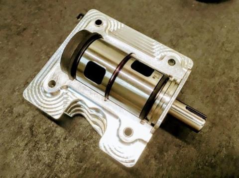
According to Vaztec, it is preferable to characterize it as a simple shaft with a slot cut across its axis, providing a designated flow path. The slot aligns with the port during valve rotation, facilitating gas exchange. Analogous to the conventional poppet valve train, the rotation of the Vaztec valve is synchronized with the crankshaft to initiate appropriate valve timing events [15]. Figure 2 illustrates the exposed dual-port rotary valve integrated with its cylinder head, as prototyped by Vaztec.
Figure 2. Vaztec rotary valve
Benefiting from its port design, the Vaztec rotary valve can achieve a remarkably high discharge coefficient when fully open. The incorporation of the rotary valve, which eliminates a substantial portion of reciprocating motions, has been validated through third-party instrumentation and analysis.
In contrast to many inventors, Vaztec has actively pursued the commercialization of their rotary valve, establishing a facility in North Carolina and making notable strides in the industry. Their latest research indicates a forthcoming pursuit of higher compression ratios and enhancements in the surface-to-volume ratio of the combustion chamber [15]. Currently, Vaztec is collaborating with engine manufacturers to expand the integration of their technology into power sports and, ultimately, automotive production applications, including hybrid systems.
2.4 Coates rotary valve
Dating back to the early 1980s, inventor Coates [16] embarked on his journey to develop the Coates rotary valve, making significant contributions in the early 1990s. Patents associated with the spherical rotary valve assembly, valve seal, and spherical valve were granted in 1990 and 1991. Additionally, Coates [17] obtained a patent related to the rotary valve cooling system in 2001.
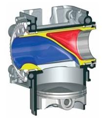
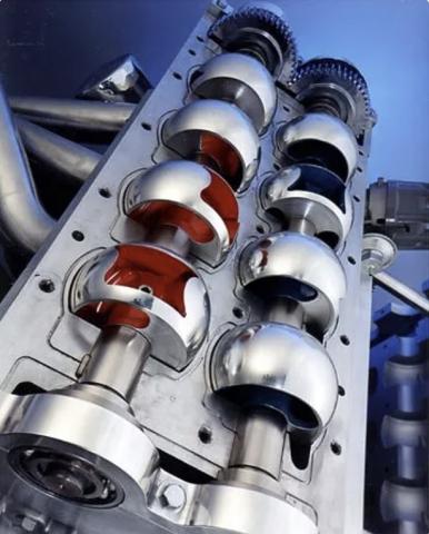
Similar to Vaztec rotary valve, Coates rotary valve is also installed transversely and can be ultimately identified as a shaft with port cut across its axis. However, distinct from the conventional cylindrical shaped simple shaft, the Coates rotary valve features a spherical contact and sealing surface. Figure 3 shows Coates rotary valve spherical surface.
The valve system comprises only two moving shafts, eliminating the need for oil-fed bearings or oil spray. As per Coates, the CSRV engine head operates without the necessity of engine oil presence. Figure 4 shows the cross section of the Coates rotary valve assembly and the bearings.
Figure 3. Coates rotary valve
Figure 4. Coates rotary valve cross section
The continual rotation of the rotary valve serves to dissipate the excess heat accumulated on the valve body during combustion. In contrast to the conventional poppet valve, which remains exposed within the combustion chamber, the rotary valve eliminates the hot spot generated by combustion in the subsequent stroke. This facilitates the incorporation of higher compression ratios in the design of a combustion engine.
2.5 Swinging valve (SwV)
SwV was created and named by Kovács’s team. The valve is considered as a type of rotary valve despite its name. The valve is cylindrical shaped with a large offset cutout in the side. The valve is positioned horizontally and rotates in place. The uniqueness is that instead of spinning continuously, SwV rotates back and forth to open and close the port. Each cylinder is assigned two valves to operate intake and exhaust respectively. Figure 5 presents the layout of swinging valve [18].
Figure 5. Layout of swinging valve
2.6 Hofmann valve
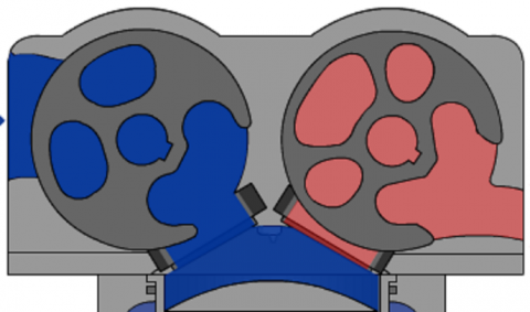
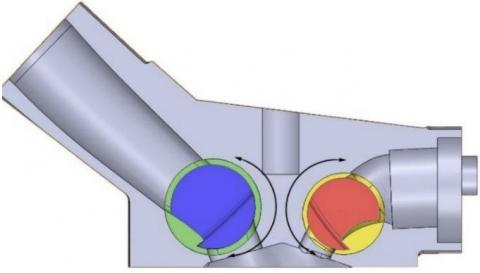
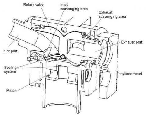
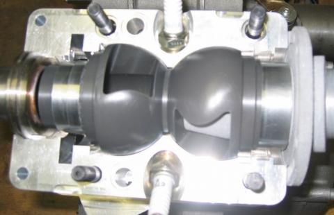
Proposed by Hofmann-Drehschiebermotoren in 2012, Hofmann valve was fully developed and manufactured. The valve is shaped into two linked spheres with each sphere functions as a valve. Each sphere has a unique shaped through cutout in the side functions as the valve port opening. The valve is driven by conventional timing chain or timing belt and operate under a fixed timing. According to the inventor, Hofmann valve offers possibility for 20-50% less package and 20-60% less weight on the cylinder head. The rotary valve scavenging areas are equal if not superior to modern poppet valve cylinder head. Figure 6 shows the cross section of Hofmann valve engine. Figure 7 presents the actual manufactured Hofmann valve [19].
Figure 6. Cross section of Hofmann valve engine
Figure 7. Actual manufactured Hofmann valve
2.7 Camcon Auto IVA
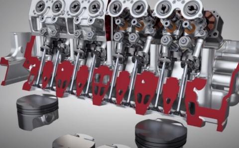
While the previously mentioned systems feature well-designed structures incorporating innovative rotary valves, none of them have the capability to independently control each cylinder. In simpler terms, all the valves remain interconnected through a virtual camshaft. Developed by Camcon Auto and referred to as Intelligent Valve Actuation (IVA), this system eliminates the need for any camshaft and employs a rotary actuator to drive each individual valve. Each valve is equipped with its own IVA actuator, which allows for the instantaneous adjustment of valve timing, duration, or lift.
Figure 8. Camcon Auto IVA
According to Camcon Auto's demonstration, IVA can execute a full cycle of valve events or perform a half valve event and revert. This flexibility allows IVA to adapt valve lift, timing, and duration more freely, contributing to emission control under varying working conditions.
However, it's crucial to note that fundamentally, IVA still operates on a conventional poppet valve, inheriting the disadvantages associated with poppet valves. Despite this, Camcon Auto asserts the integration of a built-in fail-safe and automatic protection to prevent the selection of events that pose a risk of valve clash. Figure 8 illustrates a layout featuring multi-cylinder IVA.
From the above literature review, rotary valve history and recent works analysis, a few key features are summarized to present the advantages of the rotary valve. The following Table 1 is created to list the most recent and developed rotary valves. One can clearly identify the key features and make comparison. Notably, despite not being a typical rotary valve configuration, IVA from Camcon Auto also utilize a servo motor driven rotary actuation mechanism, thus included in the table. At the very end of the table, a new proposed rotary valve concept carrying more desirable features is expressed.
Table 1. Rotary valve concepts comparison
|
New Valve Concept |
Vertical Valve |
Camcon Auto IVA |
Hofmann Valve |
Swinging Valve |
Deng’s Double Valve |
Coates Valve |
Vaztec Valve |
Bishop Valve |
Name |
|
2 |
2 |
2 |
1 |
2 |
2 |
2 |
1 |
1 |
Valves per cylinder |
|
2 |
2 |
2 |
2 |
2 |
2 |
2 |
2 |
1 |
Ports per cylinder |
|
Spherical |
Bell shape |
Poppet valve |
Spherical |
Cylindrical |
Cylindrical |
Spherical |
Cylindrical |
Cylindrical |
Valve shape |
|
Variable |
Variable |
Variable |
Fixed |
Fixed |
Fixed |
Fixed |
Fixed |
Fixed |
Timing |
|
Variable |
Variable |
Variable |
Fixed |
Fixed |
Fixed |
Fixed |
Fixed |
Fixed |
Lift |
|
Variable |
Variable |
Variable |
Fixed |
Fixed |
Fixed |
Fixed |
Fixed |
Fixed |
Duration |
|
Natural mechanical seal |
Natural mechanical seal |
Natural mechanical seal |
Natural mechanical seal |
Valve surface seal |
Valve surface seal |
Valve surface seal |
Natural mechanical seal |
Valve surface seal |
Sealing method |
|
Radial through port |
Radial surface port |
Poppet valve port |
Radial through port |
Radial offset cut-out port |
Radial offset cut-out port |
Axial offset port |
Radial through port |
Axial center port |
Entry and exit |
|
Servo motor |
Servo motor |
Servo motor |
Timing belt/chain |
Unknown |
Timing belt/chain |
Timing belt/chain |
Timing belt/chain |
Timing gear set |
Driving mechanism |
|
High |
Low |
High |
High |
High |
High |
High |
High |
High |
Compression ratio |
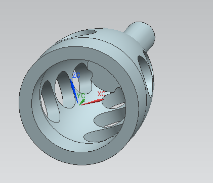
The bell shape rotary valve proposed above carries most preferred features compared to the new concept. However, the inner bell shape halo space in the valve body will create excess combustion chamber volume when both intake and exhaust valves are closed. Since compression ratio is defined as the ratio of the volume of the cylinder and its head space (including the pre-combustion chamber, if present) when the piston is at the bottom of its stroke (BDC) to the volume of the head space when the piston is at the top of its travel (TDC), the excess combustion chamber volume will affect maximum designed compression ratio. In certain engine designs such as diesel engine or compression-ignition gasoline engine, a not high enough compression ratio may become unacceptable. Figure 9 shows the inner space of the bell shape rotary valve.
Moreover, the proposed bell shape rotary valve includes a valve body and a valve housing which is designed to be press fitted into the corresponding cylinder head. Since most of the reviewed rotary valve configurations do not include a valve housing. The valve housing is considered an extra component and the installation procedure may be unnecessary. The outer surface curve of the bell shape valve body and the inner surface curve of the bell shape valve housing remain constant contact and can be classified as a sliding pair. Although the surface curve was created by a section of circle, it is still possible that the valve body and the valve housing experience seizure under certain condition.
Figure 9. Bell shape rotary valve inner space
Ideally, the new proposed concept should preserve two independent rotary valves operating two separate ports for intake and exhaust, respectively. In order to save the variable valve capability, the new proposed design should also be driven by servo motors. The entry and exit ports in the rotary valve are more preferred to be radial through ports, thus the valve can form a natural mechanical seal when it is closed during the combustion stroke. The sliding pair between the valve body surface and the outer surface demands low friction and lower risk of seizure. A spherical shape valve body provides more even and larger contact surface and can prevent axial movement thus is more desirable. In order to create high compression ratio, the valve port interface should not be too far from the combustion chamber. Excess volumes should be minimized to reduce the compression volume.
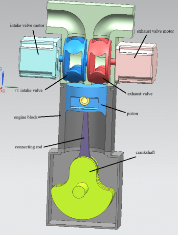
Referencing the above requirements, a new horizontal positioned, servo motor driven, spherical rotary valve configuration is generated for further evaluation. Thus, the valve shape, opening area, timing and efficiency are the primary parameters selected for analysis. Thus, the valve shape, opening area, timing and efficiency are the primary parameters selected for analysis. For geometric model, cylinder bore, piston stroke, displacement volume, crankshaft angle, rod length and throw radius are selected as parameters using standard engine design whereas the thermodynamic model is based on Otto cycle with conventional modeling parameters such as mass fuel ratio, air ratio, volume of cylinder, pressure and temperature. Figure 10 shows the cross section of the new rotary valve layout. In the new design, each valve is driven by its electric servo motor rotating around its center axis. When the spindle shape radial through cut-out is aligned to the opening in the cylinder head, the port is opened. Turning the valve by 45 degrees, the solid section of the valve body will align to the opening in the cylinder head to close the port.
Figure 10. Cross section of the new improved rotary valve layout
4.1 Valve related calculation and validation
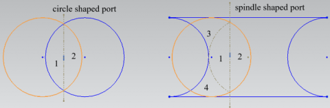
One of the greatest advantages of the rotary valve is that the valve can create its maximum opening area much quicker than the conventional poppet valve. Instead of a circle through cut-out, the port in the new valve is further improved and features a spindle shaped cut-out to maximize the valve efficiency. Figure 11 shows the comparison of the initial opening area between the round port and the spindle shape port.
Figure 11. Comparison of the valve opening between circle port and the spindle port
As seen in Figure 11, the circle valve port opening area can be calculated by the sum of area 1 and area 2, while the spindle shape valve port opening area is assembled by the sum of area 1, area 2, area 3 and area 4, mimicking a moon shape. In other words, with same critical port diameter and valve rotating speed, the spindle shaped port will create opening area faster than the circle port, contributing more mass flowing through the port.
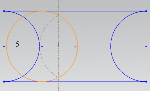
Figure 12. Simplified spindle port problem
Figure 12 is then created to simplify the problem. The valve opening area can be calculated by subtracting the unopened area 5 from the maximum valve opening area.
$A_6=\arccos \left\{\frac{r-\left(r-d_o\right)}{r} r^2-\left(\sqrt{r^2-\left(r-\left(\mathrm{r}-d_o\right)\right)^2}\left(r-\left(r-d_o\right)\right)\right)\right\}$ (1)
The problem can then be solved by the following Eq. (2).
$A_{m o o n}=\pi r^2-2 * A_6$ (2)
4.2 Engine geometrical modeling
The present research will adhere to the use of International Standard Units (SI units) as the standardized system of measurement, ensuring consistency and compatibility with global scientific conventions for accurate and universally recognized data representation.
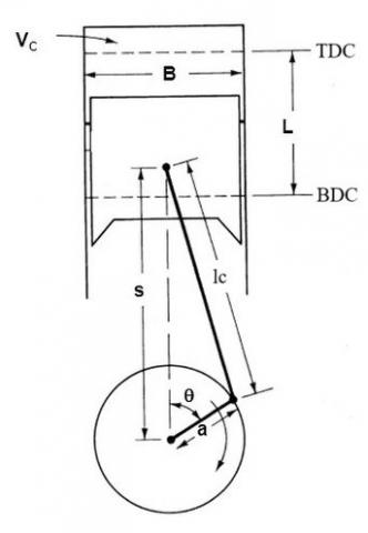
Figure 13. Internal combustion engine geometry
The major geometrical parameters for a reciprocating internal combustion engine are highlighted in Figure 13 and described in introduction section fundamental principles and benchmark engine model. It is still worth mentioning that the unitary cylinder displacement is the volume displaced by the piston traveling from BDC to TDC thus the total cylinder volume is the sum of displacement volume and clearance volume. The modeling parameters are expressed in the following.
Cylinder bore:
$B$ (3)
Piston stroke:
$S$ (4)
The swept volume is usually named as displacement volume:
$V_d=\pi * \mathrm{~S} *\left(\frac{B}{2}\right)^3$ (5)
Clearance volume is calculated from the displacement volume and the stated compression ratio:
$V_c=\frac{V_d}{r_c-1}$ (6)
While the actual compression ratio is more important in the computation, it is defined by the ratio between the actual cylinder volume and the clearance volume:
$r_{c t}=\frac{V_d+V_c}{V_c}$ (7)
The cylinder volume equation can be defined from analyzing the cylinder geometrical parameters.
$\frac{\mathrm{dV}}{\mathrm{d} \theta}=\frac{V_d}{2}\left[1+\frac{L_c}{a}-\cos \theta-\sqrt{\left(\frac{L_c}{a}\right)^2-\sin ^2 \theta}\right]$ (8)
where,
$\theta$ is crankshaft angle,
$L_c$ is connecting rod length,
$a$ is crank throw radius.
4.3 Engine thermodynamic modeling
In the realm of ICE, the Otto cycle stands as a fundamental framework for understanding the thermodynamic processes that drive spark-ignition engines, commonly employed in gasoline-powered vehicles. Developed by Nikolaus Otto in 1867, this theoretical cycle delineates the engine's operation through four distinct phases: isentropic compression, constant volume heat addition, isentropic expansion, and constant volume heat rejection. As an idealized representation, the Otto cycle serves as a cornerstone for engine simulation studies, providing insights into theoretical performance and efficiency. By comprehensively exploring the cyclic interplay between compression, combustion, expansion, and exhaust processes, researchers can gain valuable insights into the intricate dynamics of ICE and optimize their designs for enhanced performance and reduced environmental impact. Referencing a typical Otto cycle curve in Figure 14, the four processes are expressed as the following.
Figure 14. Typical Otto cycle curve
Process 1-2: Isentropic Compression
This process represents the compression stroke in the Otto cycle.
The air-fuel mixture is compressed adiabatically (without heat exchange with the surroundings) by the upward movement of the piston.
The compression process is isentropic, meaning it occurs with constant entropy.
As the volume decreases, the pressure and temperature of the air-fuel mixture increase.
$P_1=P_6=P_0$ (9)
$V_1=V_t=V_d+V_c$ (10)
$T_1=T_0$ (11)
$w_{61}=\left(V_1-V_6\right) P_0$ (12)
$m_m=\frac{P_1 V_1}{T_1 R}$ (13)
where,
$V_t$ represents total cylinder volume,
$w_{61}$ defines the intake work,
$m_m$ defines the mass of fluid inside the cylinder,
R represents universal real gas constant.
The intake temperature $T_1$ is assumed to have a small enough change than the surround temperature $T_0$.
Process 2-3: Constant Volume Heat Addition
This process corresponds to the combustion or power stroke in the Otto cycle.
After the compression, a spark plug ignites the compressed air-fuel mixture, leading to rapid combustion.
The combustion occurs at constant volume, which is an idealized assumption for spark-ignition engines.
The heat released during combustion increases the pressure and temperature of the gas.
$P_2=P_1\left(r_{c t}\right)^\gamma$ (14)
$V_2=V_c$ (15)
$T_2=T_1\left(r_c\right)^{\gamma-1}$ (16)
$w_{12}=c_v\left(T_1-T_2\right)$ (17)
$V_3=V_C$ (18)
$Q_{23}=Q_{i n}=m_f Q_{H V} \eta_{c o m b}=m_m c_p\left(T_3-T_2\right)$ (19)
$P_3=\left(\frac{T_3}{T_2}\right) P_2$ (20)
where,
$c_v$ is the specific heat at constant volume,
$\gamma$ is the ratio of specific heat,
$m_f$ is the mass of fuel,
$m_a$ is the mass of air,
$Q_{H V}$ is the heat value of fuel,
$\eta_{c o m b}$ is the combustion efficiency,
Process 3-4: Isentropic Expansion
This process represents the expansion stroke in the Otto cycle.
The high-pressure, high-temperature gas undergoes adiabatic expansion as the piston moves downward.
Similar to the compression process, the expansion process is isentropic, with a decrease in pressure and temperature as the volume increases.
$P_4=P_3\left(\frac{1}{r_c}\right)^\gamma$ (21)
$V_4=V_t$ (22)
$T_4=T_3\left(\frac{1}{r_c}\right)^{\gamma-1}$ (23)
$w_{34}=c_v\left(T_3-T_4\right)$ (24)
Process 4-5: Constant Volume Heat Rejection
This process corresponds to the exhaust stroke in the Otto cycle.
The exhaust valve opens, and the burned gases are expelled from the cylinder.
Heat is rejected from the system at constant volume, representing the idealized assumption that the exhaust gases are expelled without further expansion.
As the exhaust gases are removed, the pressure and temperature of the remaining gas decrease.
$P_5=P_0$ (25)
$V_5=V_1$ (26)
$T_5=T_0$ (27)
The net indicated work represents the total power produced within the cylinder over one cycle during the expansion stroke, driven by the gas pressure pushing the piston downwards. It is determined through the thermodynamic cycle of the engine, factoring in the losses attributed to heat transfer across the control volume. With all thermodynamic states defined, the indicated work is derivable as the disparity between the work produced in the power stroke and that expended during the compression stroke. The indicated power is consequently characterized as a function of crankshaft revolution and the number of revolutions per power stroke. In this investigation, the engine under consideration operates on a four-stroke cycle, thus the number of revolutions per power stroke is 2.
$W_{n i}=w_{34}-w_{12}$ (28)
$W_i=W_{n i}\left(\frac{N}{n}\right)$ (29)
where,
$W_{n i}$ is net indicated power,
$W_i$ is indicated power.
The thermal efficiency is related to compression ratio.
$\eta_t=1-\left(\frac{1}{r_c}\right)^{\gamma-1}$ (30)
Brake power represents the power effectively delivered by the engine, accounting for mechanical losses incurred during operation. It encompasses the inefficiencies inherent in the engine's mechanical system. The relationship between brake power and indicated power is mediated by mechanical efficiency, a factor heavily contingent upon the design of the engine.
$\eta_m=\frac{W_b}{W_i}$ (31)
From an approach done by Pulkrabek in 2004, an equation extracted from graphical curve fitting appropriately describe the mechanical efficiency.
$\eta_m=-0.061 \bar{U}_p^2-1.441 \bar{U}_p+92.62$ (32)
$\bar{U}_p=2 * S * N$ (33)
$\mathrm{bsfc}=\frac{m_f}{W_h}$ (34)
$\tau=\frac{W_b}{2 \pi N}$ (35)
$\mathrm{bmep}=\frac{W_b n}{V_d N}$ (36)
where,
$\bar{U}_p$ is average piston speed,
$\tau$ is torque,
$\mathrm{bsfc}$ is brake specific fuel consumption,
$\mathrm{bmep}$ is brake mean effective pressure.
The more flowing into the cylinder means more fuel can be converted into work. To increase the flow, volumetric efficiency is the one to be optimized.
The total mass aspirated into the cylinder is defined as the integral of mass flow rate, for the intake valve, from valve opening to valve closing.
$M_{a s}=\int_{V O}^{V C} d m_r$ (37)
where,
$M_{a s}$ is total mass aspirated,
$V O$ stands for valve opening,
$V C$ stands for valve closing,
$m_r$ is mass flow rate.
The volumetric efficiency is suggested as a function mass flow rate.
$\eta_v=\frac{\mathrm{M}}{\rho_I V_d}$ (38)
where,
$\mathrm{M}$ stands for inducted mass,
$\rho_i$ stands for intake density,
$V_d$ stands for the displacement volume.
The mass flow rate equation is described as the following.
$\frac{\mathrm{dM}}{\mathrm{dt}}=\rho_u A_f c_u \sqrt{\left[\frac{2}{\gamma-1}\right]\left[\left(\frac{P_d}{P_u}\right)^{\frac{2}{\gamma}}-\left(\frac{P_d}{P_u}\right)^{\frac{\gamma+1}{\gamma}}\right]}$ (39)
where,
$A_f$ is the effective valve opening area,
$c$ is the speed of sound,
$P_d$ is the downstream pressure,
$P_u$ is upstream pressure,
$\rho_u$ is upstream density.
It is worth mentioning that the upstream condition and the downstream condition are relative. For the intake valve, the in cylinder space is the downstream while for the exhaust valve, the in cylinder space is the upstream.
Under the condition where the difference between upstream pressure and downstream pressure is too great, a sonic velocity chock flow can occur. The chock flow condition is described as the following ratio.
$\frac{P_u}{P_d}=\left(\frac{\gamma+1}{2}\right)^{\frac{\gamma}{\gamma-1}}$ (40)
The mass flow rate under chocked flow condition is expressed as the following Eq. (41).
$\frac{\mathrm{dM}}{\mathrm{dt}}=\rho_u A_f c_u\left(\frac{2}{\gamma+1}\right)^{\frac{\gamma+1}{2(\gamma-1)}}$ (41)
The flow coefficient is needed to define the effective valve opening area.
$A_f=C_f A_c$ (42)
where,
$C_f$ is flow coefficient,
$A_c$ is the actual valve opening area.
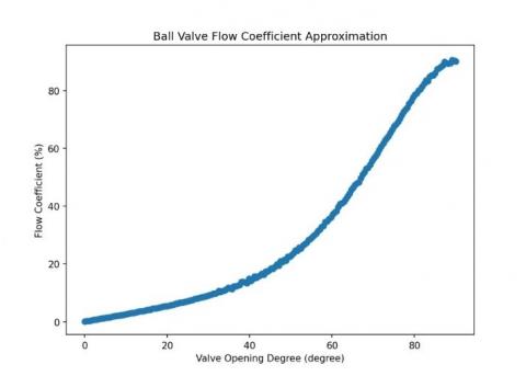
Unlike the bell shaped rotary valve discussed above that can be simplified and treated as “orifice, corner taps”, the new spherical rotary valve imitates a “full port ball valve”. An approximation is applied to the experimental data of the ball valve flow coefficient found in the table from MyDatabook [20]. Since the new spherical rotary valve design has an intake valve opening port of 28mm and an exhaust valve opening port of 26mm, the size difference is considered minimal and can be neglected. Figure 15 shows the approximation curve. The fitted flow coefficient equation is expressed as the following.
$\begin{gathered}C_f=-1.389 * 10^{-9} x^6+2.353 * 10^{-7} x^5-1.225 * 10^{-5} x^4+0.0003316 x^3 \\ -0.002754 x^2+0.2592 x+0.07972\end{gathered}$ (43)
where,
$x$ is the valve position angle.
Figure 15. Ball valve flow coefficient approximation curve 6-degree
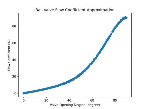
The data obtained from the database is the flow coefficient at each opening degree angle of a full port ball valve and the dataset is linearly organized. Cross-validation divides the dataset into k folds and uses k-1 folds to perform the prediction and then test the outcome with the leftover test fold. Doing so, breaks the consistency of the linear dataset. In this study, random sampling approach is attempted to protect dataset consistency. Instead of dividing the dataset into k folds, the random sampling takes 20% of data from random indices to form the test set while leaving the 80% remaining to be fitting set. Figure 16 shows an example of cross-validation on 6-degree approximation.
Figure 16. Ball valve flow coefficient approximation cross-validation 6-degree
Table 2. 5-degree polynomial approximation cross-validation result
|
No. of Run |
Mean Squared Error |
Total Mean Squared Error |
Total Mean Squared Error Standard Deviation |
|
1 |
0.1038 |
1.3485 |
1.3919 |
|
2 |
0.0824 |
||
|
3 |
3.6728 |
||
|
4 |
2.2184 |
||
|
5 |
0.2620 |
||
|
6 |
0.1553 |
||
|
7 |
0.7025 |
||
|
8 |
3.2886 |
||
|
9 |
0.2281 |
||
|
10 |
2.7706 |
Table 3. 6-degree polynomial approximation cross-validation result
|
No. of Run |
Mean Squared Error |
Total Mean Squared Error |
Total Mean Squared Error Standard Deviation |
|
1 |
0.4385 |
0.1914 |
0.2532 |
|
2 |
0.0703 |
||
|
3 |
0.0690 |
||
|
4 |
0.0373 |
||
|
5 |
0.8555 |
||
|
6 |
0.0790 |
||
|
7 |
0.0429 |
||
|
8 |
0.0568 |
||
|
9 |
0.2470 |
||
|
10 |
0.0176 |
The cross-validation runs 10 times with each group testing data passing into the outcome for validation. Results are shown in Table 2 and Table 3.
6-degree approximation result is selected for future evaluation.
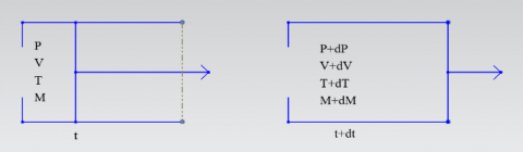
During the process of intake and exhaust, the open system equation is used to determine the cylinder properties. Figure 17 shows the diagram of an open system.
Figure 17. Gas open system diagram
The heat transfer during intake process is assumed to be small enough to be neglected. For the inward flow, the energy equation of the internal energy difference of the cylinder contents between two states can be expressed as the following.
$\mathrm{dE}=\mathrm{dH}-\mathrm{PdV}$ (44)
$\mathrm{dE}=C_v d(M T)$ (45)
The energy of the mass flows into the cylinder is defined as the following.
$\mathrm{dH}=C_p T_a d \mathrm{M}$ (46)
where,
$T_a$ is air temperature,
$C_p$ is the specific heat for gas in constant pressure process,
$C_v$ is the specific heat for gas in constant volume process.
Combine Eqs. (43), (44), (45) and replace the cylinder mass and temperature variation with pressure and volume variation, the equation in the following can be assembled.
$C_v d\left(\frac{P V}{R_s}\right)=C_p T_a d M-P d V$ (47)
where,
$R_s$ is the mass specific gas constant of the cylinder contents.
The constant pressure specific heat is related to the constant volume value by:
$C_p=C_v+R$ (48)
The ratio of the specific heats is:
$\gamma=\frac{C_p}{C_v}$ (49)
where, for air:
$C_v$ is 20.8,
$\gamma$ is 1.4.
Eq. (46) can then be reformed as the following,
$\mathrm{VdP}+\frac{R_s}{20.8} \mathrm{PdV}=R_s \gamma T_a d M$ (50)
Eqs. (39) and (41) can be converted to crankshaft position angle related as the following.
For the normal mass flow:
$\frac{\mathrm{dM}}{\mathrm{d} \theta}=\frac{\rho_u A_f c_u}{\omega} \sqrt{\frac{2}{\gamma-1}\left[\left(\frac{P_d}{P_u}\right)^{\frac{2}{\gamma}}-\left(\frac{P_d}{P_u}\right)^{\frac{\gamma+1}{\gamma}}\right]}$ (51)
For the chocked flow:
$\frac{\mathrm{dM}}{\mathrm{d} \theta}=\frac{\rho_u A_f c_u}{\omega}\left(\frac{2}{\gamma-1}\right)^{\frac{\gamma+1}{2(\gamma-1)}}$ (52)
where,
$\omega$ is engine angular velocity.
Four cases can occur during the engine gas exchange process. They are normal inward flow, normal outward flow, chocked inward flow and chocked outward flow.
In this study, the simulation is built up on standard Otto cycle, thus valve overlapping condition is not considered. For intake process, the final energy equation is assembled as the following.
$\frac{\mathrm{dP}}{\mathrm{d} \theta}=-\frac{R_s \gamma P}{V} \frac{d V}{d \theta}+\frac{R_s \gamma C_1}{V} \frac{d M_i}{d \theta}$
where,
$C_1=T_i$ in this case, we assume $T_i=T_a$ the atmosphere temperature,
$P$ is the initial pressure, in this case, the pressure at the beginning of the intake stroke is $P_a$, the atmosphere pressure,
$V$ is the initial volume, in this case, $v_c$ the clearance volume,
$\frac{{dV}}{{d} \theta}$ is replaced by Eq. (8).
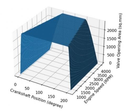
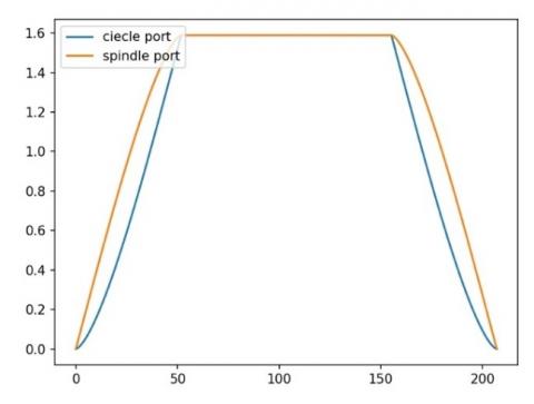
Figure 18 shows the 3D plot of the valve opening area calculation for the spherical shaped rotary valve with spindle shaped valve port. The maximum valve opening area reaches up to 0.954 sq.in. which is bigger than the previous vertical bell rotary valve’s 0.795 [1]. This corresponds to 20% improvement in the opening area. It may not be very obvious for lower engine speed working condition. However, while the engine runs faster, one can easily identify that the spindle shaped port gains valve opening area much more aggressively comparing to the circle shaped port. Up to 3% more volumetric efficiency gain is calculated during the valve opening process benefiting from the spindle shape port. Figure 19 shows the valve opening area curve comparison between the spindle shaped port and circle shaped port under 4000 rpm. Although the maximum valve opening area remains the same for both port designs, one can easily point out that the spindle shaped valve port opens more harshly and creates larger opening area at any point before the completion of the maximum opening area. Correspondingly, the spindle shaped port gains volumetric efficiency much quicker too.
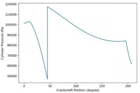
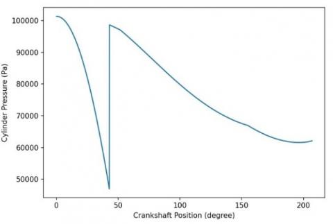
Figure 20 and Figure 21 show the cylinder pressure curve during the intake process under 2500 rpm and 4000 rpm. Differ from conventional poppet valve which causes the cylinder pressure to drop drastically and recover in the late stage of intake stroke, the improved poppet valve generates a unique curve due to its motion property. In the beginning of the intake process, the piston departures from TDC and the rotary valve starts to open. At the moment, the valve opening area is small enough to generate higher vacuum in the cylinder causing choked flow and the cylinder pressure decreases quickly. Soon after, as the piston moving down, the rotary valve gains valve opening area aggressively and balances the intake pressure and the cylinder pressure. Choked flow stops and the flow property becomes normal. Cylinder pressure increases to a much higher level. With the piston moving past half of the stroke, the piston velocity reaches its maximum. Although the rotary valve is fully open, due to higher piston speed, the cylinder pressure sees some losses. Then in the final stage of the intake stroke, the valve starts to close, the piston slows down as it is approaching BDC. Cylinder pressure experiences another decrease. It is also obvious that under a lower engine speed, the cylinder pressure change is smaller, which shows consistency comparing to the reality.
Figure 18. Spherical rotary valve opening area 3D plot
Figure 19. Valve opening area comparison between spindle and circle port under 4000 RPM
Figure 20. Cylinder pressure curve during intake process under 2500 RPM
Figure 21. Cylinder pressure curve during intake process under 4000 RPM
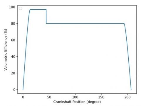
Figure 22 shows the volumetric efficiency for the spindle shaped port at 2500 rpm. The efficiency curve remains consistent throughout the crankshaft position for lower engine speeds. Unlike the conventional poppet valve, which struggles during choked flow processes, the improved rotary valve can achieve greater efficiency by capitalizing on its rapid opening motion. By maintaining the valve position angle, the improved rotary valve enables the volumetric efficiency to remain at its maximum for a significantly extended duration compared to conventional valves.
Figure 22. Volumetric efficiency for the spindle shaped port at 2500 RPM
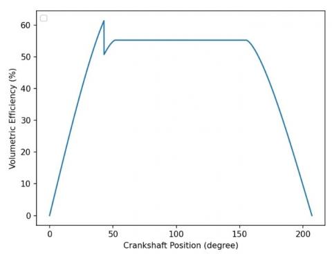
Figure 23. Volumetric efficiency for the spindle shaped port at 4000 RPM
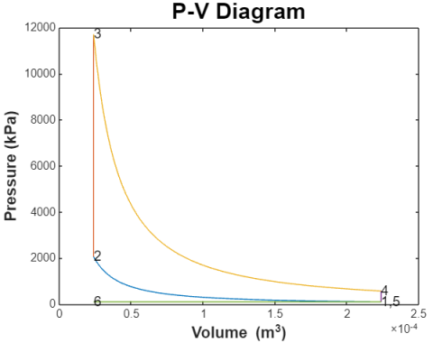
Figure 24. P-V diagram of the engine under 4000 RPM
Figure 23 shows the volumetric efficiency of the improved valve at 4000 rpm. With higher engine speed, the maximum efficiency valve position duration is shorter. The maximum volumetric efficiency also decreases as expected.
Figure 24 shows the P-V diagram of the engine while running under 4000 rpm. The simulated engine model carries over the parameters from the benchmark engine which is a single cylinder engine with only 200 cc of displacement. Contributed by the rotary valve being able to stay in the maximum volumetric efficiency for much longer period, the intake stroke negative work is minimal, indicated by process 6-1 in the figure. A thermal efficiency of 0.54354 was calculated based on compression ratio, valve timing as shown in Figure 24.
The proposed new engine design, featuring an enhanced spherical rotary valve, has been deemed feasible and has demonstrated superior performance compared to conventional poppet valves. This design streamlines the construction of the engine cylinder head and optimizes both the shape of the rotary valve body and the ports. The novel spindle-shaped port is validated to perform better than the conventional circle port with up to 3% volumetric efficiency gain during the valve opening process. The maximum valve opening area created by the new spherical rotary valve is 0.954 sq.in. which is 20% larger than the previously reported bell-shape rotary valve’s 0.795 sq.in. The valve flow coefficient prediction was successfully cross validated, and it accurately described the spherical rotary valve flow property.
In this research, predictions are made regarding in-cylinder pressure and volumetric efficiency, both of which can be explained using engine kinematics and mechanical principles. The resulting P-V diagram from the engine simulation provides brief evidence that the rapid opening feature of the new rotary valve greatly reduces negative work. It is demonstrated that the improved spherical shaped rotary valve with spindle port performs better than a conventional poppet valve for engine speeds below 4000 rpm which is a typical range of rpm for personal and commercial vehicles. Authors believe that this research can help to understand new valve designs and their impact on engine performance – mechanical and thermal efficiency and improved flow characteristics.
From an environmental perspective, the new engine design has removed most of the valvetrain components, resulting in a more minimalist engine construction. With fewer parts, there is a reduced environmental impact associated with manufacturing, transporting, distributing, storing, recycling, and disposing of these parts. Additionally, having fewer components reduces internal friction, which enhances mechanical efficiency and decreases friction loss. Improved volumetric efficiency allows the engine to breathe better, thereby reducing pumping losses.
7.1 Experimental valve flow coefficient
Engine valve flow coefficients are crucial for characterizing the performance of valve and port designs, as well as for modeling gas exchange in 0D/1D engine simulations. These coefficients are typically measured under small pressure ratios and ambient air conditions. However, engine operation involves a much broader range of pressure ratios, pressures, and temperatures. In this study, the rotary valve was simplified to a "full port ball valve," closely resembling real-world conditions. Experimental data were selected, and a polynomial approximation method was used to predict the valve flow coefficient, which was then cross-validated using the root mean square error method. A minor difference in valve size was disregarded during the prediction. While these assumptions made the study more manageable and accessible, further refinement is possible. For more precise investigation and validation, 3D Computational Fluid Dynamics (CFD) modeling and simulations could be employed. Additionally, conducting a flow bench test with a 3D-printed rotary valve could provide real-world data for more accurate approximations.
7.2 Variable valve timing
Similar to the Camcon Auto IVA, which is driven by an electric servo motor, the proposed rotary valve in this research can adjust timing, lift, and duration. Here, "lift" refers to the valve opening area. The servo motor can initiate the valve opening process at any point in the crankshaft angle, allowing for variable timing. The system also supports variable duration by adjusting the valve closing process. At lower engine speeds and loads, the servo motor can reverse the valve and begin closing before reaching the maximum valve opening area, resulting in a variable lift system. Simulations and predictions can be conducted to validate this theory.
[1] Dong, W., Bedekar, V.N. (2024). Design, modeling, and feasibility analysis of rotary valve for internal combustion engine. Journal of Combustion, 2024: 8049436. https://doi.org/10.1155/2024/8049436
[2] Padeanu, A. (2023). VW group not abandoning ICE, puts skoda in charge of small engine development. https://www.motor1.com/news/662705/skoda-developing-ea211-engine/.
[3] Hogan, M. (2021). Volkswagen will also stop developing internal combustion engines. https://www.roadandtrack.com/news/a35901171/volkswagen-will-also-stop-developing-internal-combustion-engines/.
[4] Waldersee, V. (2024). Mercedes-Benz delays electrification goal, beefs up combustion engine line-up. https://www.reuters.com/business/autos-transportation/mercedes-benz-hits-cars-returns-forecast-inflation-supply-chain-costs-bite-2024-02-22/.
[5] Ewing, J. (2021). Mercedes-Benz will shift its focus to electric vehicles by 2025. https://www.nytimes.com/2021/07/22/business/mercedes-benz-electric-vehicles.html.
[6] Pandolfo, C. (2024). Mercedes-Benz delays EV goals because of weak demand, will continue to build gas-powered cars. https://www.foxbusiness.com/fox-news-auto/mercedes-benz-delays-ev-goals-weak-demand-continue-gas-powered-cars.
[7] Rosevear, J. (2023). Ford will postpone about $12 billion in EV investment as buyers become more cautious. https://www.cnbc.com/2023/10/26/ford-will-postpone-about-12-billion-in-ev-investment.html.
[8] Valdes-Dapena, P., Isidore C. (2024). Ford is cutting back F-150 Lightning electric truck production. https://www.cnn.com/2024/01/19/business/ford-trimming-ev-pickup-production/index.html.
[9] Mason, B., Lawes, K., Hirakawa, K. (2022). Rotary valve 4-stroke engines for general purpose power equipment and unmanned systems. NPT2022-028. https://www.unmannedsystemstechnology.com/wp-content/uploads/2022/11/Rotary-Valve-4-Stroke-Engines-for-General-Purpose-Power-Equipment-and-Unmanned-Systems.pdf.
[10] Robinson, A.C., Garrett, N.H., Vaseleniuck, D., Uddin, M. (2022). A computational fluid dynamics investigation comparing the performance of an alternative valvetrain design against a traditional poppet valvetrain. ASME Open Journal of Engineering, 1: 011028. https://doi.org/10.1115/1.4054966
[11] Bari, S., Hossain, S.N., Saad, I. (2020). A review on improving airflow characteristics inside the combustion chamber of CI engines to improve the performance with higher viscous biofuels. Fuel, 264: 116769. https://doi.org/10.1016/j.fuel.2019.116769
[12] Nakano, H. (2023). Combustion chamber shape optimization for small diesel engines by coupling CFD and AI. Mitsubishi Heavy Industries Technical Review, 60(2): 1-6.
[13] Waghmare, M.T.S., Lande, B. (2022). A cycle simulation model of a diesel engine for predicting the performance using Python. International Journal of Scientific Research & Engineering Trends, 8(2): 937-944.
[14] Patents for F01L 7 - Rotary or oscillatory slide-valve gear or valve arrangements (1,661). https://www.google.com/patents/sitemap/en/Sitemap/F01/F01L/F01L_7_15.html.
[15] Garrett, N.H., Uddin, M., Bergman, M., Purvis, G., Vaseleniuck, D., Cordier, D. (2022). Development of a rotary valve engine for handheld equipment. SAE Technical Paper. https://doi.org/10.4271/2022-32-0028
[16] Coates, G.J. 2024. Reference. http://www.georgejcoates.com/references.
[17] International, C. Patents. 2024. https://www.coatesengine.com/patents.html.
[18] Kovács, L., Bolló, B., Szabó, S. (2024). A complex comparatrive study of two dissimilar engine valve constructions, for the in-cylinder flow behaviour of a high speed, IC engine. Acta Polytechnica Hungarica, 21(4): 69-86.
[19] Hofmann-Drehschiebermotoren. (2017). Rotary valve engines, designed by Hofmann-Drehschiebermotoren. https://www.hofmann-dsm.com/products/rotary-valve/.
[20] MyDatabook. (2024). Flow coefficient, opening and closure curves of full bore ball valves. https://www.mydatabook.org/fluid-mechanics/flow-coefficient-opening-and-closure-curves-of-full-bore-ball-valves/.