Nehila Tarek*![]() | Benachour Elhadj
| Benachour Elhadj![]() | Hasnat Mohammed
| Hasnat Mohammed![]() | Asnoune Khadidja
| Asnoune Khadidja![]()
© 2023 IIETA. This article is published by IIETA and is licensed under the CC BY 4.0 license (http://creativecommons.org/licenses/by/4.0/).
OPEN ACCESS
This study presents a numerical exploration into the phenomenon of natural convection within a cavity, characterized by a straight (cold) right wall and a wavy (hot) left wall. The focus lies in the dynamic interaction between the working fluid (air) and a sinusoidally moving solid structure (the fin). The Arbitrary Lagrangian-Eulerian (ALE) methodology is employed to handle the moving mesh, and the Galerkin weighted residual finite element method is utilized to solve the nonlinear equations and boundary conditions. A mesh validation test is undertaken, and a comparative analysis against numerical reference is included. In a novel approach, a mathematical formulation incorporating the geometric aspect ratio Ar (defined as the fundamental wavelength relative to its wavy width) is introduced into the fundamental equations. Numerical results, including isotherms, streamlines, temperature profiles, horizontal velocity, and local heat flux coefficient, are presented under specific conditions: a geometry ratio Ar=0.3, a Rayleigh number spanning from 103 to 107, and a dimensionless time t ranging from 10-5 to 3. These results are based on three distinct positions of the oscillating elastic. The findings elucidate the combined effect of convection and the vibration of the flexible oscillating fin, particularly at high Rayleigh numbers. This study contributes novel insights into the complex interplay between fluid dynamics and vibrating structures in the context of natural convection.
numerical simulations, fluid-structure interaction, natural convection FSI effects, geometry ratio, finite element modeling, corrugated geometry
Fluid-structure interactions (FSIs) pose significant challenges across various contexts due to the complexities inherent in the interaction between fluid flow and moving or deformable structures. Notable examples include the turbulence experienced by an aircraft, the fluid boundary alterations by a butterfly valve, and the sound propagation effects caused by a speaker cone. The ramifications of FSIs are far reaching, with manifestations in diverse fields such as engine combustion chambers [1, 2], natural gas transmission [3-7], robotics, particularly surgical robotics [8-11], civil engineering [12-16], aerospace engineering [17-20], hydraulics [21], topology [22], ocean engineering [23, 24], biomechanics [25-27], nuclear engineering [28], and even food processing [29].
The interaction between fluid flow and a solid structure typically results in pressure and temperature loads on the structure. Such interactions can induce significant deformations that, in turn, modify the fluid flow. The complexity of the FSI phenomena necessitates the application of multiple approaches for their investigation, including numerical simulations [30-32], experimental methods [33-35], and hybrid techniques [36]. Within the extensive body of scientific literature addressing FSI, the moving mesh Arbitrary Lagrangian-Eulerian (ALE) method has been frequently utilized [37, 38] due to its capacity to handle the intricate nature of FSI phenomena. This technique has been applied in both 2D [39, 40] and 3D [41, 42] contexts, providing valuable insights into the dynamic interplay between fluid flow and structural deformations.
The role of fluid-structure interaction (FSI) in natural convection, a pivotal mechanism of heat transfer, is markedly pronounced in cavities outfitted with double-flexible-oscillating fins. This study delves into the influence of FSI on natural convection within a square cavity. A flexible elastic fin, fastened to the base of the cavity, governs the desired aerodynamic behavior and encapsulates the impact of FSI on convection within a uniquely corrugated cavity. The investigation casts light on the consequences of flexible elastic fins in cavities populated by power-law, non-Newtonian fluid flow and heat transfer.
Despite an abundance of existing research, studies addressing natural convection in a wavy cavity, particularly those exploring the interaction between air and a flexible fin, are noticeably lacking. Thus, our study intends to fill this gap by examining the effect of the geometric ratio (Ar) and buoyancy forces on heat transfer. A primary objective of this inquiry is to understand how the presence of an oscillating flexible fin alters the heat flow within the cavity, including potential disturbances in fluid speed and direction. Our findings demonstrated a coupled influence of convection and the vibration of the flexible oscillating fin, an effect that was particularly prominent at high Rayleigh numbers with displacement in the left side of the oscillating fin element. This advanced modeling approach to understanding complex phenomena is a significant contribution, as FSIs are integral to the design of various engineering systems. Ignoring the oscillatory interactions in structures composed of fatigue-prone materials could potentially lead to catastrophic outcomes.
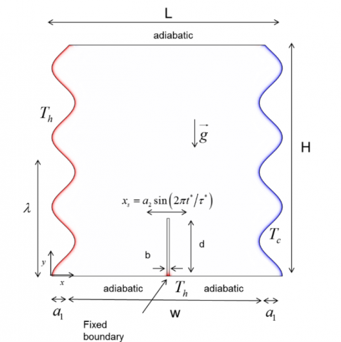
In this study, fully developed heat transfer and fluid flow are numerically simulated in a two-dimensional, vertically-oriented corrugated cavity as illustrated in Figure 1. The cavity's geometry is characterized by a height H and a width w, with a corrugated surface that has a fundamental wavelength denoted by λ and an amplitude denoted by a1.
The profile of the sinusoidal corrugated right and left walls [43] illustrated is defined by:
$\left\{\begin{array}{l}x_r=w-a_1\left[1-\cos \left(2 \pi\left(\frac{y}{\lambda}\right)\right)\right] \\ x_l=a_1\left[1-\cos \left(2 \pi\left(\frac{y}{\lambda}\right)\right)\right]\end{array}\right.$ (1)
In the context of solid dynamics, the behavior of a thin elastic fin of fixed length d and thickness b located in the middle of the lower wall is of particular interest. This fin is known to oscillate in a sinusoidal manner when exposed to a fluid flow, and its motion can be described by the following equation.
$x_s=a_2 \sin \left(\frac{2 \pi t^*}{\tau^*}\right)$ (2)
where, $x_s, t^*, a_2$ present respectively the flexible thin fin movement position, the time and the oscillation in their dimesnonal form. The oscillation frequency is introduced as $1 / \tau^*$. The physical model, as well as the important geometric parameters, are illustrated and detailed in Figure 1.
Figure 1. Physical model and coordinates system
In our study, we focused on the phenomenon of natural convection in the context of the interaction between a fluid (air) and a structure (an elastic fin undergoing sinusoidal motion), within an undulating cavity. This shape was chosen in the engineering design to help us take it into consideration and provide a comparative study with a non-corrugated cavity to clarify the importance and effect of this shape on thermal convection, thus increasing the contact surface area between the working fluid and the hot heat source. The geometric parameter of ripple, denoted by Ar, is introduced into the basic equations for both the solid and the liquid. This allows us to examine the effect of this parameter on the phenomenon in order to optimize convective heat transfer processes inside the cavity.
The fluid within the corrugated cavity is considered to be unsteady, natural convection regime, incompressible, and Newtonian. Temperature fluctuations impact the thermophysical attributes of the fluid, with the Boussinesq approximation employed. This approximation disregards density changes regarding the equation of motion's inertia but retains them in the buoyancy term of the vertical equation. Additionally, it is assumed that all other thermodynamic and transport properties remain unaffected by temperature, and the influences of compressibility and dissipation are deemed insignificant. In fluid-structure interaction and solving the Navier-Stokes formulations are solved in a mobile or deformable domain. Among the approaches used, the Arbitrary Lagrangian-Eulerian (ALE) method arouses much interest [44]. Therefore, we obtain the dimensional equations expressing the mass conservation and momentum (i.e., Navier-Stokes equations), and energy in the ALE description can therefore be rewritten in Chapter 3. With this approach, the mesh movement caused by the fin’s oscillation is robustly taken into account. A proper step of time is selected based on as presented in section 3. This section presents the background required for the proposed formulation for the fluid domain and FSI simulations. They are defined as:
The conservation of mass equation:
$\nabla \cdot \boldsymbol{u}^f=0$ (3)
The momentum equations:
$\rho^f \frac{\partial \boldsymbol{u}^f}{\partial t^*}+\rho^f\left(\boldsymbol{u}^f-\boldsymbol{w}^*\right) \cdot \nabla \boldsymbol{u}^f=\nabla \cdot \boldsymbol{\sigma}^{* f}+\rho^f g_y \beta\left(T-T_C\right)$ (4)
The energy equation:
$\rho^f C_p^f\left[\frac{\partial T}{\partial t^*}+\left(\boldsymbol{u}^f-\boldsymbol{w}^*\right) \cdot \nabla T\right]=k^f \nabla^2 T$ (5)
The fluid properties are the density, specific heat, and thermal conductivity, denoted by $\rho^f, C_p^f$ and $k^f$, respectively. The subscript $f$ represents the fluid. The acceleration due to gravity is denoted by $g_y$, and the coefficient of volumetric thermal expansion is denoted by $\beta$. The term $\rho^f g_y \beta\left(T-T_C\right)$ is referred to as the volume force. In the convective term $\left(u^f-w^*\right)$ identify the variation between the fluid domain velocity $u^f$ and mesh velocity $w^*$ at any given time $t^*$.
In addition, $\sigma^* f$ is the total Cauchy stress tensor which is given by:
$\sigma^{* f}=-p^* \boldsymbol{I}+2 \mu \boldsymbol{T}^{* f}\left(\boldsymbol{u}^f\right), \boldsymbol{T}^{* f}\left(\boldsymbol{u}^f\right)=\frac{1}{2}\left[\nabla \boldsymbol{u}^f+\left(\nabla \boldsymbol{u}^f\right)^T\right]$
where, $\mu$ is the fluid dynamic viscosity, $p^*$ is the dimension of the fluid pressure, $\boldsymbol{I}$ denotes the second-order identity tensor, and $T^{* f}\left(u^f\right)$ present the fluid strain rate tensor.
The dimensional equations of elastodynamic displacement and energy of the fin can be expressed as follows:
$\rho^s \frac{d^2 \boldsymbol{\varphi}^{*_s}}{d t^{*_2}}=\nabla \cdot \sigma^{*_s}+\rho^s g$ (6)
$\rho^s C_p^s \frac{\partial T}{\partial t^*}=k^s \nabla^2 T$ (7)
The density, the specific heat, and the thermal conductivity of the solid are respectively denoted by: $\rho^s, C_p^s$ and $k^s$. S is the solid abbreviation. $\varphi^{* s}$ is the solid displacement vector, $\rho^s g$ is the force applied to the body, and $\mathrm{T}$ denotes fluid/solid temperature, which all are in their dimensional form.
Consider the linear fin to be made of isotropic elastic material, and account for its nonlinear geometry variation under the pressure exertion of the fluid. The stress tensor is therefore represented as:
$\boldsymbol{\sigma}^{* s}=J^{-1} F^* S^* F^{* T}$ (8)
where, $F^*=I+\nabla \varphi^{* S}$ is the gradient tensor of the transformation and $J=\operatorname{det}\left(F^*\right)$ is the determinant of the matrix $F^*$, the second Piola-Kirchhoff tensor $S^*$ is defined by the following equations:
$\varepsilon^*=\frac{1}{2}\left(\nabla \boldsymbol{\varphi}^{*_s}+\nabla \boldsymbol{\varphi}^{*_s T}+\nabla \boldsymbol{\varphi}^{*_s T} \cdot \nabla \boldsymbol{\varphi}^{*_s}\right), S^*=\mathbb{C}\left(E^*, v\right):\left(\varepsilon^*\right)$ (9)
where, $\mathbb{C}\left(E^*, v\right), E^*$ and $v$ are the elasticity tensor, the Young modulus of elasticity, and the Poisson ratio, respectively, the colon ":" is the double-dot tensor product.
Boundary conditions:
The corrugated walls on the right and left of the cavity are maintained at a constant cold temperature Tc and a constant hot temperature Th, respectively. The horizontal walls are thermally insulated. For the fixed part, the fin is maintained at a constant hot temperature Th. Additionally, it was taken into account that the solid and fluid phases are separate and that at the point where the two media come into contact, they interchange energy and momentum. The following premises are made regarding the fluid-solid interface's dynamic and energy-balancing boundary conditions:
$\left\{\begin{array}{l}\left.\frac{\partial \boldsymbol{\varphi}^{* s}}{\partial t^*} \cdot n\right|^s=\left.\boldsymbol{u}^f \cdot n\right|^f \\ \left.\boldsymbol{\sigma}^{{ }^*} \cdot n\right|^s=\left.\left[-p^* \mathbf{I}+\mu\left(\nabla \mathbf{u}^f+\left(\nabla \mathbf{u}^f\right)^T\right)\right] \cdot n\right|^f \\ \left.k^f \nabla T \cdot n\right|^f=\left.k^s \nabla T \cdot n\right|^s\end{array}\right.$ (10)
n: the normal unit vector.
This implies a condition of adhesion for the fluid (equality of velocities), and that the forces on the interface are conserved (equality of stresses).
Dimensionless Form of the governing equations:
The dimensionless variables are listed below.
$\begin{aligned} & X=\frac{x}{w}, Y=\frac{y}{w},(B, \mathrm{D})=\frac{(b, d)}{w},(u, v, \bar{w})=\frac{\left(\boldsymbol{u}^f, \boldsymbol{v}^f, \boldsymbol{w}^*\right) \lambda}{\alpha_f}, \\ & \theta=\frac{\left(T-T_c\right)}{\left(T_h-T_c\right)}, \boldsymbol{\varphi}=\frac{\boldsymbol{\varphi}^{*_s}}{w}, \boldsymbol{\sigma}^s=\frac{\boldsymbol{\sigma}^{*_s}}{E^*}, t=\frac{t^* \alpha_f}{w \lambda}, \\ & \left(\eta_1, \eta_2\right)=\frac{\left(a_1, a_2\right)}{w}, \psi=\frac{\psi^* w \lambda}{\alpha_f}, \tau=\frac{\tau^* \alpha_f}{w \lambda}, P=\frac{\lambda^2 p^*}{\rho^f \alpha_f^2}, \\ & A r=\frac{\lambda}{w}, \boldsymbol{\sigma}^f=\frac{\boldsymbol{\sigma}^{* f} \cdot \lambda^2 w}{\rho^f \alpha_f^2}, \mathrm{~T}^f\left(\mathrm{u}^{\mathrm{f}}\right)=\frac{\mathrm{T}^{f^*}\left(\mathbf{u}^{\mathrm{f}}\right) w^2 \lambda}{\alpha_f}\end{aligned}$ (11)
The use of dimensionless variables from Eq. (11) in all the governing equations of the system gives us new dimensionless formulas presented as follows:
The dimensionless Eq. (1) of the corrugated surface can be expressed by Eq. (12):
$\left\{\begin{array}{l}X_r=1-\eta_1\left[1-\cos \left(2 \pi\left(\frac{Y}{A r}\right)\right)\right] \\ X_l=\eta_1\left[1-\cos \left(2 \pi\left(\frac{Y}{A r}\right)\right)\right]\end{array}\right.$ (12)
where, the dimensionless displacement of the flexible elastic fin presented in Eq. (2) can be expressed as follows:
$X_s=\eta_2 \sin \left(\frac{2 \pi t}{\tau}\right)$ (13)
Consequently, the governing Eqs. (6)-(7) for elastodynamic displacement and temperature of the flexible elastic fin can be expressed as dimensionless:
$\frac{1}{\rho^r} \frac{d^2 \boldsymbol{\varphi}}{d t^2}=E \cdot \nabla^T \boldsymbol{\sigma}^s+E \cdot F_v$ (14)
$\frac{1}{\rho^r} \frac{1}{C_p^r} \frac{\partial \theta}{\partial t}=A r \cdot k^r \nabla^2 \theta$ (15)
where, $\rho^r=\frac{\rho^f}{\rho^s}, C_p^r=\frac{C_p^f}{C_p^s}$, and $K^r=\frac{K^s}{K^f}$ are the parameters ratio for density, specific heat, and thermal conductivity solidliquid, respectively. Thus, $E=\frac{E^* \lambda . w}{\rho^f \alpha_f^2}$ is the flexibility parameter and $F_v=\frac{w\left(\rho^f-\rho^s\right) g}{E^*}$ is the body force source term, both dimensionless.
Presented below are the non-dimensional Eqs. (3)-(5) that elucidate the fluid's dynamic and thermal characteristics within the Arbitrary Lagrangian-Eulerian (ALE) framework:
The conservation of mass equation:
$\nabla \cdot u=0$ (16)
The momentum equations:
$\frac{\partial u}{\partial t}+(u-\bar{w}) \cdot \nabla u=\nabla \boldsymbol{\sigma}^f+\frac{\operatorname{Pr} \cdot \operatorname{Ra}}{A r} \theta$ (17)
The energy equation:
$\frac{\partial \theta}{\partial t}+(u-\bar{w}) \cdot \nabla \theta=A r \cdot K^f \nabla^2 \theta$ (18)
The aforementioned parameters, rendered dimensionless, manifest themselves as follows:
The total Cauchy stress tensor is: $\sigma^f=[-P \mathrm{I}+\mathrm{Pr}$ $\cdot$ $\left.\operatorname{Ar}\left(\nabla u+(\nabla u)^T\right)\right], R a=\frac{g_y \beta\left(T_h-T_c\right) \lambda^3}{v_f \alpha_f}$ is the Rayleigh number, and $\operatorname{Pr}=\frac{v_f}{\alpha_f}$ is the Prandtl number.
Additionally, the visualization of the fluid flow $\psi$ patterns of the dimensionless flow function is defined by solving the following partial differential equation.
$\nabla^2 \psi=\frac{\partial u}{\partial Y}-\frac{\partial v}{\partial X}$ (19)
Taking into account the boundary conditions, the thermal and dynamic behavior of the walls in the dimensionless coordinates is written as:
At the hot wall:
$\left\{\begin{array}{l}X_l=\eta_1\left[1-\cos \left(2 \pi\left(\frac{Y}{A r}\right)\right)\right] \quad 0 \leq \mathrm{Y} \leq(H / w) \\ \mathrm{U}=\mathrm{V}=0, \psi=0, \theta=1\end{array}\right.$ (20)
At the cold wall:
$\left\{\begin{array}{l}X_r=1+\eta_1\left[1+\cos \left(2 \pi\left(\frac{Y}{A r}\right)\right)\right] 0 \leq \mathrm{Y} \leq(H / w) \\ \mathrm{U}=\mathrm{V}=0, \psi=0, \theta=0\end{array}\right.$ (21)
At the upper and lower walls:
$\left\{\begin{array}{l}\eta_1\left[1-\cos \left(2 \pi\left(\frac{Y}{A r}\right)\right)\right] \leq \mathrm{X} \leq 1+\eta_1\left[1+\cos \left(2 \pi\left(\frac{Y}{A r}\right)\right)\right], \mathrm{Y}=(H / w) \\ \mathrm{U}=\mathrm{V}=0, \psi=0, \frac{\partial \theta}{\partial \mathrm{Y}}=0 \\ 0 \leq \mathrm{X} \leq\left(\frac{1}{2}-\frac{B}{2}\right) \text { and }\left(\frac{1}{2}+\frac{B}{2}\right) \leq \mathrm{X} \leq 1, \mathrm{Y}=0 \\ \mathrm{U}=\mathrm{V}=0, \psi=0, \frac{\partial \theta}{\partial \mathrm{Y}}=0\end{array}\right.$ (22)
At the solid embedding
$\left\{\begin{array}{l}\left(\frac{1}{2}-\frac{B}{2}\right) \leq \mathrm{X} \leq\left(\frac{1}{2}+\frac{B}{2}\right) \\ \theta=1\end{array}\right.$ (23)
Hence, the Eq. (10) of the interaction between a solid-fluid can also be expressed in its dimensionless form as follows:
$\left\{\begin{array}{l}\frac{\partial \boldsymbol{\varphi}}{\partial t}=u \\ E^* \boldsymbol{\sigma}^s \cdot n= \\ {\left[-P \mathrm{I}+\operatorname{Pr} \cdot \operatorname{Ar}\left(\nabla \mathrm{u}+(\nabla \mathrm{u})^T\right)\right] \cdot n} \\ \left.\nabla \theta \cdot n\right|^f=\left.k^r \nabla \theta \cdot n\right|^s\end{array}\right.$ (24)
In the present analysis, the parameter of interest is the local heat flux coefficient hc at any point of the hot corrugated wall. This parameter characterizes the efficiency of heat transfer by natural convection. It can be evaluated as follows
$h_c=-\left.A r K^f \frac{\partial \theta}{\partial n}\right|_{\text {near wall }}$ (25)
where, hc is the local heat flux coefficient.
We chose these equations because they often allow us to describe the behavior of the phenomenon of the fluid structure interaction by an approximate resolution, and to propose a better modeling of a single phase of the fluid as is also the case in our situation. The main objective of this equation is to describe the movement of fluids. Since a fluid can be a liquid or a gas, we understand that this equation concerns a whole bunch of things around us. The resolution of these equations modeling a fluid as a continuous medium. In our case we integrate the geometric parameter into this equation in order to treat its influence mathematically and physically.
Among the methodologies employed to address the complex FSI phenomenon, the Arbitrary Lagrangian-Eulerian (ALE) approach stands out as a dependable and precise numerical technique [44-46]. This method effectively captures the movement of mobile structures within the fluid domain. Within the simulation domain, mesh nodes can either adhere to a Lagrangian procedure, remaining stationary, or an Eulerian process, maintaining fixed positions. Alternatively, nodes can follow an arbitrary movement pattern. Comprehensive validation of this method is elaborated [47, 48]. The computational fluid dynamics (CFD) framework draws upon diverse numerical solvers to execute the weighted residual Galerkin finite element method (FEM) [49, 50]. This approach integrates error control, adaptive meshing, and the solution of dimensionless nonlinear equations Eq. (14) to Eq. (18), coupled with boundary conditions Eq. (20) to Eq. (21), as well as the interlinking coupled boundary interface Eq. (24). To discretize the computational domain, non-uniform triangular grid meshes are applied, as illustrated in Figure 2. The computations halt at each time step when the error falls below 10-7, ensuring accurate results.
4.1 Mesh testing
A pivotal factor in enhancing the numerical accuracy of the solution revolves around the selection of an appropriate mesh. To this end, a finer mesh configuration (referred to as "case 2") is strategically employed along the boundary of the heated corrugated wall and the fluid-solid interfaces. The significance of this mesh refinement lies in its ability to capture intricate details with greater fidelity. Figure 2 visually portrays the intricate interplay between the fluid and the fin, offering insights into this interaction.
Figure 2. Constructed mesh of the studied model
In pursuit of this objective, a specialized border meshing technique was meticulously employed along the heated corrugated wall. This technique was executed across four distinct cases, each tailored to maximize precision and accuracy. Detailed information regarding these cases is presented in Table 1, providing a comprehensive delineation of the diverse meshing strategies embraced.
The test scenario is characterized by specific parameter values: t=3, Ra=106, Pr=10, E=1011, and Ar=0.3. These meticulously chosen parameters collectively establish a consistent and controlled foundation for assessing and comparing the performance of the various meshing approaches.
Table 1. Mesh sensitivity test and details of domain meshes and boundary elements as well as the average heat flux coefficient value for four selected mesh sizes
|
Cases |
Domain Elements |
Boundary Elements |
hc Average |
|
Case 1 |
3472 |
239 |
5,4049 |
|
Case 2 |
5148 |
286 |
5,3946 |
|
Case 3 |
8635 |
398 |
5,3932 |
|
Case 4 |
21213 |
755 |
5,3924 |
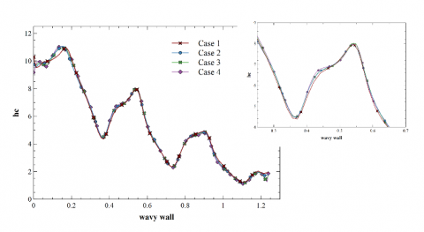
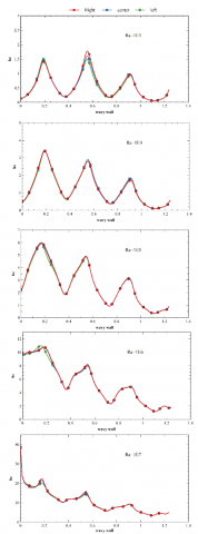
Figure 3. Grid testing of local heat flux coefficient with different grid cases
Figure 3 provides a visual representation of the dimensionless local heat flux coefficient, denoted as "hc". This figure highlights the evolution of hc along the extent of the corrugated wall. Notably, the behavior of hc within Case 2 remains consistent and unaffected by the alteration in mesh type.
It is evident from the analysis that Case 2 stands out as the most suitable and appropriate choice. This conclusion is supported by the fact that the local heat flux coefficient hc within Case 2 remains unaffected by variations in mesh type, reaffirming its reliability and stability (refer to Figure 3). reaffirming its reliability and stability (refer to Figure 3).
4.2 Model validation
In pursuit of refining our numerical approach, we focus on two key aspects: Optimizing computational efficiency and enhancing precision in essential variables' convergence behavior. With this goal in mind, the outcomes of this study are obtained through numerical analysis, utilizing a grid size of 2. These findings are subsequently validated through a comprehensive comparison with previously documented research.
This study places particular emphasis on validating the natural convection phenomenon within a square cavity characterized by a partially heated left wall, a cold right wall, and horizontally thermally insulated walls. To establish the credibility of our results, we undertake a meticulous comparison with the outcomes presented in previous studies [51-53], which delved into the same problem. As a crucial validation measure, we calculate and verify the average Nusselt number test of the heated left wall, a key parameter characterizing heat transfer (refer to Table 2).
Table 2. Comparison results of average Nusselt number validation with literature results for Pr=0.71
|
|
Ra |
||
|
104 |
105 |
106 |
|
|
Ghalambaz and all [51] |
2.2450 |
4.5237 |
8.8663 |
|
Sathiyamoorthy and Chamkha [52] |
2.2530 |
4.5840 |
8.9210 |
|
Val Davis [53] |
2.2430 |
4.5190 |
8.8800 |
|
Present study |
2.2451 |
4.5209 |
8.8253 |
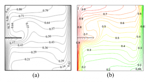
Figure 4. Comparison of the isotherms: (a) Ghalambaz and al. [51], and (b) the present study when t=1.25, Ra=106, Kr=10, E=1011 and Pr =0.7
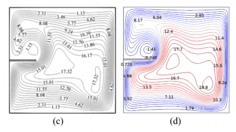
Furthermore, a secondary validation is conducted involving a flexible oscillating fin affixed to the left wall within the square cavity. This validation is executed for specific parameter values: t=1.25, Ra=106, Pr=0.7, E=1011. In this validation, isotherms, depicted in Figure 4, and streamlines, illustrated in Figure 5, are meticulously compared with those presented in reference [51].
By closely examining the results presented in Table 2, Figure 4, and Figure 5, it is evident that a remarkable level of agreement is achieved between our findings and those of the reference study. This robust alignment substantiates the accuracy and reliability of our numerical approach and its ability to capture the intricacies of the physical phenomenon under investigation.
Figure 5. Comparison of the streamlines: (a) Ghalambaz and all [51] and (b) the present study when t=1.25, Ra=106, Kr=10, E=1011 and Pr=0.7
This present study lays the theoretical groundwork for delving deeper into the hydrodynamic and thermic attributes within fluid-structure interaction across diverse multi-domain applications. The comprehensive investigation undertaken here sheds light on the intricate interplay of various coupling factors in the context of natural convection, heat transfer performance, and fluid-structure dynamics. This is achieved within a fluid-structure interaction system, systematically studying the impacts of key parameters.
The factors under scrutiny encompass a spectrum of critical aspects, including the local heat flux coefficient (hc), the variation of velocity (U), temperature profiles (θ), streamlines, and isotherm behaviors. These dynamics are explored across a range of dimensionless times (t) and flexible fin positions within the latter phase.
The study's focus is anchored in air (with Prandtl number Pr=0.7), taking into consideration the non-dimensional fixed parameters of both the fluid flow and solid. Key variables include Rayleigh numbers (Ra) spanning from 103 to 107, a thermal conductivity ratio (Kr) of 10, a geometric ratio (Ar) of 0.3, solid and wall amplitudes (η1 and η2) of 0.1 and 0.05 respectively, Young's modulus (E) at 1011, and specific elastic fin dimensions (B and D) set at 0.01 and 0.25 respectively. The elastic fin's movement period is established at 0.1, forming a comprehensive framework for comprehensive analysis.
5.1 Evolution of fluid and thermal fields
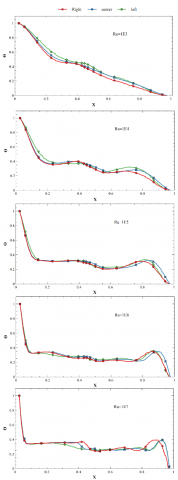
In Figure 6, a detailed examination of the dimensionless temperature distribution is presented for various Rayleigh numbers, while keeping the geometric ratio Ar constant at 0.3, specifically at the position Y=0.25 within the cavity.
A notable observation is made for the case of Ra=103, where heat propagation follows a quasi-linear pattern. Moving away from the intensely heated corrugated wall, and particularly for higher Rayleigh numbers, a gradual decrease in heat intensity is discernible, reaching a value of 0.4. Subsequently, a distinct stabilization of temperature occurs both before and after the region encompassing the limits of the elastic element's vibratory movement.
Figure 6. Variation of temperature profile for different Rayleigh numbers and three fin positions at Y=0.25, Ar=0.3, Kr=10, E=1011, Pr=0.7
Furthermore, at X=0.85, another temperature disturbance emerges. This phenomenon arises due to the proximity of hot air to the cold wall, resulting in a perturbation within the temperature profile (refer to Figure 6).
A significant insight gleaned from the isotherms analysis is the interplay between conduction and convection processes, particularly when considering the influence of varying Rayleigh numbers. At higher Rayleigh numbers, conduction becomes dominant at the upper region of the cavity, whereas convection plays a more significant role at the lower region.
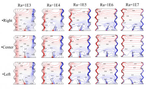
An important observation is the discernible impact of the flexible fin positioned along the middle of the bottom wall. This impact is consistently evident across all cases under investigation. This influence of the fin is further highlighted through the isotherms presented in Figure 7, which underscore the fin's role.
A noteworthy finding is the stability exhibited by the isotherms in later sections of the cavity, regardless of the Rayleigh number (Ra). In contrast, disturbances in the isotherm pattern emerge in the vicinity above the elastic fin, particularly on the left side. This region marks the zone where convection is triggered, leading to an intensification of heat. This phenomenon is more pronounced on the left side of the cavity, as depicted in Figure 7.
Figure 7. Isotherms distributions. for different Rayleigh numbers Ra at Ar=0.3, Kr=10, E=1011 and Pr=0.7
Figure 8. U velocity profile variation for different Rayleigh numbers Ra and elastic fin positions at Y=0.25, Ar=0.3, Kr=10, E=1011, and Pr=0.7
A significant thermal disturbance is evident above the flexible element's fin, attributable to the coupling of conduction and convection effects. This underscores the pivotal role played by fluid-structure interaction in optimizing heat transfer efficiency. The temperature profile demonstrates an inverse relationship with the geometric ratio Ar.
5.2 Ra and Ar effects on Velocity, streamline, and flow distribution
The evolution of horizontal velocity profiles at the designated height of Y=0.25 is illustrated in Figure 8. Through a comparative analysis between fluid flow within a square cavity devoid of undulations and the corrugated cavity with Ar=0.3, a comprehensive understanding of the impact of Ar on convection can be gleaned.
The presence of undulation, as indicated by the Ar=0.3 condition, leads to a pronounced effect on fluid behavior. This undulation contributes to fluid compression, consequently accelerating its motion, particularly evident above the flexible fin element. The fin's motion is itself instrumental in influencing this fluid acceleration.
Furthermore, a direct proportionality between velocity and Rayleigh number becomes evident. For lower Rayleigh numbers, fluid velocity near the side walls remains notably low. However, with increasing Rayleigh numbers, the fluid's velocity experiences a considerable increment, amounting to around 28.33% to 30% for every tenfold increase in Rayleigh number from 103 to 107. This relationship underscores the dynamic influence of Rayleigh numbers on fluid motion within the cavity.
Figure 9 provides a visual representation of the streamlines within the corrugated cavity, showcasing different Rayleigh number values while maintaining Ar=0.3. Several significant observations emerge from this analysis:
Recirculation Zones: For lower Rayleigh numbers, such as Ra=103, a prominent clockwise-rotating recirculation zone is observed above the flexible oscillating fin. This recirculation zone remains consistent regardless of the fin's position. As Rayleigh number increases, this zone extends further.
Figure 9. Streamlines for distributions. for different Rayleigh numbers Ra at Ar=0.3, Kr=10, E=1011, and Pr=0.7
Figure 10. Variation of the local heat coefficient number on the wavy hot wall for different Rayleigh numbers Ra and three fin positions at Ar=0.3, Kr=10, E=1011, and Pr=0.7
Emergence of Additional Recirculation Zone: With Ra=104, a smaller counterclockwise-rotating recirculation zone appears to the left of the elastic fin. This secondary zone is further influenced by the sinusoidal motion of the fin and the presence of the corrugated boundary walls.
Impact of Elastic Fin: The presence of the flexible oscillating fin affixed to the lower wall has a clear impact on the variation in speed across all studied cases. This influence is prominently depicted in the streamline patterns.
The dynamic interplay between fluid motion, fin oscillation, and boundary shapes is vividly captured by the evolving streamline patterns, offering valuable insights into the complex fluid-structure interaction within the cavity.
The corrugated walls and the flexible fin have trapped a part of the fluid and induced local flow circulations at the bottom left region.
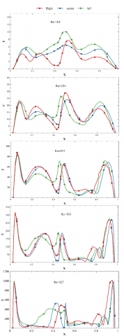
5.3 Ra and Ar effects on local heat flux coefficient
Figure 10 presents a critical parameter of interest: the local heat flux coefficient, which effectively characterizes the heat transfer rate. Several crucial insights can be gleaned from this analysis:
Enhanced Heat Transfer Rate: In the presence of the flexible oscillating fin, the local heat flux coefficient reveals significant heat transfer enhancement. The apex of this enhancement is notably observed in the left area of the cavity. This effect is most prominent in the vicinity of the flexible fin's location.
Impact of Rayleigh Number: As the Rayleigh number (Ra) increases, the heat transfer rate experiences substantial amplification. Specifically, with each transition to a higher Ra value (i.e., Ra=103, 104, 105, 106, and 107), the maximum heat transfer rate doubles. This consistent trend reflects the progressive intensification of heat transfer as the driving force behind the convection phenomenon becomes more pronounced.
Stabilization at High Rayleigh Numbers: A noteworthy observation is the stabilization of the heat transfer system as the Rayleigh number becomes significantly high. This stabilization indicates the convergence of heat transfer processes under the influence of fluid-structure interaction, ultimately leading to a consistent heat transfer rate.
Figure 10 effectively captures the intricate relationship between fluid dynamics, convection, and the presence of the flexible oscillating fin, showcasing how it profoundly influences heat transfer within the cavity.
In Our study, we consider that the Rayleigh number varies between 103 and 107. For values less than Ra=103, the convection phenomenon does not initiate. Conversely, for Ra=107, the flow regime transitions from laminar to turbulent, where the chosen solution method is no longer suitable for this model.
In this study, a comprehensive numerical investigation was conducted to enhance natural convection heat transfer within a wavy cavity by harnessing the influence of a flexible oscillating fin as a flow rate modulator. Air was selected as the working fluid, and the Galerkin finite element method in conjunction with the Arbitrary Lagrangian-Eulerian technique was used for numerical simulations.
The primary objective was to explore the impact of fin flexibility, coupled with dynamic parameters such as amplitude and Rayleigh numbers, on the flow field. The interaction between the geometric ratio and Rayleigh numbers was examined, revealing significant effects on velocity, flow direction, and heat transfer. The Galerkin method facilitated the systematic evaluation of these effects. The most significant findings are summarized below:
• A quasi-linear heat propagation pattern is followed for Ra=103, with a gradual reduction in thermal intensity observed for higher Ra values.
• Discernible impacts on the stability of isotherms are observed in the presence of the flexible fin, with disturbances primarily noted above the fin, mainly on the left side of the cavity.
• Fluid velocity exhibits a direct proportionality with the Rayleigh number, showing a significant increase at higher Ra values.
• Recirculation zones are highlighted by streamlines, which are influenced by the presence of the elastic fin and wavy walls.
• Significant heat transfer enhancement is observed in the presence of the flexible fin, primarily on the left side of the cavity, in terms of the local heat flux coefficient.
• A substantial increase in the heat transfer rate is noted as the Rayleigh number increases.
This study could pave the way for further research, as it is based on the relationship between the geometric ratio (Ar) and the fundamental equations for fluids and solids within various research domains, including nanofluids, porous media, natural convection, and forced convection. This approach has not been explored before.
I would like to thank all reviewers for taking the time and energy to review our work.
I would like to thank the officials of the Directorate General for Scientific Research and Technological Development (DGRSDT) for having included this journal so that Algerian researchers can contribute to the development of their research in this field.
|
$a_1$ |
Amplitude of wavy surface of cavity (m) |
|
$a_2$ |
The fin’s amplitude (m) |
|
b, d |
Thickness and length of the fin (m) |
|
$E^*$ |
Young’s modulus $\left(N / m^2\right)$ |
|
$F^*$ |
The dimensionless transformation gradient tensor |
|
g |
Gravitational acceleration (m / s2) |
|
K |
Thermal conductivity (W / mK) |
|
Ar |
Dimensionless geometry ratio of cavity |
|
W, L |
Width and height of cavity (m) |
|
Pr |
Prandtl number |
|
Ra |
Rayleigh number |
|
$S^*$ |
tensor of stress $\left(N / m^2\right)$ |
|
t |
Non-dimensional time |
|
T |
Temperature (K) |
|
Cp |
specific heat (J / Kg.K) |
|
$\boldsymbol{u}^f, \boldsymbol{v}^f$ |
x- and y- velocity components (m / s) |
|
u, v |
X- and Y- non-dimensional velocity components |
|
P |
Dimensionless Pressure |
|
xr, xL |
Dimensionless equation of the corrugated surface right and left |
|
xs |
The dimensionless displacement of the fin |
|
hc |
Local Heat flux coefficient |
|
$x, y_{\wp} X, Y$ |
Space coordinates $(m) \wp$ Dimensionless space coordinates |
|
Greek symbols |
|
|
$\alpha$ |
Thermal diffusivity (m2 / s) |
|
$\varphi$ |
Dimensionless Deplacement structure |
|
$\beta$ |
Thermal expansion coefficient (1 / K) |
|
$\eta_1$ |
Dimensionless amplitude in wavy surface |
|
$\eta_2$ |
Non-dimensional amplitude of the fin |
|
$\lambda$ |
Frequency of the wavy cavity (m) |
|
$\varepsilon$ |
Strain |
|
$\theta$ |
Dimensionless temperature |
|
$\mu$ |
Dynamic viscosity (Kg / s) |
|
v |
Kinematic viscosity (m2 / s) |
|
$\rho$ |
Density (Kg / m2) |
|
$\sigma^{*_s}$ |
Stress tensor (N / m2) |
|
$\sigma^{*_f}$ |
The total Cauchy stress tensor (N / m2) |
|
$\tau$ |
Dimensionless period of oscillation |
|
$\psi$ |
Non-dimensional stream function |
|
Subscripts |
|
|
c |
Cold |
|
f |
Fluid |
|
h |
Hot |
|
r |
The solid to the fluid property ratio |
[1] Gieras, M., Trzeciak, A. (2023). A new approach to the phenomenon of pulsed combustion. Experimental Thermal and Fluid Science, 144: 110845. https://doi.org/10.1016/j.expthermflusci.2023.110845
[2] Jagadish, V., Anandarao, G., Maddaiah, K.C., Hussain, S., Krishna, V.S. (2023). Design and analysis of gas turbine combustion chamber. In AIP Conference Proceedings, 2492(1): 020031. https://doi.org/10.1063/5.0113361
[3] Lv, W., Zhang, L. (2023). The seismic response of ultra-high voltage gas-insulated transmission lines. Journal of Physics: Conference Series, 2557(1): 012065. https://doi.org/10.1088/1742-6596/2557/1/012065
[4] Ali, W. (2022). Optimal operational analysis of metamodel based single mixed refrigerant cryogenic process for floating liquefied natural gas plant technology. Results in Engineering, 16: 100744. https://doi.org/10.1016/j.rineng.2022.100744
[5] Ma, H., Han, X., Ding, R., Wang, L., Liu, Y. (2023). Study on gas-liquid flow and separation characteristics in the interspace of complex parallel perforated wavy plate deflectors. International Communications in Heat and Mass Transfer, 140: 106498. https://doi.org/10.1016/j.icheatmasstransfer.2022.106498
[6] Karim, M.A., Abdullah, M.Z., Deifalla, A.F., Azab, M., Waqar, A. (2023). An assessment of the processing parameters and application of fibre-reinforced polymers (FRPs) in the petroleum and natural gas industries: A review. Results in Engineering, 18: 101091. https://doi.org/10.1016/j.rineng.2023.101091
[7] Ji, P., Shi, S., Shi, X. (2023). Research on prediction of coal and gas outburst risk based on TIWTD-CNSA. Results in Engineering, 18: 101195. https://doi.org/10.1016/j.rineng.2023.101195
[8] Chella, A., Gaglio, S., Mannone, M., Pilato, G., Seidita, V., Vella, F., Zammuto, S. (2023). Quantum planning for swarm robotics. Robotics and Autonomous Systems, 161: 104362. https://doi.org/10.1016/j.robot.2023.104362
[9] Qiu, S., Kermani, M.R. (2023). Precision fingertip grasp: A human-inspired grasp planning and inverse kinematics approach for integrated arm–hand systems. Robotics and Autonomous Systems, 162: 104348. https://doi.org/10.1016/j.robot.2022.104348
[10] Ahmad, H., Shaul, D.B. (2023). Pediatric colorectal robotic surgery. Seminars in Pediatric Surgery, 32(1): 151259. https://doi.org/10.1016/j.sempedsurg.2023.151259
[11] Liu, Y., Gao, G., Liang, Y., Li, T., Li, T. (2023). Safety and feasibility of robotic surgery for old rectal cancer patients. Updates in Surgery, 75: 1161-1169. https://doi.org/10.1007/s13304-023-01504-9
[12] Yu, C.C., Whittaker, A.S. (2021). Review of analytical studies on seismic fluid-structure interaction of base-supported cylindrical tanks. Engineering Structures, 233: 111589. https://doi.org/10.1016/j.engstruct.2020.111589
[13] Wang, P., Lu, R., Yan, Q., Bao, X., Zhang, J., Liu, L. (2023). The internal substructure method for shock wave input in 2D fluid-structure interaction analysis with unbounded domain using doubly-asymptotic ABC. Mechanics of Advanced Materials and Structures, 30(15): 3111-3124. https://doi.org/10.1080/15376494.2022.2069308
[14] Vadyala, S.R., Betgeri, S.N., Matthews, J.C., Matthews, E. (2022). A review of physics-based machine learning in civil engineering. Results in Engineering, 13: 100316. https://doi.org/10.1016/j.rineng.2021.100316
[15] Du, Z., Liu, G., Huang, X., Xiao, T., Yang, X., He, Y.L. (2023). Numerical studies on a fin-foam composite structure towards improving melting phase change. International Journal of Heat and Mass Transfer, 208: 124076. https://doi.org/10.1016/j.ijheatmasstransfer.2023.124076
[16] Buchwald, J., Kaiser, S., Kolditz, O., Nagel, T. (2021). Improved predictions of thermal fluid pressurization in hydro-thermal models based on consistent incorporation of thermo-mechanical effects in anisotropic porous media. International Journal of Heat and Mass Transfer, 172: 121127. https://doi.org/10.1016/j.ijheatmasstransfer.2021.121127
[17] Bang, C.S., Rana, Z.A., Könözsy, L., Rodriguez, V.M., Temple, C. (2022). Aeroelastic analysis of a single element composite wing in ground effect using fluid–structure interaction. Journal of Fluids Engineering, 144(4): 041202. https://doi.org/10.1115/1.4053089
[18] Ryzhakov, P.B., Marti, J., Dialami, N. (2022). A unified arbitrary Lagrangian–Eulerian model for fluid–structure interaction problems involving flows in flexible channels. Journal of Scientific Computing, 90(3): 85. https://doi.org/10.1007/s10915-021-01748-w
[19] Chu, H.Q., Dinh, C.T. (2023). Aerodynamic and structural performances of a single-stage transonic axial compressor with blade fillet radius. International Journal of Intelligent Unmanned Systems, 11(3): 407-424. https://doi.org/10.1108/IJIUS-07-2021-0069
[20] Benaouali, A., Kachel, S. (2019). Multidisciplinary design optimization of aircraft wing using commercial software integration. Aerospace Science and Technology, 92: 766-776. https://doi.org/10.1016/j.ast.2019.06.040
[21] Souli, M., Aquelet, N. (2011). Fluid structure interaction for hydraulic problems. La Houille Blanche, 97(6): 5-10. https://doi.org/10.1051/lhb/2011054
[22] Bonnet, M., Nski, T.L., Amstutz, S., Henrot, A., Ganghoffer, J.F., Scheid, J.F., Auffray, N. (2021). Synthese de microstructures par optimisation topologique, et optimisation de forme d’un probleme d’interaction fluide-structure. https://hal.science/tel-03598154/.
[23] Khayyer, A., Tsuruta, N., Shimizu, Y., Gotoh, H. (2019). Multi-resolution MPS for incompressible fluid-elastic structure interactions in ocean engineering. Applied Ocean Research, 82: 397-414. https://doi.org/10.1016/j.apor.2018.10.020
[24] Luo, M., Khayyer, A., Lin, P. (2021). Particle methods in ocean and coastal engineering. Applied Ocean Research, 114: 102734. https://doi.org/10.1016/j.apor.2021.102734
[25] Vardakis, J.C., Guo, L., Peach, T.W., Lassila, T., Mitolo, M., Chou, D., Taylor, Z.A., Varma, S., Venneri, A., Frangi, A.F., Ventikos, Y. (2019). Fluid–structure interaction for highly complex, statistically defined, biological media: Homogenisation and a 3D multi-compartmental poroelastic model for brain biomechanics. Journal of Fluids and Structures, 91: 102641. https://doi.org/10.1016/j.jfluidstructs.2019.04.008
[26] Polanczyk, A., Podgorski, M., Polanczyk, M., Veshkina, N., Zbicinski, I., Stefanczyk, L., Neumayer, C. (2019). A novel method for describing biomechanical properties of the aortic wall based on the three-dimensional fluid-structure interaction model. Interactive Cardiovascular and Thoracic Surgery, 28(2): 306-315. https://doi.org/10.1093/icvts/ivy252
[27] Karimi, A., Razaghi, R., Girkin, C.A., Downs, J.C. (2021). Ocular biomechanics due to ground blast reinforcement. Computer Methods and Programs in Biomedicine, 211: 106425. https://doi.org/10.1016/j.cmpb.2021.106425
[28] Xie, J., Li, B.Q., Peng, H.J., Song, Y.W., Zhao, M., Chen, X., Zhang, Q., Huang, J.Q. (2019). Implanting atomic cobalt within mesoporous carbon toward highly stable lithium–sulfur batteries. Advanced Materials, 31(43): 1903813. https://doi.org/10.1002/adma.201903813
[29] Liang, L.I., Luo, Y. (2020). Casein and pectin: Structures, interactions, and applications. Trends in Food Science & Technology, 97: 391-403. https://doi.org/10.1016/j.tifs.2020.01.027
[30] Wang, D., Serracino-Inglott, F., Feng, J. (2021). Numerical simulations of patient-specific models with multiple plaques in human peripheral artery: A fluid-structure interaction analysis. Biomechanics and Modeling in Mechanobiology, 20: 255-265. https://doi.org/10.1007/s10237-020-01381-w
[31] Salih, S.M., Alsabery, A.I., Hussein, A.K., Ismael, M.A., Ghalambaz, M., Hashim, I. (2023). Melting control of phase change material of semi-cylinders inside a horizontal baffled channel: Convective laminar fluid–structure interaction. Journal of Energy Storage, 58: 106312. https://doi.org/10.1016/j.est.2022.106312
[32] Alsabery, A.I., Ismael, M.A., Al-Hadraawy, S.K., Ghalambaz, M., Hashim, I., Chamkha, A.J. (2023). Fluid-structure interaction model of blood flow in abdominal aortic aneurysms with thermic treatment. Alexandria Engineering Journal, 64: 81-95. https://doi.org/10.1016/j.aej.2022.08.032
[33] Ahn, Y.J., Eitner, M.A., Musta, M.N., Sirohi, J., Clemens, N.T., Rafati, S. (2022). Experimental investigation of flow-structure interaction for a compliant panel under a Mach 2 compression-ramp. In AIAA SCITECH 2022 Forum, p. 0293. https://doi.org/10.2514/6.2022-0293
[34] Liao, W., Jing, D. (2023). Experimental study on fluid mixing and pressure drop of mini-mixer with flexible vortex generator. International Communications in Heat and Mass Transfer, 142: 106615. https://doi.org/10.1016/j.icheatmasstransfer.2023.106615
[35] Nicolás, M., Palero, V.R., Peña, E., Arroyo, M.P., Martínez, M.A., Malvè, M. (2015). Numerical and experimental study of the fluid flow through a medical device. International Communications in Heat and Mass Transfer, 61: 170-178. https://doi.org/10.1016/j.icheatmasstransfer.2014.12.013
[36] Hoerner, S. (2020). Caractérisation d’interaction fluide-structure pour une hydrolienne à voilure déformable. Doctoral Dissertation, Université Grenoble Alpes. https://theses.hal.science/tel-02895310.
[37] Takagi, S., Sugiyama, K., Ii, S., Matsumoto, Y. (2012). A review of full Eulerian methods for fluid structure interaction problems. Journal of Applied Mechanics, 79(1): 010911. https://doi.org/10.1115/1.4005184
[38] Richter, T. (2013). A fully Eulerian formulation for fluid–structure-interaction problems. Journal of Computational Physics, 233: 227-240. https://doi.org/10.1016/j.jcp.2012.08.047
[39] Breit, D., Mensah, P.R., Schwarzacher, S., Su, P. (2023). Ladyzhenskaya-Prodi-Serrin condition for fluid-structure interaction systems. arXiv preprint arXiv:2307.12273. https://doi.org/10.48550/arXiv.2307.12273
[40] Lou, B., Cui, H. (2021). Fluid–structure interaction vibration experiments and numerical verification of a real marine propeller. Polish Maritime Research, 28(3): 61-75. https://doi.org/10.2478/pomr-2021-0034
[41] Rokhy, H., Mostofi, T.M. (2021). 3D numerical simulation of the gas detonation forming of aluminum tubes considering fluid-structure interaction and chemical kinetic model. Thin-Walled Structures, 161: 107469. https://doi.org/10.1016/j.tws.2021.107469
[42] Lauber, M., Weymouth, G.D., Limbert, G. (2023). Immersed-Boundary Fluid-Structure Interaction of Membranes and Shells. arXiv preprint arXiv:2308.06494. https://www.researchgate.net/publication/372166929_Immersed-Boundary_Fluid-Structure_Interaction_of_Membranes.
[43] Mohammed, H., Belkacem, A. (2020). Convergence order prediction of CVFEM solutions using the Richardson extrapolation method on unstructured grids. Journal of Advanced Research in Fluid Mechanics and Thermal Sciences, 67(2): 27-39.
[44] Sarrate, J., Huerta, A., Donea, J. (2001). Arbitrary Lagrangian–Eulerian formulation for fluid–rigid body interaction. Computer Methods in Applied Mechanics and Engineering, 190(24-25): 3171-3188. https://doi.org/10.1016/S0045-7825(00)00387-X
[45] Donea, J., Huerta, A., Ponthot, J.P., Rodríguez‐Ferran, A. (2004). Arbitrary Lagrangian–Eulerian methods. Encyclopedia of Computational Mechanics. https://doi.org/10.1002/0470091355.ecm009
[46] Joda, A., Jin, Z., Summers, J., Korossis, S. (2019). Comparison of a fixed-grid and arbitrary Lagrangian–Eulerian methods on modelling fluid–structure interaction of the aortic valve. Proceedings of the Institution of Mechanical Engineers, Part H: Journal of Engineering in Medicine, 233(5): 544-553. https://doi.org/10.1177/0954411919837568
[47] Scheidl, J., Vetyukov, Y., Schmidrathner, C., Schulmeister, K., Proschek, M. (2021). Mixed Eulerian–Lagrangian shell model for lateral run-off in a steel belt drive and its experimental validation. International Journal of Mechanical Sciences, 204: 106572. https://doi.org/10.1016/j.ijmecsci.2021.106572
[48] Yaseen, D.T., Ismael, M.A. (2020). Analysis of power law fluid-structure interaction in an open trapezoidal cavity. International Journal of Mechanical Sciences, 174: 105481. https://doi.org/10.1016/j.ijmecsci.2020.105481
[49] Mohsen, M.F.N. (1982). Some details of the Galerkin finite element method. Applied Mathematical Modelling, 6(3): 165-170. https://doi.org/10.1016/0307-904X(82)90005-1
[50] Xu, B.B., Gao, X.W., Jiang, W.W., Cui, M., Lv, J. (2019). Galerkin free element method and its application in Fracture Mechanics. Engineering Fracture Mechanics, 218: 106575. https://doi.org/10.1016/j.engfracmech.2019.106575
[51] Ghalambaz, M., Jamesahar, E., Ismael, M.A., Chamkha, A.J. (2017). Fluid-structure interaction study of natural convection heat transfer over a flexible oscillating fin in a square cavity. International Journal of Thermal Sciences, 111: 256-273. https://doi.org/10.1016/j.ijthermalsci.2016.09.001
[52] Sathiyamoorthy, M., Chamkha, A.J. (2014). Analysis of natural convection in a square cavity with a thin partition for linearly heated side walls. International Journal of Numerical Methods for Heat & Fluid Flow, 24(5): 1057-1072. https://doi.org/10.1108/HFF-02-2012-0050
[53] De Vahl Davis, G. (1983). Natural convection of air in a square cavity: A bench mark numerical solution. International Journal of Numerical Methods in Fluids, 3(3): 249-264. https://doi.org/abs/10.1002/fld.1650030305