Amal A. Harbood* | Hameed K. Hamzah![]() | Hatem H. Obied
| Hatem H. Obied![]()
© 2023 IIETA. This article is published by IIETA and is licensed under the CC BY 4.0 license (http://creativecommons.org/licenses/by/4.0/).
OPEN ACCESS
The current work aims to study the heat transfer numerically in a complex channel that contains a trapezoid hanging in the channel. This channel subject to forced convective, two-dimensional and incompressible flows. For the geometrical investigation, the numerical simulations were performed for constant Prandtl number (Pr=6.9), Volume fraction (φ) equal to (0.02-0.04), Cauchy number (Ca) equal to (10-4-10-8) and Reynolds number equal to (60-160). The baffle elasticity is fixed at three positions: the first position near the inlet of the channel is called (case A), the second position at the center of the channel is called (case B) and the last at near outlet of the channel is called (case C). The length of baffle is investigated at 1.5cm. The trouble was solved using finite element method with Arbitrary Lagrangian-Eulerian (ALE) technique. Results demonstrated that, the improvement of heat transfer is recorded with baffle about 10% compared without baffle. The complex channel with ratio L1/H1=3 and B1/H1=0.8 increases the heat transfer rate about 42% compared to the worst case at B1/H1=0 and L1/H1=0 at Re=60. The average Nusselt number follows a higher value for Ca=1e-4. The (case A) was accorded the high Nusselt number about 52% at Re=160 compared with second and third location.
Al2O3-water nano fluid, trapezoid shape, complex channel, fluid-solid interaction
Due to increasing the importance of using complex channel in heat exchanger to improve the heat transfer in various engineering problems. Therefore, Recently, there has been a development in the heat exchanger industry to cover the industry with high quality heat transfer. The heat transfer in the heat exchangers can be improved by using specific additions, cavities, nanoparticles and fluid stricture interaction (FSI) [1].
Fluid-structure interaction (FSI) is used in different modern systems, such as chemical treatments, electrical stations, blood flow, food industries, paint industries, the vibration of the cooling fan in electronic devices, the micro-scale of biological experiments, mixing devices, and heat exchangers [2], medical devices, and clinical evaluation [3].
There are two types of FSI: wall FSI and baffle FSI. There are also two types of baffle's FSI: inside and outside of the shape. This paper focuses on the baffle FSI within the shape. The wall FSI was investigated by a number of researchers, including: Jamesahar et al. [4] studied the behavior of the natural convection in a square cavity. The flexible membrane was used to divide the cavity into two triangles. The effect of membrane stiffness and fluid parameters was investigated. Al-Amiri and Khanafer [5] investigated FSI by using a cavity with a driven lid and a flexible bottom wall and subjecting it to laminar mixed convection heat transfer. The results revealed that the bottom wall's elasticity plays an important role in enhancing heat transfer. Mehryan et al. [6] investigated (ALE) in a square cavity with a flexible impermeable membrane at Rayleigh numbers (105-108), Hartmann numbers (0-200), and the orientation of the magnetic field (0–180 degrees). Sabbar et al. [7] studied mixed convection in a cavity that has a flexible wall connected to a horizontal channel. Different parameters were investigated to show that it has an impact on the heat exchanger, these are Ri=0.1–100, H/D=0.5–1.1, and the channel height to cavity height ratio. The results show that (H/D) has a 5% impact on the Nusselt number. Selimefendigil and Öztop [8] investigated numerically wall FSI for a backward-facing step by using forced convective for Nano fluid. The bottom wall of the step was flexible. The parameter used in this study, Re=25-250, E=104-106, and volume fraction of solid particle=0-0.035. It was noticed that heat transfer rates improved by using the elasticity bottom wall. The heat transfer rate is higher at Re=250 and E=104. Selimefendigil and Öztop [9] studied wall FSI by using a cavity with elastic walls. The cavity was subjected to the mixed convection of CuO-water nanofluid with an inclined magnetic field. The effects of various parameters like Reynolds number (100-500), magnetic inclination angle (0°-90°), elastic modulus of the flexible wall (5×10⁴-108) and nanoparticle volume fraction (0-3%) were numerically examined. It was observed that the average Nusselt number increased in the range of 9–9.5% with the highest volume fraction of the nanoparticle addition in the absence and existence of a magnetic field. Ismael [10] used flexible wall with two baffles for upstream and downstream flow to generate vortex. Results showed, the channel with baffled enhances the heat transfer by 94% compared with channel does not contain baffled at Re=250. and Alsabery et al. [11] investigated FSI analysis with natural convection in a square cavity with an internal solid cylinder and flexible right wall. The results show that the average Nusselt number increases by up to 2 percent with the increased flexibility of the wall. Ghalambaz et al. [12] investigated (FSI) by using a cavity divided vertically by a thin flexible membrane. The effects of various parameters were investigated, i.e., Rayleigh number (104-107), elasticity modulus (5ˣ1012-1016), Prandtl number (0.7–200). The results show that the temperature frequency has not induced an effect on the deformation of the flexible membrane and the Nusselt number. Al-amir et al. [13] used hexagonal cavity to studies the behavior of forced convection with magneto hydrodynamics for CNT–water Nano fluid. It was used elasticity of the left and bottom walls for the cavity with (1e4 to 1e7). It has been revealed that the bottom wall of the enclosure is very sensitive to the elastic wall.
Many of the authors, however, concentrated their research on the baffle FSI, such as: Tsay et al. [14] studied the characteristic of mixed convection by using a duct with baffles fixed on the upper wall and two heated blocks fixed on the bottom wall. The results showed that the performance of heat transfer was enhanced when the baffle was installed behind the second heated block. Sharma et al. [15] used a baffled, grooved channel to analyze heat transfer and flow structure by differentially heating from the sides. The baffle is secured vertically downward at the grooved channel's top wall. The results demonstrated that the baffle improved heat transfer. Ghalambaz et al. [16] used an elastic fin in a cavity to study the behavior of convectional heat transfer. An external force is used to oscillate the elastic fin, which is fixed transversely in a cavity. Their results appeared to indicate that increasing the oscillating amplitude of fins improved the average Nusselt number. Alsabery et al. [17] used a fin FSI that has Young's modulus (109-1012), where was fixed to the bottom wall of the inclined cavity. The results showed the effect of the flexible oscillating fin on the heat transfer and fluid flow inside the inclined cavity. Ismael and Jasim [18] investigated the FSI inside a square cavity with mixed convection. An elastic fin was fixed to the underside of the cavity wall. The results offered suggest that the elastic fin promotes the Nusselt number better than the rigid fin. Abdi et al. [19] presented a numerical study for external FSI. The model used in this study is a two-dimensional circular cylinder. Single and multiple flexible plates were fixed to the cylinder. This cylinder was subjected to laminar flow at Re=100. The results of the flexible splitter plates are compared with the identical rigid splitter plate that was investigated in a prior study. Yaseen and Ismael [1] investigated the combined effect of a convection heat transfer exchanger and FSI in a trapezoidal cavity and compared the results to a cavity without FSI. It was shown that the results with FSI showed a significant heat transfer enhancement. and Sun et al. [20] investigated heat transfer from a flexible fin mounted on a cylinder. This cylinder was subjected to forced convection in a laminar flow with Re = 200. The flexible fin length L=0.5D–1.5D and the elastic modulus E=104–5×10⁵. The result showed an enhancement of about 11.07% in heat transfer by the flexible fin. Selimefendigil et al. [21] studied internal FSI by using a square cavity filled with CuO–water nanofluid and a flexible fin fixed to the upper wall with an inclined magnetic field. It was observed that the heat transfer increased by 28.96% when the flexible fin was fixed to the upper wall. Saleh et al. [22] used another geometry with FSI. He used a square container consisting of a vertical liquid layer and a porous layer. The fin is attached to the left side of the shape, where the overall rate of heat transfer is improved by 3.4%. Jamesahar et al. [23] investigated the impacts of two oscillating fins on the flow characteristics of a nanofluid and the heat transfer inside a square cavity. Both fins were fixed to the hot wall. The results showed that oscillation of the fins increased the heat transfer rate. Hamzah et al. [24] focused on the study of mixed convection in a square enclosure with an elastic baffle connected to the solid cylinder. The result showed that the average Nusselt number increased by 59% at Ri=200 with a flexible baffle compared with a rigid baffle.
There are many previous studies that used nanoparticles of Al2O3 in working fluid, such as Naphon [25], which studied heat flow in a corrugated channel of different phases (20, 40, and 60) with a range of Re=400–1600. where it was concluded that the corrugated surface has an effect on heat transfer and pressure drop. Sark [26] studied heat flow in a channel with the shape of the letter V and a range of phase angles (0<Ø<180). The result showed that the channel, which has the shape of the letter V, has a great effect on heat transfer. Ajeel et al. [27] studied the thermal properties of nanofluids in a trapezoidal channel where the four nanotypes were used (SiO2, ZnO, Al2O3, and CuO) with concentrations of (2%, 4%, 6%, and 8%) using water as the base fluid. The result showed that SiO2 is the best liquid for heat transfer. Slami et al. [28] studied the performance flow of Al2O3 with concentrations of 0–4% in channels (triangular, trapezoidal, and sinusoidal) with a range of Re=6000–22000. It was found that the trapezoid shape suggests a high Nusselt number. As for the relationship between the Reynolds number and the Nusselt number, it was studied by Al-Zurfi et al. [29]. He employed a wavy channel with a phase angle of =0-180 and a range of Re=1000-10000. The results showed that when Re increases, Nu increases.
In recent years, heat transfer studies within various engineering geometries have piqued the interest of researchers. Most of the studies investigated the geometries (square, rectangle, triangle, etc.) with one fin on one side of the wall. In the present study, a complex channel for fluid flow with three elastic baffles was fixed in three positions: the first baffle at the inlet of the channel, the second baffle at the center on the other side of the channel, and the last baffle at the outlet of the channel. The purpose of this study is to improve the heat transfer where regions are generated that cannot be cooled due to the formation of vortices as a result of the complexity of the shape. Where the flexibility of the baffle works to expel the vortices that formed at the wall due to the continuous vibration of the baffle and this does not always happen except within special conditions when a flexible structure is immersed in a fluid, the fluid pressure forces affect the body and change its shape temporarily. In turn, the change in structure induced by fluid flow also affects the flow field and alters the boundary conditions of the fluid domain. This interaction between the fluid and the solid structure is found in many applications of engineering, both natural and industrial. Therefore, this work was focused on studying the heat transfer and fluid flow fields in a heat exchanger with a complex channel. Study the effects of the essential flow parameters such as Reynolds number and Cauchy number (modulus of elasticity), and also study the location of a deformable baffle in a heat exchanger with various shapes for complex channels and its effect on the flow field and heat transfer rate enhancement.
1. The fluid flow considered as two dimensional.
2. laminar (laminar flow occurs when a fluid flows in parallel layers, with no disruption between the layers).
3. Incompressible (constant density).
4. Newtonian (linear relationship between shear stress and shear strain rate).
5. Wall material does not affect by temperature change (the properties of the baffle material maintain constant), dissipation rate neglected (the amount of energy lost by the viscous forces neglect).
6. Effects of thermal radiation are neglected (The amount of radiation is small when compared to the effect of convection, so it is neglected).
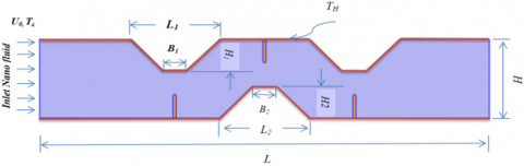
Model description. Figure 1 describes the geometry considered in this study. The problem geometry is a complex two-dimensional channel with a high H and a length of L. The complex channel has a flexible baffle with a thickness of 0.2 mm and a height of 1.5 cm. A flexible baffle is fixed at three locations: the first location is at the lower wall of the channel near the inlet part of the channel, called the case (A); the second location is dangling at the other side of the wall channel towards the midpoint of the bottom wall of the complex channel, called the case (B); and the third location is at the lower wall of the channel near the outlet part of the channel, called the baffle (C). The wall of the complex channel is maintained at a hot temperature (Th). Fluid with uniform velocity (u0) and temperature (Tc) is entering the complex channel filled with Al2O3–water nanofluid. Table 1 offered Properties for Al2O3 nanoparticle and water base fluid The goal of this research is to optimize heat transfer in complex channels with trapezoidal blocks mounted on the walls. This study is applied to different geometric shapes for different ratios L1/H1 (0, 3, and 6), and to unsteady, incompressible, laminar, two-dimensional forced convective flows. The parameter studies were done for the Reynolds number (60 to 160), the Cauchy number of the baffle (1e-4 to 1e-8), and finally the volume fraction of the nanoparticles (0 to 0.04).
Figure 1. Schematic diagram for complex channel with flexible fin
Table 1. Properties for Al2O3, nanoparticle and water base fluid [28]
|
|
ρ (kg/m3) |
Cp (J/kg k) |
k (W/m. k) |
µ)N.s/m2) |
|
Al2O3 |
3880 |
773 |
36 |
- |
|
Pure water |
983.3 |
4179 |
0.595 |
0.000899 |
For the numerical solution of incompressible, unsteady, forced convective flows in the two-dimensional domain, it is the conservation equations of mass, momentum (in the x- and y-directions), and energy for fluid and thermal energy in solid layer which are given, respectively by [30]:
$\nabla \cdot u^*=0$ (1)
$\frac{\partial u^*}{\partial t^*}+\left(u^*-w^*\right) \cdot \nabla u^*=-\frac{1}{\rho_f} \nabla p^*+v_f \nabla^2 u$ (2)
$\frac{\partial T^*}{\partial t^*}+\left(u^*-w^*\right) \cdot \nabla T^*=\alpha_f \nabla^2 T^*$ (3)
$\frac{\partial T^*}{\partial t^*}=\alpha_f \nabla^2 T^*$ (4)
At the interface region between the fluid and the solid, the energy balance can be expressed as:
$\left.K_f \frac{\partial T^*}{\partial n}\right|_f=\left.K_s \frac{\partial T^*}{\partial n}\right|_s$ (5)
where, Ksand Kf, are the thermal conductivities of solid and fluid, respectively, and n is a normal vector.
The elastic wall or fin in the present work with different positions and free displacement fixed with $\frac{\partial d_s^*}{\partial t^*}=0$ at all corner this mean end and starting of piece of elastic line. The condition of the pressure constraint is applied at the exit hole at the right wall, i.e., p*=0.
Dimensional boundary conditions are as follows:
1) The fluid inlet velocity is u*=uin;
2) T*=Th at y=lower and upper wall, 0<x≤L;
3) T*=Tc at x=0, 0<y≤H.
The dimensionless groups appearing in the above equations are defined as follows:
$P_r=\frac{v_f}{\alpha_f}$ is the Prandtl number, $R_e=\frac{u_{i n}(2 w)}{v_f}$ is the Reynolds number, $C_a=\frac{\rho_f u_{i n}^2}{E}$ is the Cauchy number which is defined as the ratio of inertia to elastic forces, $F_{\mathrm{v}}=\frac{C_a H g_y}{\rho_r u_{i n}^2}$ is the dimensionless body force, $\rho_r=\frac{\rho_f}{\rho_s}$ is density ratio, $\alpha_r=\frac{\alpha_s}{\alpha_f}$ is thermal diffusivity ratio.
To obtain the time averaged Nusselt number, the expression above is averaged over a cyclic time period ($\tau$) as follow:
$N u_{a v}=\frac{1}{\tau} \int_0^\tau N u(t)_{a v} d t$ (6)
The physical quantities of interest in this problem are the skin friction coefficient and the Nusselt number, which are defined as [1]:
$C_f=\frac{\tau_w}{\rho U_{i n}^2}$ (7)
where, $\tau$w is the shear stress.
In order to judge the overall performance of the process of heat transfer in the present problem, it is important to calculate a comprehensive criterion. This criterion is a dimensionless term and takes into account the process of the heat transfer and the produced pressure drop through the entire channel. By this criterion, it is possible to inspect the impact of geometrical parameters under different flow conditions [1]:
$T E C=\left(\frac{N u_{a v}}{N u_0}\right)\left(\frac{f}{f_0}\right)^{\frac{1}{3}}$ (8)
where, the subscript "o" stands for the non-baffled channel. The mechanical performance can be evaluated in terms of flow resistance factor (f) as a ratio of wall shear stress to kinetic energy of the flow. The friction factor was estimated from the pressure drop values using the following equation [1]:
$f=\frac{2 \Delta P^* D_h}{\rho u_{i n}^2 L}$ (9)
where, ρ is the fluid density, is the dimensional pressure drop, Dh is the hydraulic diameter (Dh=10H) and L=30 is the length of the channel. The dimensionless pressure drop is obtained from $\Delta P=\frac{\Delta P^*}{\rho U_{i n}^2}, \Delta \mathrm{P}=\mathrm{P}_{\text {out }}-\mathrm{P}_{\text {in }}$ and $\mathrm{f}=\frac{2}{3} \Delta \mathrm{P}$.
The performance evaluation criteria (TEC) were calculated by Eq. (8). Noticeably, TEC>1 means that the heat transfer enhancement is drastically larger than pressure drop.
FSI is used to improve heat transmission. COMSOL 6.0 is used to simulation model. The momentum exchange between the fluid and the deformable baffle was represented using the Navier-Stokes equation. In order to cope with FSI modeling, the arbitrary Lagrangian-Eulerian (ALE) technique based on the finite element method was used to get estimated numerical solutions to the governing Eqns. (1)-(4). These equations were weakly converted and discretized using the Galerkin finite element technique [31, 32]. The movement of the mesh caused by the oscillation of the fin is deemed robust using this technique. The appropriate time step is determined based on the following criteria:
$\Delta t^*=\frac{1}{2} \frac{(\Delta X)^2}{\alpha}$ (10)
where, α the thermal diffusivity of the fluid and Δx is the dimensional distance between nodes in the computational grid,. It is important to remember that the numerical solution's mesh should be taken into consideration while choosing ∆t. Since the present study is dimensionless, relation (10) is modified to be dimensionless as to be:
$\Delta t=\frac{(\Delta t)^* u_{i n}}{H}$ (11)
4.1 Mesh independence, solver and code verification
The current computational domain was given a grid mesh by using a finer grid than was originally intended. In order to halt the calculations, a criteria error of 10-3 has been specified. The relative error formula that is listed below serves as the foundation for the criteria of convergence for the numerical solution:
$\left|\frac{\xi^{m+1}-\xi^m}{\xi^{m+1}}\right| \leq 10^{-6}$ (12)
Any independent variables, where m denotes the number of iterations (velocity, temperature, or pressure). To validate the correctness of the calculated findings, a grid-independent test is now required. Six grid resolutions were used to accomplish this, as shown in Table 2. The average Nusselt number on the heated surface at Ca=1e-4, Re=100, φ=0.02, pr=6.9 was studied during this test. As shown in Figure 2, the grid size of 76662 with 2182 boundary elements was efficient enough to be incorporated in the numerical solution with a percentage error of roughly 0.006. On the other hand, the numerical findings must be confirmed.
Table 2. Grid used in this study
|
Grid |
Domain elements |
Boundary elements |
Time |
Nuav |
Error |
|
G1 |
8729 |
474 |
6 hr+22min |
2.5543 |
- |
|
G2 |
14236 |
590 |
7 hr+11min |
2.8744 |
11.13 |
|
G3 |
29184 |
1152 |
8 hr+25min |
3.0034 |
4.29 |
|
G4 |
70572 |
2170 |
9 hr+34min |
3.1442 |
4.47 |
|
G5 |
76662 |
2182 |
11 hr+43min |
3.1444 |
0.006 |
|
G6 |
121932 |
2214 |
14hr+32min |
3.1445 |
0.003 |
Figure 2. The mesh mode for the present numerical computation
4.2 Validation
Figure 3. The isotherms and streamlines for E=1011, $\tau$=0.5, A=0.1, L=0.25, kr=10, Ra=105
Figure 4. Streamlines and isotherms at n=0.5 and central baffle (X=0.95)
For the confirmation of the program, it is simulated forced convection, unsteady, and incompressible flows at the laminar system for, Prandtl numbers, Pr=0.7, Young's modulus=1011, time=0.5, A=0.1, fin length=0.25, thermal conductivity ratio (fin to fluid)=10, thermal Rayleigh number=105.The isotherm and streamline are compared with the results of Ghalambaz et al. [16], as can be seen in Figure 3. Also present study compared with Yaseen and Ismael [1] for parameters Richardson number=0.01 and Power-law index=0.5 as shown in Figure 4.
This study has been achieved in a force convection laminar regime where Re varies from 60, 100, and 160, different Catchy numbers Ca=10-4, 10-5 and 10-8 and various locations of the deformable baffle with fixed Prandtl number at 6.9 and fixed the length of flexible fin at 1.5cm.
5.1 Steady state time
Unsteady state invested to specify the time where the results get to steady state. For this intent, the behavior of Nusselt number and flexible deformation are invested with dimensionless time as shown in Figures 5 and 6. In this study, time step 0.1 is taken. The choice of time depends on the size of the grid; hence, the time step of 0.1 is most favorable for the previously mentioned grid size. Figure 5 shows that after t=10, the average Nusselt number becomes unaffected by time, and this indicates that the baffle has kept its fixed shape. However, for additional ascertainment, the shape of the baffle with the streamlines has been offered in Figure 6, where the velocity begins to increase with the beginning of the reciprocating movement of the baffle. The acceleration area is formed at the baffle tip, and this is evident at $\tau$=0.1. The acceleration area increases in size with time until it reaches the end of the channel. As for the recirculation area, its formation begins at $\tau$=0.5 and its number and size increase with time. At $\tau$=10, we notice the formation of a recirculation area behind the baffle, in the middle of the channel, and at the end of the channel. The fluid circulates at behind baffle and at the center of channel and also, at the end of the channel. The fresh air is much stronger than the vortices formed behind the baffle, and this causes the baffle to bend forward in the pattern shown in Figure 5. With regard to streamline patterns, there are no considerable differences between times $\tau$=10 and 20, as such, the time at which results are presented in the upcoming sections is $\tau$=10.
Figure 5. Average Nusselt vs. time for Re=160, Ca=1e-4, φ=0.02
Figure 6. Baffle deformation, streamlines for different values of $\tau$ at Re=160, Ca=1e-4, at case (A) near the inlet part
5.2 Heat transfer at various geometry
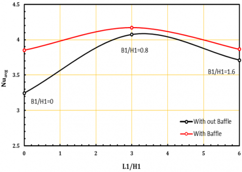
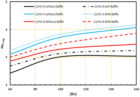
Manufacturing of microelectronic equipment used in various aspects of engineering and biomedical fields has grown rapidly in recent years. It refers to a set of techniques that manage and control the fluid flow and heat dissipation from this equipment. Most of the engineering and biomedical applications involve interaction between the fluid and an elastic structure. Consequently, the manufacturing of such devices requires great attention from the designers. They must take into account some important factors that have a significant impact on the performance of such devices to get accurate and reliable results. For example, fluid flow velocities, pressure, and temperature of the fluid as well as stresses and strains that cause deformations within the elastic structure are important to study carefully. The geometries for a complex channel with different L1/H1 and B1/H1 in case A is investigated. The average Nusselt number investigates three different geometric cases at case (A), the baffle near the channel's inlet. The configurations (L1/H1) are 0, 3, and 6, respectively, with parameters Re=160, Pr=6.9, and φ=0.02. Figures 7 and 8 show the average Nusselt number for three geometries with and without baffles. The result showed the best case with baffle has reached for B1/H1= 0.8 and L1/H1=3 as shown in Figure 7. The improvement with baffle compered without baffle equal 10%. The ratio L1/H1=3 means the increase in the highest intrusion into the channel caused by a trapezoid shape. The interference of the trapezoid in the channel intensifies the mixture of energy behind it. The momentum increases over all trapezoidal and velocity increase. The momentum increases led to increase the mixing and improve the rate of heat transfer. The worst case, reached for B1/H1=0 and L1/H1=0 due to the decrease of the ratio L1/H1, i.e., that mean no intrusion of trapezoidal in flow path but the reciprocating motion of the baffle led to changes marked in the heat transfer. The results showed that an increase Reynolds number leads to an increase in heat transfer as average Nusselt number, as shown in the Figure 8. The best shape of heat transfer is obtained at B1/H1=0.8 and L1/H1=3 at Re=160. Because of the increase in the height of the trapezoid inside the channel, it leads to the interaction of the fresh stream with the hot surfaces, where the boundary layer separates and reconnects, which increases the heat transfer rate by 42% compared to the worst case at B1/H1=0 and L1/H1=0 at Re=60.
Figure 7. Nusselt Number at different geometry at case (A) with Re=160 pr=6.99, φ=0.02, Ca=1e-4
Figure 8. Nusselt Number with Reynolds number at different geometry with Pr=6.9 and φ=0.02, Ca=1e-4
5.3 Effect of Cauchy number
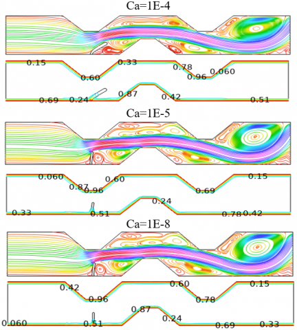
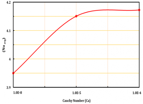
The impact of the Cauchy number on the baffle deformation, isotherms, and streamlines is shown in Figure 9. For Re=160 and the first location of the baffle (the baffle near the inlet part of the channel), the Figure 9 shows the streamline and isotherm side by side for Ca=10-4, 10-5 and 10-8. The baffle vibration affects the area under the baffle. The weak circulation is formed in front of the baffle due to the complex geometry of the channel. The baffle bends forward due to the impact of the fresh flow entering the channel. The weak circulation is broken by the reciprocating motion of the baffle, which easily moves with the flow. At the first case, baffle with Ca=10-4 has a high bending comber with other. The free end of the baffle reaches maximum front deflection, and the eddies have begun to break up. It moves with the flow to the exit of the channel. This improvement can be used to forbid overheating of heat transfer surfaces in systems with a constant rate of heat generation. The isotherms at Ca=10-4 offer a high change in temperature between (0.24 to 0.87) before and behind the baffle, but at Ca=10-5 and Ca=10-8 temperature does not change as shown in Figure 9. The relation between the Cauchy number and the average Nusselt number view at Figure 10. The Nusselt number follows a higher value for Ca=10-4 compared with Ca=10-5 and Ca=1e-8. This is the impact result due to the fluid motion of the baffle fluctuations, where the baffle with Ca=10-4 has a higher elasticity.
Figure 9. Stream line and isotherm at the baffle A (near the inlet part) at Re=160, Ca=1e-4, φ=0.02
Figure 10. The relation between Cauchy Number and Average Nusselt Number at the case A (near the inlet part) at Re=160, φ=0.02
5.4 Impact of the baffle location
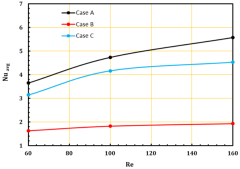
In this section, the effect of the location of the baffle is analyzed at Ca=10-4, Re=160, φ=0.02 and Pr=6.9. The Figure 11 offers a streamline of velocity at three locations: case A (the baffle near the inlet flow of the channel), case B (the baffle at the center of the channel), and case C (the baffle near the outlet of the channel). The figure offers the range of velocities between (2.79e-6) is the recirculation area, and (5.94), which is the acceleration area, as shown in Figure 11. In case A, the flow enters the channel directly and moves intensively along the channel, with a range of velocities nearly between zero at the wall of the channel due to surface friction and two at the center of the channel. The velocity begins to gradually increase until it reaches its maximum of 5.94 after trapezoidal first penetration in the flow due to the reciprocating motion of the baffle and continues to the end of the channel compared with cases B and C. At the front of the baffle, the recirculation area is formed due to the complex channel shape, and the velocity after the baffle is less than before the baffle, so the fresh flow entering the channel pushes the baffle forward. Another extended recirculation area is formed at the center and others at the exit part of the channel due to the corners of the trapezoid, which lead to the fluid eddies. In case B, the baffle is located at the center of the channel. This brings the space of the channel to be narrow. Consequently, due to the reciprocating motion of the baffle, the long, extended recirculation area breaks into small vortices that are easy to transport with the flow. Also, a vortex with two eyes is formed at the exit part of the channel near the angles of trapezoidal but missing at the front of the channel. In case C, where the baffle is located close to the outlet of the channel, the baffle breaks the vortices into small parts and also forms a small recirculation area at the corner of the trapezoidal at the center of the channel and a vortex with two eyes at the exit channel. The relationship between the Nusselt number and the Reynolds number in all cases (A, B, and C) is shown in Figure 12. It shows that the first location (case A) records the high Nusselt number at Re=160, the improvement is 52% compare with low Nusselt number at (case B) at Re=60 due to bring out the fresh fluid towards the outlet of channel by the baffle that means the fresh fluid entering pushes the baffle forward. The reciprocating movement of the baffle breaks the vortices that formed due to the trapezoidal shape to the small eddies that are easy to transport with the flow.
Figure 11. Streamline at cases (A,B,C) for Re=160, Pr=6.9, φ=0.02, Ca=1e-4
5.5 The effect of heat transfer for a hot wall
The Nusselt number is studied to obtain the best heat transfer performance. The Nusselt number is determined along the hot wall to measure the quality of thermal performance by convection. The Figure 13 displays Nusselt along the wall of the general channel. There is a slight change in the Nusselt number near the entrance to the channel S=0-6, where the rate of heat transfer is weakly. At the baffle A region between S=6-12, a gradual rise in Nusselt number is observed until it reaches to value 18 at the free part of the baffle due to the heat transfer in this part. The fluid structure interaction can work well to drain the fin to get a very flexible fin that contributes to the heat transfer process. After the tip region, the Nusselt begins to decrease gradually until it reaches value 6 It indicates that the cold heavy liquid is formed at vortices, which leads to the rotation of the liquid and the denser liquid is pushed to the bottom. Between S=12 and 18, the Nusselt-Number number little high. At this part the channel is narrowed due to the complex shape of the channel. The baffle B in this part does not contribute to improve the heat transfer rate because it does not take the comfortable shape in the process of fluid structure interaction. Between S=20 and 24, the Nusselt number again rises to 16 at the last part of the channel due to the location of baffle D fluid structure interaction. At the end of the channel (after baffle D) the Nusselt number has dropped to value 6.
Figure 12. The relation between average Nusselt number (Nuavg) and Reynolds Number (Re) at Ca=1e-4, Pr=6.9
Figure 13. Local Nusselt number along the hot wall at three cases with Re=160, Pr=6.9, φ=0.02
5.6 Impact of the pressure drop
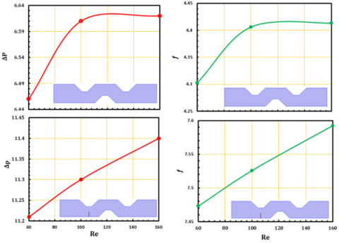
It is not only possible to study the Nusselt number to get the best performance, the pressure drop and friction factor must also be studied because they require high pumping power. Average Nusselt number with Reynolds number at L1/H1=3, Ca=1e-4 with Pr=6.9 and φ=0.02 is investigated as shown in Figure 14. Generally, the Nussult number increases with the Reynolds number due to increase velocity and mixing. The results registered a high value of Nusslet number with baffle at Re=160 comparison without baffle reached to 52%. Also, the pressure drop increases with Reynolds number due to an increase in the fraction factor, as shown in Figure 15. The friction factor is also significant to be studied in the characterization of pumping power. This means that, although the pressure drop increases due to the higher Reynolds number, this generates strong eddy currents and therefore a higher friction factor. The results show out, dass the pressure drop and friction factor in case (A) L1/H1=3 with baffle at Re=160 reach to 11.4 and 7.59 respectively due to the generation of strong vortices with high Reynolds number but low pressure drop and friction factor without baffle at Re=60.
Figure 14. Average Nusselt number with Reynolds number at case A (baffle near the inlet part) at Ca=1e-4, Pr=6.9 and φ=0.02
Figure 15. The relation of pressure drop and friction factor with Reynolds number at Ca=1e-4, Pr=6.9 and φ=0.02
5.7 Effect of working fluid
Previously obtained results showed that the best heat transfer performance is in case A when the baffle is near the inlet portion of the channel at Re=160 and Ca=1E-4. Hence, the Nusselt number with nanoparticles of Al2O3 concentration (0-0.02-0.04) was achieved in Figure 16. Where the figure shows that the larger size of the nanoparticles increases of Nusselt number due to the increase in the surface area of heat transfer.
Figure 16. Average Nusselt number with nanoparticle concentration at Ca=1e-4, Pr=6.9 and φ=0.02
5.8 Thermal performance
To obtain the best performance must not be based only on the Nusselt number, the pressure drop and friction factor must be studied because they require high pumping power. Thermal enhancement criterion (TEC) mentioned in equation (8) achieve this issue. Figure 17 describe that the best thermal enhancement criterion (TEC) can be achieved at case A when the baffle is located near the inlet part of complex channel. This mean that the increment of the average Nusselt number beat the losses that result from the pressure drop along the channel. The high thermal enhancement criterion (TEC) is recorded 1.8 at case A for Re=160 and lowest value 0.6 at Case B for Re=60.
Figure 17. Variations of thermal-hydraulic performance criterion with baffles location and Reynolds numbers at Ca=1e-4, φ=0.02
In this paper, a numerical study of fluid-structure interaction in a complex channel with a trapezoidal shape is investigated. The degrees of freedom (L1/H1 and B1/H1) for Reynolds numbers 160 were investigated. The deformable baffle is used to direct flow over a hot source. For all cases, it was considered a Prandtl number (Pr=6.99). Different locations of the baffle with the Reynolds number have led to results with the following conclusions:
1) The elastic (deformable) baffle contributes to an increase in the average Nusselt number. The Nusslet number reached a high value with baffle at a Re=160 comparison; without baffle, it reached 52%. Also, the pressure drop increases with Reynolds number due to the increased fraction factor.
2) In Case A, where the deformable baffle is closer to the start of the channel, the maximum Nusselt number is reached.
3) The best thermal performance of corrugated channels at B1/H1=0.8 and L1/H1=3, which improved the heat exchanger under the present thermal conditions.
4) The average Nusselt number follows a higher value for Ca=1e-4 compared with Ca=1e-5 and Ca=1e-8.
5) The larger size of the nanoparticles increases, Nusselt number.
|
u0 |
Uniform velocity m2 |
|
T |
Temperature K |
|
K |
Thermal conductivity W/m.k |
|
h |
Convection heat transfer W/m2.k |
|
u, v |
x-y velocity components m/s |
|
Ca |
Cachy number |
|
cp |
Specific heat J/kg.k |
|
P |
Pressure Pa |
|
F |
Force N |
|
n |
normal vector |
|
Greek symbols |
|
|
µ |
Dynamic viscosity (Pa.s) |
|
φ |
Nanoparticles volume concentration (%) |
|
θ |
Non-dimensional temperature |
|
ρ |
Density (kg/m3) |
|
ν |
Kinematic viscosity of the fluid m2/s |
|
α |
Thermal diffusivity m2/s |
|
σ |
Stress tensor N/m2 |
|
$\nabla $ |
Cartesian coordinate vector M |
|
$\tau$ |
Time period S |
|
Subscripts |
|
|
FSI |
Fluid-structure interactions |
|
CFD |
Computation Fluid Dynamic |
|
ALE |
Arbitrary Lagrangian Eulerian |
|
FEM |
Finite Element Method |
[1] Yaseen, D.T., Ismael, M.A. (2020). Effect of deformable baffle on the mixed convection of non-newtonian fluids in a channel-cavity. Basrah Journal for Engineering Sciences, 20(2): 18-26.
[2] Xu, H., Liao, S.J. (2009). Laminar flow and heat transfer in the boundary-layer of non-Newtonian fluids over a stretching flat sheet. Computers & Mathematics with Applications, 57(9): 1425-1431. https://doi.org/10.1016/j.camwa.2009.01.029
[3] Hessenthaler, A., Gaddum, N.R., Holub, O., Sinkus, R., Röhrle, O., Nordsletten, D. (2017). Experiment for validation of fluid‐structure interaction models and algorithms. International Journal for Numerical Methods in Biomedical Engineering, 33(9): e2848. https://doi.org/10.1002/cnm.2848
[4] Jamesahar, E., Ghalambaz, M., Chamkha, A.J. (2016). Fluid–solid interaction in natural convection heat transfer in a square cavity with a perfectly thermal-conductive flexible diagonal partition. International Journal of Heat and Mass Transfer, 100: 303-319. https://doi.org/10.1016/j.ijheatmasstransfer.2016.04.046
[5] Al-Amiri, A., Khanafer, K. (2011). Fluid–structure interaction analysis of mixed convection heat transfer in a lid-driven cavity with a flexible bottom wall. International Journal of Heat and Mass Transfer, 54(17-18): 3826-3836. https://doi.org/10.1016/j.ijheatmasstransfer.2011.04.047
[6] Mehryan, S.A.M., Ghalambaz, M., Ismael, M.A., Chamkha, A.J. (2017). Analysis of fluid-solid interaction in MHD natural convection in a square cavity equally partitioned by a vertical flexible membrane. Journal of Magnetism and Magnetic Materials, 424: 161-173. https://doi.org/10.1016/j.jmmm.2016.09.123
[7] Sabbar, W.A., Ismael, M.A., Almudhaffar, M. (2018). Fluid-structure interaction of mixed convection in a cavity-channel assembly of flexible wall. International Journal of Mechanical Sciences, 149: 73-83. https://doi.org/10.1016/j.ijmecsci.2018.09.041
[8] Selimefendigil, F., Öztop, H.F. (2018). Laminar convective nanofluid flow over a backward-facing step with an elastic bottom wall. Journal of Thermal Science and Engineering Applications, 10(4).
[9] Selimefendigil, F., Öztop, H.F. (2019). Fluid-solid interaction of elastic-step type corrugation effects on the mixed convection of nanofluid in a vented cavity with magnetic field. International Journal of Mechanical Sciences, 152: 185-197.
[10] Ismael, M.A. (2019). Forced convection in partially compliant channel with two alternated baffles. International Journal of Heat and Mass Transfer, 142: 118455. https://doi.org/10.1016/j.ijheatmasstransfer.2019.118455
[11] Alsabery, A.I., Saleh, H., Ghalambaz, M., Chamkha, A.J., Hashim, I. (2019). Fluid-structure interaction analysis of transient convection heat transfer in a cavity containing inner solid cylinder and flexible right wall. International Journal of Numerical Methods for Heat & Fluid Flow, 29(10): 3756-3780. https://doi.org/10.1108/HFF-10-2018-0593
[12] Ghalambaz, M., Mehryan, S.A.M., Ismael, M.A., Chamkha, A., Wen, D. (2019). Fluid–structure interaction of free convection in a square cavity divided by a flexible membrane and subjected to sinusoidal temperature heating. International Journal of Numerical Methods for Heat & Fluid Flow, 30(6): 2883-2911. https://doi.org/10.1108/HFF-12-2018-0826
[13] Al-Amir, Q.R., Hamzah, H.K., Abdulkadhim, A., Ahmed, S.Y., Ali, F.H., Abed, A.M., Abed, I.M. (2022). Numerical study of fluid structure interaction of four flexible fins inside nanofliud-filled square enclosure containing hot circular cylinder. Journal of Thermal Analysis and Calorimetry, 1-19. https://doi.org/10.1007/s10973-022-11535-w
[14] Tsay, Y.L., Cheng, J.C., Chang, T.S. (2003). Enhancement of heat transfer from surface-mounted block heat sourcesin a duct with baffles. Numerical Heat Transfer: Part A: Applications, 43(8): 827-841. https://doi.org/10.1080/713838151
[15] Sharma, A.K., Mahapatra, P.S., Manna, N.K., Ghosh, K. (2015). Mixed convection in a baffled grooved channel. Sadhana, 40: 835-849. https://doi.org/10.1007/s12046-014-0328-4
[16] Ghalambaz, M., Jamesahar, E., Ismael, M.A., Chamkha, A.J. (2017). Fluid-structure interaction study of natural convection heat transfer over a flexible oscillating fin in a square cavity. International Journal of Thermal Sciences, 111: 256-273. https://doi.org/10.1016/j.ijthermalsci.2016.09.001
[17] Alsabery, A.I., Sheremet, M.A., Ghalambaz, M., Chamkha, A.J., Hashim, I. (2018). Fluid-structure interaction in natural convection heat transfer in an oblique cavity with a flexible oscillating fin and partial heating. Applied Thermal Engineering, 145: 80-97. https://doi.org/10.1016/j.applthermaleng.2018.09.039
[18] Ismael, M.A., Jasim, H.F. (2018). Role of the fluid-structure interaction in mixed convection in a vented cavity. International Journal of Mechanical Sciences, 135: 190-202. https://doi.org/10.1016/j.ijmecsci.2017.11.001
[19] Abdi, R., Rezazadeh, N., Abdi, M. (2019). Investigation of passive oscillations of flexible splitter plates attached to a circular cylinder. Journal of Fluids and Structures, 84: 302-317. https://doi.org/10.1016/j.jfluidstructs.2018.11.001
[20] Sun, X., Ye, Z., Li, J., Wen, K., Tian, H. (2019). Forced convection heat transfer from a circular cylinder with a flexible fin. International Journal of Heat and Mass Transfer, 128: 319-334. https://doi.org/10.1016/j.ijheatmasstransfer.2018.08.123
[21] Selimefendigil, F., Oztop, H.F., Chamkha, A.J. (2019). MHD mixed convection in a nanofluid filled vertical lid-driven cavity having a flexible fin attached to its upper wall. Journal of Thermal Analysis and Calorimetry, 135: 325-340. https://doi.org/10.1007/s10973-018-7036-y
[22] Saleh, H., Hashim, I., Jamesahar, E., Ghalambaz, M. (2020). Effects of flexible fin on natural convection in enclosure partially-filled with porous medium☆. Alexandria Engineering Journal, 59(5): 3515-3529. https://doi.org/10.1016/j.aej.2020.05.034
[23] Jamesahar, E., Sabour, M., Shahabadi, M., Mehryan, S. A.M., Ghalambaz, M. (2020). Mixed convection heat transfer by nanofluids in a cavity with two oscillating flexible fins: A fluid–structure interaction approach. Applied Mathematical Modelling, 82: 72-90. https://doi.org/10.1016/j.apm.2019.12.018
[24] Hamzah, H.K., Al-Amir, Q.R.A., Abdulkadhim, A., Ahmed, S.Y., Ali, F.H., Abed, A.M., Abed, I.M. (2022). In a vented square enclosure, the effect of a flexible baffle attached to a solid cylinder on mixed convection. Arabian Journal for Science and Engineering, 47(12): 15489-15504. https://doi.org/10.1007/s13369-022-06595-x
[25] Naphon, P. (2008). Effect of corrugated plates in an in-phase arrangement on the heat transfer and flow developments. International Journal of Heat and Mass Transfer, 51(15-16): 3963-3971. https://doi.org/10.1016/j.ijheatmasstransfer.2007.11.050
[26] Sakr, M. (2015). Convective heat transfer and pressure drop in V-corrugated channel with different phase shifts. Heat and Mass Transfer, 51(1): 129-141. https://doi.org/10.1007/s00231-014-1390-5
[27] Ajeel, R.K., Salim, W.I., Hasnan, K. (2018). Thermal and hydraulic characteristics of turbulent nanofluids flow in trapezoidal-corrugated channel: Symmetry and zigzag shaped. Case Studies in Thermal Engineering, 12: 620-635. https://doi.org/10.1016/j.csite.2018.08.002
[28] Salami, M., Khoshvaght-Aliabadi, M., Feizabadi, A. (2019). Investigation of corrugated channel performance with different wave shapes: Nanofluid as working media. Journal of Thermal Analysis and Calorimetry, 138: 3159-3174. https://doi.org/10.1007/s10973-019-08361-y
[29] Al-Zurfi, N., Alhusseny, A., Nasser, A. (2020). Effect of rotation on forced convection in wavy wall channels. International Journal of Heat and Mass Transfer, 149: 119177. https://doi.org/10.1016/j.ijheatmasstransfer.2019.119177
[30] Donea, J., Huerta, A. (2003). Finite Element Methods for Flow Problems. John Wiley & Sons.
[31] Bejan, A. (2013). Convection Heat Transfer. John wiley & sons.
[32] Donea, J., Giuliani, S., Halleux, J.P. (1982). An arbitrary Lagrangian-Eulerian finite element method for transient dynamic fluid-structure interactions. Computer Methods in Applied Mechanics and Engineering, 33(1-3): 689-723. https://doi.org/10.1016/0045-7825(82)90128-1