Mohammad Saraireh![]()
© 2023 IIETA. This article is published by IIETA and is licensed under the CC BY 4.0 license (http://creativecommons.org/licenses/by/4.0/).
OPEN ACCESS
In electric vehicles (EVs), maintaining the battery, motor, electric control, and crew cabin at the right temperature for maximum performance is the major goal of thermal management. The integrated thermal management system, which is viewed from the viewpoint of the vehicle system, coordinates and regulates the vehicle's capacity to disperse heat. Electricity is used by the EVs' air-conditioning systems to create a comfortable environment within the passenger space. However, if the motor drive gets too hot, its effectiveness will decline. A viable battery thermal management approach is needed to control the battery temperature within an optimum range and decrease temperature inconsistency in the battery module since temperature has a significant impact on the cycle life and capacity of the power battery in electric vehicle. This study provides a comparative review by discussing the fundamentals of heat transport and thermal management systems. Describe the heat generation model of each subsystem's thermal management and introduce its thermal management approach, concentrating on the research status and operation control of the integrated thermal management system. After compiling the flaws of the preceding studies, further research options were recommended. In the near future, it will be crucial to conduct extensive research into accurate heat generation models, develop a small-footprint integrated thermal management system, and enhance integrated thermal management system operation control.
heat transfer, thermal management, battery optimization, electrochemical
The two biggest issues the world is currently confronting are the escalating energy crisis and environmental degradation [1]. Electric cars are superior to conventional cars, including better performance [2], lower pollutant emissions [3], and the ability to effectively address the energy crisis and environmental issues. Electric car development is accelerating in all nations. The performance of the battery is significantly influenced by temperature [4, 5]. When charging and discharging batteries, high temperatures can lead to battery degradation, breakdown, or even explosion [6, 7]. It is challenging to use the waste heat of an internal combustion engine for heating in the winter while an electric car has to be cooled in the summer since the compressor is powered by the motor [8]. The air conditioning system of electric vehicles uses the most energy of all the auxiliary systems [9], which has a significant impact on the vehicle's mileage [10]. Additionally, the motor drive system's lifespan and efficiency would drastically decrease at high temperatures [11]. Therefore, creating an effective thermal management system to maintain a proper temperature range for the battery, passenger area, and motor drive system is a vital step to further the development of electric cars.
With the development of 3D chip stacking technology, the integration of electronic devices continues to increase at a rate of 40% to 50% per year. In electronic devices, a considerable part of the power loss is converted into heat. For example, in the 1980s, the heat flux density of integrated circuits was about 10 W/cm2. it increased to 20~30 W/cm2 in the 1990s, and it was close to 100 W/cm2 in 2008, and the current chip-level heat flux density has exceeded 1 kW/cm2, and the heat flux density of local hot spots can even reach 30 kW/cm2 [12-14]. In order to ensure that a large amount of heat generated by heat-generating electronic components can be dissipated in a timely and effective manner, thermal management has become an important aspect to be considered in the assembly of microelectronic product systems.
The automotive thermal management system starts from the system integration and overall perspective, and designs the relationship between the heat and the engine and the overall body, using advanced materials, electronic and intelligent means to control and optimize the heat transfer and distribution [15-17]. The automotive thermal management system includes engine cooling system, heating ventilation and air conditioning (HVAC) system and engine exhaust heat recovery system, etc. The quality of its working performance directly affects the overall performance of the automotive power system. The thermal management materials involved in the automotive thermal management system are more extensive, including thermoelectric materials for vehicle exhaust heat recovery and seat temperature regulation [18], phase change materials for vehicle preheating and battery management (PCM) [19] and nanofluids for high thermal conductivity cooling liquids [20], etc.
For advanced battery systems (lithium batteries, fuel cells, nickel-metal hydride batteries, etc.), the thermal management system needs to effectively dissipate heat when the battery temperature is high, and preheat when the temperature is low to increase the battery temperature and ensure that the battery temperature is low. At the same time, it is necessary to reduce the temperature difference in the battery pack to keep the battery pack in good consistency [21-23]. The advanced battery thermal management system needs to be based on the influence of temperature on the charge-discharge performance curve of the battery, combined with the electrochemical characteristics and heat generation mechanism of the battery, and based on the optimal charge-discharge temperature range of the specific battery, through reasonable design, to solve the problem of the battery's temperature over-temperature. To improve the overall performance of the battery, the battery performance is degraded or even failed due to working under high or low conditions. In pure electric vehicles, hybrid electric vehicles and other power systems that use power batteries as the power source, battery thermal management is of great significance, not only related to the overall operating efficiency of the car, but also related to the safety performance of the car itself. Traditionally, the thermal management system of the battery pack is mainly based on liquid cooling or air cooling, but the recent application of phase change materials in the thermal management of the battery pack makes the thermal management begin to develop in the direction of solid cooling [24].
Thermal Interface Material (TIM) plays a key role in the thermal management of electronic components and is an important research branch in this discipline [25]. When microelectronic materials or devices are bonded to each other, the actual contact area is only 10% of the macroscopic contact area, while the rest are air-filled gaps. The thermal conductivity of air is lower than 0.03 W/(m·K) [26], which is a poor conductor of heat, which reduces the system scattering efficiency. Filling these gaps with thermal interface materials with high thermal conductivity and ductility to create gapless contacts between the microelectronic device and the heat sink can dramatically reduce contact thermal resistance.
High thermal conductivity, which lowers the thermal resistance of the thermal interface material itself, and high flexibility, which ensures that the thermal interface material can be used to its fullest under conditions of low installation pressure, are two qualities that the ideal thermal interface material should possess. Insulation, ease of installation and detachment, wide range of applications (both may be used for), and modest contact thermal resistance between the thermal interface material and the contact surface are the other four. Both minor and large holes should be filled [27].
As the requirements for safe heat dissipation in microelectronics are getting higher and higher, thermal interface materials are also constantly developing. Thermal grease is the earliest widely used thermal interface material and has achieved good results. However, due to its difficulties in operation and use and easy failure after long-term use [28], it has gradually given way to other new thermal interface materials. Polymer-based thermal interface materials composited with inorganic nanomaterials is an important development direction [29].
Inorganic nanofillers are widely used in the mechanical reinforcement of polymer materials, the improvement of electrical conductivity, and the improvement of thermal conductivity. As a thermal interface material, high thermal conductivity is required. The thermal conductivity of common polymer materials and rubber materials is relatively low. Inorganic fillers such as alumina [30], aluminum nitride [31], silicon carbide [32], boron nitride [33] and carbon nanotubes [34] can effectively improve the thermal conductivity of polymer materials, but have the existing problems are: the addition of inorganic fillers will make the polymer material brittle and hard, and the processability and flexibility will decrease, which just makes the advantage of the polymer as a highly processable material lost.
The performance, life and safety of lithium batteries are very sensitive to temperature [35-37], and they will suffer severe capacity fading [38] below zero degrees Celsius, and thermal runaway caused by waste heat accumulation may lead to fire or even explosion [39, 40]. An efficient battery thermal management system (BTMS) must be used to maintain the proper temperature range of the battery and improve its operating efficiency and life cycle [41-43]. The medium substances of the pure electric vehicle battery thermal management system are generally divided into air [44], liquid [45, 46], phase change material [47], heat pipe [48] and the combination of the above four media. Some scholars have proposed that the integrated thermal management (ITM) system generally combines the air conditioning system and BTMS, and even involves the recovery of waste heat from the motor, which reduces the components of the system to a certain extent. Compared with the positive temperature coefficient heater, the ITM system proposed by [49, 50] can reduce the operating cost per 100 kilometers by 20.83%. Reference [51] proposed an ITM system that recovers waste heat from motors and controllers. On the basis of saving operating costs, the payback period is 4.57 to 6.77 years. However, most of the current research on ITM propose systems that only connect another evaporation branch in parallel with the evaporation branch. The composition of the ITM system proposed in references [50-56] is generally as follows: when cooling, the battery heat exchanger is used in parallel with the heat exchanger inside the air conditioning system. When heating, the motor heat exchanger is used in parallel with the outside heat exchanger of the air conditioning system, that is, the system adopts the parallel mode. Reference [57] pointed out that the evaporation temperature of the battery heat exchanger is relatively high during refrigeration, it is placed in front of the heat exchanger in the cabin, that is, the system adopts a series mode. It is believed that this can not only improve the temperature fluctuation in the cabin, but also better ensure the temperature drop characteristics of the battery, but not for the heat pump mode. It is worth mentioning that the ITM system combined with vapor injection (V-I) and waste heat utilization [58]. Compared with the V-I system, it has increased by 13.57% and 7.88% respectively.
The two or three subsystems that make up the integrated thermal management system for electric automobiles are the thermal management of the battery, the thermal management of the passenger compartment, and the thermal management of the motor drive system. Each thermal management subsystem's performance has an impact on the others, and these relationships are intricately coupled. More study findings in the fields of battery thermal management, passenger compartment thermal management, and motor drive system thermal management have recently been made.
In order to effectively evaluate the performance of various methods, the following contributions are outlined:
·This paper begins by outlining the primary aspects in heat transfer and thermal management system.
·Describe the heat production model of each subsystem’s thermal management and introduce its thermal management strategy, focusing on the analysis of the integrated thermal management system's research status and its operation control.
·The challenges that need to be overcome in the integrated thermal management system study for electric cars are then summarized, along with suggestions for the future.
The remaining of the paper is organized as follows. In Section 2, the heat production model is described in terms of mathematical and graphical illustrations. In Section 3, the thermal management methods were discussed. In Section 4, the Integrated operation system is discussed. In Section 5, the performance evaluation is performed while Section 6 concludes the paper.
To effectively address the issue of heat generation and transfer inside the vehicle is the function of the thermal system. Calculating the cooling and heating demand for the entire vehicle helps choose the best air conditioning system. As a result, the accurate formulation of the heat generation model of each subsystem is the design optimization of the combined thermal management system.
2.1 Battery heat generation model
The three classifications that the battery heat generating model may be placed under are the electrochemical-thermal linked model, the electrical-thermal connected model, and the thermal abuse model. In this paper, the electrical-thermal coupled model and the electrochemical-thermal coupled model are principally introduced under realistic operating conditions. The battery's heat generation and heat dissipation processes are unstable, per the energy conservation equation, since their internal heat source fluctuates over time [59]:
$\rho c \frac{\partial T}{\partial \tau}=\nabla \cdot(\lambda \nabla T)+\dot{q}$ (1)
In the formula, ρ is the density of the battery cell, kg.m-3; c is the specific heat capacity of the battery unit, J·(kg·K)-1; λ is the thermal conductivity of the battery cell, W·(m·K)-1; T is the temperature of the battery unit in K; τ is time in s; $\dot{q}$ is the heat production rate of the battery cell, W.m-3. It can be seen from Eq. (1) that the heat transfer problem of the battery temperature field distribution can be solved by solving the differential equation of thermal conductivity of the battery, so the calculation of the heat production rate of the battery is one of the keys to solve the thermal problem. The Bernardi heat production rate model is now the most often used approach for determining the battery heat generation rate [60]:
$\dot{q}=\frac{I}{V_b}\left(U_{0^{-}} U\right)-\frac{I}{V_b}\left(T \frac{d U_0}{d T}\right)$ (2)
In the formula, I is the current in A; Vb is the battery volume, m3; U0 is the open circuit voltage in V; U is the working voltage in V.
The electrochemical-thermal coupling model is based on the heat production of electrochemical reaction, and the law of energy conservation is used to study the thermal characteristics inside the battery, and then guide the microscopic design of the internal parameters of the battery cell. The primary methods used to study the thermal properties of batteries in recent years include enlarging the model [61] and improving the procedures for producing and transferring heat [62, 63]. He et al. [64] proposed an electrochemical modeling of the thermal coupling (Figure 1) is used to study the heat distribution and temperature field prediction of the internal layered structure of the battery.
Figure 1. Illustration of electro-chemical and thermal coupling structure
The macro-design of the battery size, electrode size, electrode distribution, and battery pack cooling system is often guided by the electric-thermal coupled model, which simulates the temperature distribution by computing the current distribution inside the battery. Lyu et al. [65] established a three-dimensional electric-thermal coupled model of LiFePO4 battery based on the Bernardi heat production rate model. The mathematical control equations are:
$\rho_p C_p \frac{\partial T}{\partial \tau}=k_{p x} \frac{\partial^2 T}{\partial x^2}+k_{p y} \frac{\partial^2 T}{\partial y^2}+k_{p z} \frac{\partial^2 T}{\partial z^2}+\dot{q}_p-\dot{q}_{f p}$ (3)
$\rho_n C_n \frac{\partial T}{\partial \tau}=k_{n x} \frac{\partial^2 T}{\partial x^2}+k_{n y} \frac{\partial^2 T}{\partial y^2}+k_{n z} \frac{\partial^2 T}{\partial z^2}+\dot{q}_n-\dot{q}_{fn}$ (4)
$\rho_r C_r \frac{\partial T}{\partial \tau}=k_{r x} \frac{\partial^2 T}{\partial x^2}+k_{r y} \frac{\partial^2 T}{\partial y^2}+k_{r z} \frac{\partial^2 T}{\partial z^2}+\dot{q}_r-\dot{q}_{f r}$ (5)
$\dot{q}_p=J_p\left(U_{0^{-}} U-T \frac{d U_0}{d T}\right)+I_p^2 R_{p p}$ (6)
$\dot{q}_n=J_n\left(U_0-U-T \frac{d U_0}{d T}\right)+I_n^2 R_{p n}$ (7)
$\dot{q}_r=0$ (8)
$J_p=\sigma_{c p} \cdot \Delta \emptyset_p$ (9)
$J_n=\sigma_{c n} \cdot \Delta \emptyset_n$ (10)
$\Delta \emptyset_p=\frac{I_{t p}}{\sigma_{c p} h_p S_p}$ (11)
$\Delta \varnothing_n=\frac{I_{t n}}{\sigma_{c n} h_n S_n}=0$ (12)
In the formula, ρp, ρn, ρr are the densities of the positive electrode current collector, the negative electrode current collector and the battery plate, respectively in kg.m−3; Cp, Cn, Cr are the specific heat capacity of the current collector of the positive electrode sheet, the current collector of the negative electrode sheet and the battery plate in J·(kg·K)−1; kpx, kpy, kpz are the thermal conductivity along the x, y and z directions in the positive electrode sheet in W·(m·K)−1; knx, kny, knz are the thermal conductivity along the x, y, and z directions in the negative electrode sheet in W·(m·K)−1; krx, kry, krz are the thermal conductivity along the x, y and z directions in the battery plate in W·(m·K)−1; $\dot{q}_p$, $\dot{q}_n$, $\dot{q}_r$ are the heat production rates of the positive electrode current collector, the negative electrode current collector and the battery plate in W.m−3; $\dot{q}_{f p}$, $\dot{q}_{f n}$, $\dot{q}_{f r}$ are the heat dissipation rates of the positive electrode current collector, the negative electrode current collector and the battery plate in W.m−3; Jp, Jn are the current density in the positive and negative sheets in A.m−3; Ip, In are the currents flowing through the positive and negative current collectors, respectively in A; Rpp, Rpn are the equivalent polarization internal resistances of the positive and negative current collectors, respectively, Ω; σcp, σcn are the conductivity of the positive and negative plates in S.m−1; $\Delta \emptyset_p$, $\Delta \emptyset_n$ are the potential difference between the positive and negative electrodes in V; Itp, Itn are the currents flowing through the positive and negative plates in A; hp, hn are the thicknesses of the positive and negative plates in m; Sp, Sn are the area of the positive and negative plates in the xy plane in m2. The heat generation and heat dissipation characteristics of the battery under natural cooling and forced air convection heat transfer cooling were studied by the model simulation, and the position of the air outlet was optimized based on the simulation results [66].
2.2 Air Conditioning cooling and heating load
The determination of the heating and cooling load of electric vehicles is based on the calculation method of building cooling and heating load, considering the car as a “moving building” and the passenger cabin as a “moving room”. The calculation methods of cooling and heating load of automobile air conditioners can be divided into three types: steady-state heat transfer method, quasi-steady-state heat transfer method and non-steady-state heat transfer method [67]. Considering that there are many factors affecting the cooling and heating load of the vehicle, including meteorological parameters, body structure and materials, vehicle speed, the number of occupants, the calorific value of electrical appliances in the passenger compartment and the calorific value of the battery pack [67]. At present, the calculation of the heating and cooling load of electric vehicles usually adopts the steady-state heat transfer method, and the influence of the changes of different parameters on the cooling and heating load of the whole vehicle is studied in real time through the simulation software. Miri et al. [68] used one-dimensional simulation software to explore the biggest factor affecting the heat load of the vehicle in summer according to Eq. (13). The results showed that the lower the absorption ratio and transmittance of the front window glass, the greater the installation inclination, and the higher the front window glass. The incoming heat load is smaller.
$Q_E=Q_e+Q_b+Q_a+Q_p+Q_g+Q_{b a}$ (13)
In the formula, QE, Qe, Qb, Qa, Qp, Qg, and Qba are the total heat load of the passenger compartment, respectively, the heat load introduced into the passenger compartment through the body envelope, the heat load introduced into the passenger compartment through the window, and the inside of the vehicle. The heat dissipated by the driver and passengers, the heat load of the fresh air, the heat load of the electrical appliances in the passenger compartment and the heat load of the battery pack into the passenger compartment, all in W.
2.3 Motor heat generation model
In the process of converting electrical energy into mechanical energy, the motor will generate energy loss, which mainly includes iron core loss, winding loss and mechanical loss.
At present, the Bertotti discrete iron loss model [69] is commonly used to calculate the iron core loss of the motor, and its expression is as follows:
$P_{F e}=k_h f B^\alpha+k_e f^2 B^2+k_\alpha f^{1.5} B^{1.5}$ (14)
In the formula, the three terms on the right side of the equal sign are hysteresis loss, eddy current loss and additional loss respectively, f is the frequency of the alternating magnetic field in Hz; B is the magnitude of the fundamental magnetic flux density in Wb.m−2; kh, ke and kα are loss coefficients.
The winding loss is mainly the basic copper loss, which can be obtained according to the Joule-Lenz law:
$P_{c u i}=\sum I_i^2 R_i$ (15)
In the formula, Pcui is the copper loss value of the winding in W; Ii is the current in the winding in A; Ri is the resistance of the winding during operation in Ω.
The mechanical losses can usually be calculated from empirical formulas.
The above heat production model can basically satisfy the calculation of heat production by different heat sources in the integrated thermal management system, but it needs to be further improved for the description of the complex heat production process.
Electric vehicle batteries, passenger compartments and motor drive systems have all developed corresponding thermal management methods for their respective thermal management needs. The system effect, dynamic response characteristics and economy have all put forward more stringent requirements, and existing researches focus on coupling different thermal management subsystems on the basis of optimizing the performance of a thermal management system.
3.1 Battery thermal management
The thermal management of batteries comprises heating the batteries at low temperatures and cooling them at high temperatures. The thermal management of batteries may be split into air, liquid, phase change material, and heat pipe systems depending on the medium. Due to its benefits of a straightforward form, cheap cost, and simple maintenance, the air thermal management system was initially used to the battery thermal management system [70]. However, with the increase of the energy density of the battery pack and the development of fast charging technology, the battery pack will generate a lot of heat in a short time. The research results show that it is difficult to control the temperature and temperature difference of the battery within a reasonable range with air as the heat transfer medium [71, 72]. Compared with air, the liquid medium has higher heat capacity and heat transfer coefficient [73], so the liquid thermal management system can better meet the thermal management requirements of power batteries [74]. At present, the research on liquid thermal management system focuses on the optimization design of flow channel geometry [75], the enhancement of heat transfers with different cooling media [76], and the control of flow velocity and flow direction [77]. The main factor restricting the development of liquid thermal management technology is that the system is complex, requires more ancillary equipment, increases the quality of the vehicle and has the risk of leakage. The phase change materials refer to substances that undergo a phase change at a specific temperature and absorb or release energy. It became a hot spot in battery thermal management in recent years due to their low cost, excellent cooling effect, and huge energy storage capacity [78]. However, it has low thermal conductivity, poor fluidity, and large volume changes. Therefore, by adding nanomaterials [79], metal fins [80], porous media [81], air [82], and liquid [83], the composite thermal management structure composed of equal media has become the main research direction. The high-efficiency heat transmission components known as heat pipes are created using the gas-liquid phase transition theory. They are widely used in the energy, chemical, aerospace, electronic power, and other fields and have the advantages of quick thermal response and compact structure [84, 85]. It is merely a heat transmission element, thus when the heat from the battery is exported, it must be used in conjunction with other heat dissipation techniques. Therefore, the creation of new high-efficiency heat pipes or the use of existing heat pipes as high-efficiency heat pipes is the major focus of research on the heat pipe cooling system [86, 87]. A composite thermal management system is created by combining the heat transfer element with air [88], liquid [89-93], and phase change material [94].
In this Section, various important methods for thermal management have been discussed in detail and the corresponding systems model were analyzed.
3.2 Passenger compartment thermal management
Electric vehicles need air conditioning systems, much like conventional internal combustion engine vehicles, to provide driver and passenger comfort and vehicle safety. At present, the air-conditioning system of electric vehicles generally adopts the combination of vapor-compression single-cooling air-conditioning and positive temperature coefficient (PTC) electric heater or fuel heater. This air conditioning method has the smallest difference from the traditional fuel vehicle air conditioning system, and is most favored by automobile manufacturers. However, the PTC electric heater consumes a large amount of electricity, which will seriously shorten the mileage of electric vehicles [95]. The fuel heater system is complex, and it also causes environmental pollution problems. The heat pump air conditioners can not only cool in summer but also heat in winter, and the theoretical operating efficiency of heating is greater than 1. The use of heat pump air conditioners instead of heating equipment to achieve heating in winter has become a hot research topic. However, the heat pump air-conditioning system also has some disadvantages, such as the decrease of heat pump efficiency and frost formation when the temperature is low in winter. Therefore, the current research mainly focuses on using auxiliary heaters [96], waste heat recovery [97] and other technologies to improve the performance of heat pump systems in winter, and designing new heat pump circulation loops to solve the problems of heat pump defrosting [98] and windshield defogging [99]. In recent years, with the increasing awareness of environmental protection, traditional chlorofluorocarbon refrigerants have been gradually eliminated, and some scholars are studying the application of environmentally friendly refrigerants [100] in automotive air conditioners. In addition, the thermoelectric vehicle air conditioning system [101], the magnetothermal vehicle air conditioning system [102], the energy storage vehicle air conditioning system [103], and the adsorption type vehicle air conditioning system [104] are also in the research and development stage.
3.3 Thermal management of motor drive systems
The thermal management of the motor drive system mainly deals with the cooling problem, which is divided into air cooling and liquid cooling according to different cooling media. The effect of air cooling is poor, which will cause ventilation loss in the motor and reduce the efficiency of the motor. The use of liquid cooling can quickly take away the heat generated by the motor drive system, so that it can work at a suitable temperature for a long time. At present, the research on the thermal management of the motor drive system mainly focuses on the optimization design of the cooling channel [105] and the selection of the cooling medium [106].
3.4 Integrated thermal management
Increasing the efficiency of power systems and lowering the energy consumption of auxiliary systems are workable strategies to increase the driving range of electric cars given the existing limitations of battery energy density and vehicle quality. Ensuring that the power battery is in a suitable temperature range can provide a stable and reliable power for the whole vehicle, and the performance improvement of the air conditioning system can save more energy, thereby increasing the driving mileage of the car. The comfortable temperature ranges of the human body and the suitable working temperature of the battery interval is close, and the residual heat of the motor is an available heat source in winter. At present, the common coupling method of integrated thermal management system is to take the air-conditioning system as the main body, and parallel branch heat exchangers on the evaporator side (different in winter and summer), and use the cooling or heating process of the air-conditioning system to provide additional cold source or recovery for the battery pack. While meeting the thermal management requirements of the battery or motor drive system, the waste heat of the motor drive system can fulfil the thermal comfort of the passenger cabin.
As you can see from the above, there are several thermal management techniques for the battery, passenger compartment, and motor drive system. Each thermal management technique has its own benefits in terms of effectiveness, safety, stability, and economy, so pick one that best suits your demands. The advantages of the integrated thermal management system are mostly due to the coupling approach and correct design matching. Following analysis of the thermal management needs of a certain vehicle type, as depicted in Figure 2, reference [107] presented an integrated thermal management system. The system adopts a single-cooling type in summer. For air conditioning and refrigeration, the parallel branch heat exchanger on the evaporator side is a battery package that provides cooling source for heat dissipation. In winter, a water heater is used to supply the passenger compartment. The outcomes demonstrate that the integrated thermal management system is capable of meeting the thermal management criteria for both the pool and the passenger compartment. According to reference [108], Figure 3's model was created. The single-cooling version of the vehicle thermal management system is also in use. The passenger compartment problem and the summer thermal management requirements of battery packs are both resolved by the method of paralleling heat exchangers on the evaporator side of the air conditioner, which was created expressly for battery packs. With the liquid cooling circuit, when the temperature of the battery pack is between 38 and 45℃, only use a liquid cooling circuit to dissipate heat from the battery pack. In winter, the PTC directly use electric heaters and electric heating membranes add to the crew compartment and battery pack, respectively, reducing the link of heating the intermediate liquid medium. In addition, the system also takes into account the thermal management of the motor drive system and optimizes the arrangement of each heat dissipation component, due to the surface temperature of the air conditioner condenser. The motor radiator is arranged up and down and placed in front of the air conditioner condenser.
Figure 2. Compressor based cooling system for battery heat reduction
Figure 3. System model of EV thermal management
Winter heating can be provided by using the motor's waste heat. In order to recover low-temperature heat using heat pump technology, a heat exchanger is connected in parallel to the motor's conventional liquid cooling circuit. The heat exchanger is then linked under parallel to the heat pump system's evaporation side (in winter circumstances). Both the temperature of the motor drive system and the performance of the integrated thermal management system can be enhanced by the motor waste heat. As seen in Figure 4, reference [109] suggested an electric vehicle integrated thermal management system (EVTMS) that combines thermal comfort, battery cooling, and motor waste heat recovery. The heat exchanger branches are connected in parallel on the two heat exchanger sides of the heat pump system, making full use of the benefits of heat pump technology. The coupling with heat pump technology is accomplished by opening and closing the solenoid valves of various circulation branches in the winter and summer. The results show that after the battery cooling circuit is turned on, the percentage of cooling capacity reduction (PCCR) is between 26.3% and 32.1%, and the motor waste heat recovery rate is between 18.73% and 45.17%. In addition, the EVTMS simulation model is verified by the experimental data. The simulation results show that the use of battery cooling can reduce the battery charge ratio by 10.60%, and the use of motor waste heat recovery can increase the heating coefficient of performance (COP) by 25.55%. Compared with the PTC heater, the EVTMS increases the mileage by 31.71%.
Figure 4. Four-way thermal management model for EV
Figure 5. Thermal management in pure EV with HVAC assembly
Tian and Gu [110] also conducted relevant study, constructed the pure electric vehicle's integrated temperature management system as depicted in Figure 5, and conducted simulation research in the winter and summer. A favorable thermal environment is provided by the engine and battery, particularly for the heating mode in the winter. Compared with the PTC electric heater, the pure electric vehicle adopts the heat pump system, and the electric energy consumption of the whole vehicle during heating operation can be reduced by 16.4%. The mileage can be increased by 18.3%. The above studies show that the application of heat pump technology to the integrated thermal management system of electric vehicles has broad prospects.
Some researchers are attempting to integrate the refrigerant direct evaporation cooling battery pack technology into the vehicle thermal management system in an effort to decrease the mass of the vehicle, the volume of the thermal management system, and the danger of liquid leakage. As seen in Figure 6, Cen et al. [111] presented an integrated thermal management system that employs the air-conditioning refrigerant for electric cars to cool the lithium-ion battery directly, eliminating the heat transfer link of the intermediary liquid cooling medium. The two evaporators of the integrated thermal management system are set up to cool the battery pack and the passenger compartment, respectively. The integrated thermal management system makes use of the automatic control module to change the opening of the two electronic expansion valves in order to regulate the cooling capacity and evaporation temperature of the two evaporators due to the different heat production and thermal management temperature requirements of the passenger compartment and the battery pack. An expansion valve is used by the conventional dual-evaporation loop integrated thermal management system to throttle and then redirect the refrigerant. The experimental results show that the integrated thermal management system can easily control the temperature of the battery pack below 35℃ under extreme ambient temperatures as high as 40℃. When the discharge rate is 0.5, 1 or 1.5 C, the temperature difference of the battery pack is less than 4℃. This shows that for extreme high temperature climatic conditions, direct evaporative cooling of refrigerants is a feasible way for battery thermal management.
Figure 6. Experimental setup for thermal analysis
To sum up, different thermal management methods can solve a certain problem in the thermal management of electric vehicles. The number of thermal management objects in the integrated system has gradually increased from two to three, and the air-conditioning subsystem has developed from a single cooling type to a heat pump cooling and heating type. The thermal management medium is transitioned from gas to liquid, and the refrigerant is directly cooled, and the integrated thermal management system of electric vehicles is developing towards the direction of light weight, compactness and integration. The current research explores the coupling method between different thermal management subsystems, and conducts experimental research for a specific working condition, without fully considering the variable factors in the actual situation. The dynamic response characteristics of the system, safety, stability and economy, etc.
The operation control of the system is especially crucial since the integrated thermal management system of electric cars couples several thermal management objects. The benefits of the integrated thermal management system can only be attained by optimizing and managing the operational parameters of the system using a sensible and efficient control approach. It is not possible to perform a thorough investigation of the integrated thermal management system of electric vehicles just through tests due to the complexity of the system. The simulation system is now constructed, and on the basis of confirming the simulation system's correctness, new control techniques and simulation parameters are adjusted.
Schaut et al. [112] studied the powertrain thermal management system of a pure electric vehicle, built a distributed one-dimensional cooling system including drive motor, motor controller and power battery based on AMEsim software, and based on the actual bench accuracy of the built model is verified. The model predictive controller is designed in Simulink software, and the heating power of the heat source is used as the disturbance quantity, and the cooling water pump flow rate and the fan speed are used as the operating variables to optimize the control strategy of the cooling system. The PID control and switching threshold control, the thermal management system using model predictive control has better response performance, can respond to temperature changes in advance, and also reduces the energy consumption of the cooling system.
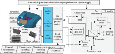
The one-dimensional system simulation model can study the matching relationship between different components and the impact on the overall performance of the system from a system perspective. The 3D model focuses on the analysis and optimization of the details of the research object [113]. Liu et al. [114] proposed a one-dimensional/three-dimensional co-simulation framework for the thermal management system in the engine compartment of a pure electric vehicle as shown in Figure 7 in view of the characteristics of many heat exchange components in the engine compartment of pure electric vehicles, and the heat exchange process affects each other. The algorithm makes the one-dimensional air-conditioning system and power system and the three-dimensional engine compartment condenser model, battery radiator and motor radiator to perform joint calculation, and simulates and studies the air-conditioning load change and the condenser, battery radiator and motor heat dissipation in the integrated thermal management system. The mutual influence between the arrangement positions of the devices. The results show that when the condenser is placed in front of the motor and battery radiator, the cooling effect of the motor and battery cooling system will decrease with the increase of air conditioning load. When the condenser is placed behind the motor and battery radiator, the load change of the air conditioning system has little effect on the cooling performance of the power system. This study methodology offers a fresh concept for the ideal configuration and administration of the integrated thermal system of electric vehicles.
Figure 7. Framework of 1D/3D co-simulation in EV
From the aforementioned, it can be observed that the one-dimensional system simulation model may optimize the integrated thermal management system of electric cars' control strategy from a broad standpoint, enhancing its functionality. However, the integrated thermal management system's core heat exchange components' three-dimensional structure, including their shape, size, and location, cannot be optimized using simply the one-dimensional simulation model.
The integrated thermal management systems in electric vehicles include a variety of heat sources, several temperature zones, and varying temperatures. Several thermal management subsystems are now evaluating the battery thermal management system's performance utilizing a variety of performance assessment indicators, such as battery temperature and temperature difference. The passenger compartment thermal management system is evaluated using the performance coefficient COP, which measures the benefit (cooling or heating) to cost (power consumption) ratio, while the thermal management of the motor drive system is evaluated using the motor temperature. The objectives for thermal management listed above conflict while they are being achieved. Realistic factors like procedure, cost, quality, strength, and sealing are not included, and there is no standardized, all-encompassing system of evaluation.
The integrated thermal management system for electric cars is a thermodynamic system, and the thermodynamic technique may be used to optimize the performance from the viewpoint of the system. The performance of an integrated thermal management system for an extended-range electric vehicle was examined in reference [115] using the second law of thermodynamics. Each component in the thermal management loop was optimized by looking at the system's energy efficiency, which increased the performance of the integrated thermal management system. The findings of the study indicate that the primary causes of the irreversibility of the integrated thermal management system are heat exchanges between the system and its surroundings and fluid friction inside system components. Afzal et al. [116] created an integrated thermal management system with car air conditioners, batteries, and parallel evaporators installed in the air conditioner system to supply phase change materials. Octadecane, a phase change material, was employed as the cooling medium for the batteries. Exergy research reveals that the heat exchanger has the lowest exergy efficiency compared to other system components, with a 31% exergy efficiency for the entire system and a maximum exergy loss rate of 0.4 kW. Based on this, the environmental advantages of the total integrated thermal management are also examined. It is highlighted that increasing the system's energy efficiency can lower greenhouse gas emissions and increase the sustainability of the system. The system's highest exergy efficiency and minimal cost rate are 34.5% and 1.38 $h-1, respectively, according to the findings of the genetic algorithm's optimization of the system with these two characteristics.
There is currently few research on the comprehensive evaluation system of the integrated thermal management system of electric cars; nevertheless, this comprehensive evaluation system may enable the deployment of this system in real-world models and act as a roadmap for its evolution. In the current study, which focuses primarily on the performance optimization of a single system, practical considerations from the vehicle level are seldom incorporated in order to completely examine the performance of the integrated thermal management system. Future study should be based on the principles of thermodynamics and should also examine applications in order to create a full and standardized assessment system.
Table 1. Comparison of thermal characteristics of various state-of-the-art methods
|
Ref. |
Coupling method |
Charge/discharge rate |
$T_{1 \text { max }} ; \Delta T_{1 \text { max }}\left({ }^{\circ} \mathrm{C}\right)$ |
$T_{2 \max } ; \Delta T_{2 \max }\left({ }^{\circ} \mathrm{C}\right)$ |
|
[64] |
Liquid cooling |
5 C |
52.9; 7.9 |
44.0; 3.2 |
|
[68] |
Liquid cooling |
0.9 C |
32; 1.2 |
30.0; 0.6 |
|
[69] |
Liquid cooling |
12.5 W |
60; - |
45.1; - |
|
[73] |
Liquid cooling |
2 C |
50.0; 4.1 |
42.0; 1.2 |
|
[88] |
Liquid cooling |
3 C |
45.10; - |
41.1; 4.0 |
|
[94] |
Liquid cooling |
2 C |
39.00; - |
25.0; 1.0 |
|
[107] |
Air cooling |
1 C |
- |
25.6; - |
|
[108] |
Air cooling |
5 W |
46.6; - |
35.8; - |
|
[109] |
Air cooling |
2 C |
- |
51.9; 2.6 |
|
[110] |
Air cooling |
2 C |
- |
37.0 |
|
[110] |
Air cooling |
2.5 W |
43.0; - |
26.0 |
In order to give further insight of the battery thermal management models, Table 1 compares various important parameters of state-of-the-art methods. It shows the experimental results of the temperature difference before and after the BTM system after coupling liquid cooling or air cooling. When the PCM is coupled under the existing liquid cooling or air cooling heat dissipation, the maximum temperature drop of the system is 8.9~10.8℃, which is a large drop and the difference between different PCMs Not obvious. Compared with using PCM alone, the maximum temperature of the coupled liquid cooling system reaches 25~45.1℃, a drop of about 2~14℃; the maximum temperature of the coupled air cooling system is 25.6~51.9℃, and the drop range is between 4.9~17℃. Larger, indicating that the liquid pipeline, flow rate or air flow path have a significant impact on heat dissipation. Even at a high discharge rate of 5 C, the coupling system meets the maximum temperature below 50℃, and the maximum temperature difference under different working conditions is only 4℃, and the energy consumption is also reduced to match the thermal management requirements. Scholars conducted experiments on innovative fluid channels such as honeycomb type, embedded type, and side plate type, optimized the airflow organization on the surface of the battery, and tried to change the working medium in the tube and the tube diameter enhancement system, which has uniform heat dissipation characteristics at high discharge rates. Valuable suggestions are put forward for the innovation of vehicle liquid cooling/air cooling structure.
Temperature has a significant impact on how well electric cars function, thus creating an effective integrated thermal management system for them is crucial to their further growth. The integrated thermal management system of electric cars still has the following issues that demand immediate attention despite the fact that the standards for thermal management systems in electric vehicles have improved:
(1) The integrated thermal management system's design is based on the battery heat generation model, the cooling and heating load calculation model, and the heat generation model of the motor drive system. To increase the predictive capability of the models and offer theoretical support for equipment optimization design and engineering applications, it is necessary to further investigate the mechanisms behind the various heat generation models.
(2) Electric vehicle integrated thermal management systems should progress in the directions of lightness, compactness, and integration. The performance optimization of a single thermal management system is the primary emphasis of current thermal management research, which ignores the interdependence of the thermal management subsystems. To improve the performance of the integrated thermal management system of electric vehicles, further study should make use of advanced thermal management techniques like heat pump technology, heat pipe technology, and direct evaporative cooling battery packs. These techniques take into account the coupling relationship between the various thermal management subsystems from the integrated system level.
(3) Each component in the integrated thermal management system has varying needs depending on the operating circumstances of electric cars. In order to meet the thermal management needs of electric vehicles under challenging and variable operating conditions, further research can be done using the 1D/3D co-simulation method to develop targeted operation control strategies and optimal control methods for various integrated thermal management systems.
(4) The current research ignores the effect of multiple elements such as process, cost, quality, strength, sealing, etc., lack of standardization and communication in favor of increasing the performance index of a single thermal management system. To encourage the development of integrated thermal management systems for electric cars, more research should completely take into account the restrictions between various components in the system, establish standardized test procedures, and offer corresponding comprehensive assessment indicators.
|
A |
amper |
|
B |
magnetic flux, Wb.m−2 |
|
BTMS |
Battery Thermal Management System |
|
c |
specific heat capacity of battery, J·(kg·K)-1 |
|
C |
specific heat capacity of current collector, J·(kg·K)-1 |
|
COP |
Coefficient of Performance |
|
EV |
Electric Vehicle |
|
EVTMS |
Electric Vehicle Thermal Management System |
|
f |
frequency, Hz |
|
HVAC |
Heating Ventilation and Air Conditioning |
|
h |
thicknesses, m |
|
I |
current, A |
|
J |
current density, A.m−3 |
|
k |
Thermal conductivity of electrode sheet, W·(m·K)−1 |
|
kh |
hysteresis loss coefficient |
|
ke |
eddy current loss coefficient |
|
Pcu |
copper loss, W |
|
PCM |
Phase Change Materials |
|
PTC |
Positive Temperature Coefficient |
|
PID |
Proportional Integral Derivative |
|
PCCR |
Percentage of Cooling Capacity Reduction |
|
$\dot{\mathrm{q}}$ |
heat production rate, W.m-3 |
|
Q |
total heat load, W |
|
R |
resistance, Ω |
|
S |
area, m2 |
|
T |
temperature, K |
|
U0 |
open circuit voltage, V |
|
U |
working voltage, V |
|
V |
Volt |
|
Vb |
battery volume, m3 |
|
Greek symbols |
|
|
$\Delta \emptyset$ |
potential difference, V |
|
σ |
conductivity, S.m−1 |
|
τ |
time, s |
|
λ |
thermal conductivity of battery cell, W·(m·K)-1 |
|
ρ |
density, kg.m-3 |
|
Subscripts |
|
|
n |
negative |
|
p |
positive |
|
x,y,z |
cartesian coordinates |
[1] Vencheh, A., Tan, Y., Wanke, P., Loghmanian, S. (2021). Air pollution assessment in china: a novel group multiple criteria decision making model under uncertain information. Sustainability, 13(4): 1-18. https://doi.org/10.3390/su13041686
[2] Sanguesa, J., Sanz, V., Garrido, P., Martinez, F., Barja, J. (2021). A review on electric vehicles: technologies and challenges. Smart Cities, 4(1): 1-24. https://doi.org/10.3390/smartcities4010022
[3] Ravi, S., Aziz, M. (2022). Utilization of electric vehicles for vehicle-to-grid services: progress and perspectives. Energies, 15(2): 1-19. https://doi.org/10.3390/en15020589
[4] Che, Y., Foley, A., Gindy, M., Lin, X., Hu, X., Pecht, M. (2021). Joint estimation of inconsistency and state of health for series battery packs. Automotive Innovation, 4(2): 103-116. https://doi.org/10.1007/S42154-020-00128-8
[5] Gholami, J., Barzoki, M. (2021). Electrochemical modeling and parameter sensitivity of lithium-ion battery at low temperature. Journal of Energy Storage, 43(5): 1021-1043. https://doi.org/10.1016/j.est.2021.103189
[6] Wu, X., Wang, W., Sun, Y., Wen, T., Chen, J., Du, J. (2020). Study on the capacity fading effect of low-rate charging on lithium-ion batteries in low-temperature environment. World Electric Vehicle Journal, 11(3): 1-16. https://doi.org/10.3390/wevj11030055
[7] Zhang, N., Deng, T., Zhang, S., Wang, C., Chen, L., Wang, C., Fan, X. (2022). Critical review on low-temperature li-ion/metal batteries. Advances Materials, 34(15): 2175-2184. https://doi.org/10.1002/adma.202107899
[8] Alipour, M., Ziebert, C., Conte, F., Kizilel, R. (2020). A review on temperature-dependent electrochemical properties, aging, and performance of lithium-ion cells. Batteries, 6(3): 1-15. https://doi.org/10.3390/batteries6030035
[9] Leach, F., Kalghatgi, G., Stone, R., Miles, P. (2020). The scope for improving the efficiency and environmental impact of internal combustion engines. Transportation Engineering, 1(4): 1071-1083. https://doi.org/10.1016/j.treng.2020.100005
[10] Tan L., Yuan, Y. (2022). Computational fluid dynamics simulation and performance optimization of an electrical vehicle air-conditioning system. Alexandria Engineering Journal, 61(1): 315-328. https://doi.org/10.1016/j.aej.2021.05.001
[11] Idoko, H., Akuru, U., Wang, R., Popoola, O. (2022). Potentials of brushless stator-mounted machines in electric vehicle drives – a literature review. World Electric Vehicle Journal, 13(5): 1-18. https://doi.org/10.3390/wevj13050093
[12] Pop, E., Sinha, S., Goodson, K. (2006). Heat generation and transport in nanometer-scale transistors. Proceedings of the IEEE, 94(8): 1587-1601. https://doi.org/10.1109/JPROC.2006.879794
[13] Mahajan, R., Chiu, C., Chrysler, G. (2006). Cooling a microprocessor chip. Proceedings of the IEEE, 94(8): 1476-1486. https://doi.org/10.1109/JPROC.2006.879800
[14] Hamann, H., Weger, A., Lacey, J., Hu, Z., Bose, P., Cohen, E., Wakil, J. (2007). Hotspot-limited microprocessors: direct temperature and power distribution measurements. IEEE Journal of Solid-State Circuits, 42(1): 56-65. https://doi.org/10.1109/JSSC.2006.885064
[15] Wagner, J., Ghone, M., Dawson, D., Marotta, E. (2002). Coolant flow control strategies for automotive thermal management systems. Warrendale, PA, USA: SAE International. https://doi.org/10.4271/2002-01-0713
[16] Mallik, S., Ekere, N., Best, C., Bahatti, R. (2011). Investigation of thermal management materials for automotive electronic control units. Applied Thermar Engineering, 31(2): 355-362. https://doi.org/10.1016/j.applthermaleng.2010.09.023
[17] Marshall, G., Mahony, C., Rhodes, M., Daniewics, S., Tsolas, N., Thompson S. (2019). Thermal management of vehicles cabins, external surfaces, and onboard electronics: an overview. Engineering, 5(5): 954-969. https://doi.org/10.1016/j.eng.2019.02.009
[18] Snyder, G., Toberer E. (2008). Complex thermoelectric materials. Nature Materials, 7(2): 105-114. https://doi.org/10.1038/nmat2090
[19] Lajunen, A., Hadden, T., Hirmiz, R., Cotton, J., Emadi, A., (2017). Thermal energy storage for increasing heating performance and efficiency in electric vehicles. 2017 IEEE Transportation Electrification Conference and Expo (ITEC), Harbin, pp. 95-100. https://doi.org/10.1109/ITEC.2017.7993253
[20] Leong, K., Saidur, R., Kazi, S., Mamun, A. (2010). Performance investigation of an automotive car radiator operated with nanofluid-based coolants (nanofluid as a coolant in a radiator). Applied Thermal Engineering, 30(17): 2685-2692. https://doi.org/10.1016/j.applthermaleng.2010.07.019
[21] Kim, E., Shin, K., Lee, J. (2014). Real-time battery thermal management for electric vehicles. ACM/IEEE International Conference on Cyber-Physical Systems (ICCPS), Berlin, Germany, pp. 72-83. https://doi.org/10.1109/ICCPS.2014.6843712
[22] Kim, E., Lee, J., Shin, K. (2015). Modeling and real-time scheduling of large-scale batteries for maximizing performance. IEEE Real-Time Systems Symposium, San Antonio, Texas, USA, pp. 33-42. https://doi.org/10.1109/RTSS.2015.11
[23] Lopez, J., Ocampo, C., Alvarez, J., Moreno, M., Ruiz, R., Kalmus, J., Graeber, M., Lux, G. (2017). Nonlinear model predictive control for thermal management in plug-in hybrid electric vehicles. IEEE Transactions on Vehicular Technology, 66(5): 3632-3644. https://doi.org/10.1109/TVT.2016.2597242
[24] Yang, Z., Zhou, L., Luo, W., Wan J., Dai J., Han, X., Fu, K., Henderson, D., Yang, B., Hu, L. (2016). Thermally conductive, dielectric PCM-boron nitride nanosheet composites for efficient electronic system thermal management. Nanoscale, 8(46): 19326-19333. https://doi.org/10.1039/C6NR07357C
[25] Prasher, R. (2006). Thermal interface materials: historical perspective, status, and future directions. Proceedings of the IEEE, 94(8): 1571-1586. https://doi.org/10.1109/JPROC.2006.879796
[26] Lemmon, E., Jacobsen, R.T. (2004). Viscosity and thermal conductivity equations for nitrogen, oxygen, argon, and air. International Journal of Thermophysics, 25(1): 21-69. https://doi.org/10.1023/B:IJOT.0000022327.04529.f3
[27] Sarvar, F., Whalley, D., Conway, P. (2006). Thermal interface materials-a review of the state of the art. 1st Electronic System Integration Technology Conference, Dresden, Germany, pp. 1292-1302. https://doi.org/10.1109/ESTC.2006.280178
[28] Due, J., Robinson, A. (2013). Reliability of thermal interface materials: A review. Applied Thermal Engineering, 50(1): 455-463. https://doi.org/10.1016/j.applthermaleng.2012.06.013
[29] Hansson, J., Nilsson, T., Ye, L., Liu, J. (2017). Novel nanostructured thermal interface materials: A review. International Materials Reviews, 37: 1-24. https://doi.org/10.1080/09506608.2017.1301014
[30] Hu, Y., Du, G., Chen, N. (2016). A novel approach for Al2O3/epoxy composites with high strength and thermal conductivity. Composites Science and Technology, 124: 36-43. https://doi.org/10.1016/j.compscitech.2016.01.010
[31] Yu, H., Li, L., Kido, T., Xi, G., Xu, G., Guo, F. (2012). Thermal and insulating properties of epoxy/aluminum nitride composites used for thermal interface material. Journal of Applied Polymer Science, 124(1): 669-677. https://doi.org/10.1002/app.35016
[32] Xing, W., Xu, Y., Song, C., Deng, T. (2022). Recent Advances in Thermal Interface Materials for Thermal Management of High-Power Electronics. Nanomaterials, 12(19): 1-34. https://doi.org/10.3390/nano12193365
[33] Ren, J., Li, Q., Yan, L., Jia, L., Huang, X., Zhao, L, Ran, Q., Fu, M. (2020). Enhanced thermal conductivity of epoxy composites by introducing graphene and boron nitride nanosheets hybrid nanoparticles. Materials and Design, 191(8): 887-905. https://doi.org/10.1016/j.matdes.2020.108663
[34] Guo, X., Cheng, S., Cai, W., Zhang, Y., Zhang, X. (2021). A review of carbon-based thermal interface materials: mechanism, thermal measurements and thermal properties. Materials and Design, 209(1): 1099-1114. https://doi.org/10.1016/j.matdes.2021.109936
[35] Feng, X., Ouyang, M., Liu, X. (2018). Thermal runaway mechanism of lithium ion battery for electric vehicles: a review. Energy Storage Materials, 10: 246-267.
[36] Ren, D., Hsh, H., Li, R. (2019). A comparative investigation of aging effects on thermal runaway behavior of lithium-ion batteries. eTransportation, 2: 1-14.
[37] Cen, J., Jiang, F. (2020). Li-ion power battery temperature control by a battery thermal management and vehicle cabin air conditioning integrated system. Energy for Sustainable Development, 57: 141-148.
[38] Lei, Z., Zhang, L. (2018). Improving temperature uniformity of a lithium-ion battery by intermittent heating method in cold climate. International Journal of Heat and Mass Transfer, 121: 275-281.
[39] Vikram, S., Vashisht, S., Rakshit, D. (2022). Performance analysis of liquid-based battery thermal management system for electric vehicles during discharge under drive cycles. Journal of Energy Storage, 55(4): 1057-1071.
[40] Liaw, B., Roth, E., Jungst, R. (2003). Correlation of Arrhenius behaviors in power and capacity fades with cell impedance and heat generation in cylindrical lithium-ion cells. Journal of Power Sources, 121: 874-886.
[41] Zaree, M., Dinner, I., Rosen, M. (2017). Novel thermal management system using boiling cooling for high-powered lithium battery packs for hybrid electric vehicles. Journal of Power Sources, 363: 291-303.
[42] Smith, J., Hinterberger, M., Schneider, C. (2016). Energy savings and increased electric vehicle rang through improved battery thermal management. Applied Thermal Engineering, 101: 647-656.
[43] Zhang, T., Qu, Z., Wang, G. (2017). Investigation on the promotion of temperature uniformity for the designed battery pack with liquid flow cooling. Applied Thermal Engineering, 116: 655-662.
[44] Yang, Y., Lu, Y., Du, X. (2019). Pre-cooling of air by water spray evaporation to improve thermal performance of lithium battery pack. Applied Thermal Engineering, 163: 1144-1161.
[45] Zhang, M., Li, Y., Rao, E. (2016). Thermal performance of lithium-ion battery thermal management system by using mini-channel cooling. Energy Conversion and Management, 126: 622-631.
[46] Rao, E., Wang, Q., Huang, C. (2016). Investigation of the thermal performance of phase change material/mini-channel coupled battery thermal management system. Applied Energy, 164: 659-669.
[47] Huang, R., Li, Z., Hong, W. (2020). Experimental and numerical study of PCM thermophysical parameters on lithium-ion battery thermal management. Energy Reports, 6: 8-19.
[48] Liang, J., Gan, Y., Li, Y. (2019). Thermal and electrochemical performance of a serially connected battery module using a heat pipe-based thermal management system under different coolant temperatures. Energy, 189: 1754-1769.
[49] Tian, Z, Gu, B. (2019). Analyzes of an integrated thermal management system for electric vehicles. International Journal of Energy Research, 43(11): 5788-5802.
[50] Tian, Z., Gan, W., Zhang, X. (2018). Investigation on an integrated thermal management system with battery cooling and motor waste heat recovery for electric vehicle. Applied Thermal Engineering, 136: 16-27.
[51] Tian, Z., Gu, B., Zu, H. (2020). Performance evaluation of an electric vehicle thermal management system with waste heat recovery. Applied Thermal Engineering, 169: 848-862.
[52] Hamut, H., Dinner, I., Naterer, G. (2014). Exergo environmental analysis of hybrid electric vehicle thermal management systems. Journal of Cleaner Production, 67: 187-196.
[53] Chu, A., Yuan, Y., Zhu, J., Lu, X., Zhou, C. (2020). The design and investigation of a cooling system for a high power Ni-MH battery pack in hybrid electric vehicles. Applied Sciences, 10(5): 1-19.
[54] Wei, C., Hofman, T., Caarls, E., Iperen, R. (2019). Integrated energy and thermal management for electrified powertrains. Energies, 12(11): 1-18.
[55] Wang, Z., Huang, L., He, F. (2022). Design and analysis of electric vehicle thermal management system based on refrigerant-direct cooling and hearing batteries. Journal of Energy Storage, 51(2): 4318-4332.
[56] Cen, J., Li, Z., Jiang, F. (2018). Experimental investigation on using the electric vehicle air conditioning system for lithium-ion battery thermal management. Energy and Sustainable Development, 45: 88-95.
[57] Shen, M., Zu, L. (2020). System simulation on refrigerator-based battery thermal management technology for electric vehicles. Energy Conversion and Management, 203: 176-192.
[58] Han, X., Zou, H., Tian, C. (2019). Numerical study on the heating performance of a novel integrated thermal management system for the electric bus. Energy, 186: 1158-1169.
[59] Madani, S., Schaltz, E., Kaer, S. (2020). Thermal analysis of cold plate with different configurations for thermal management of a lithium-ion battery. Batteries, 6(1): 1-18. https://doi.org/10.3390/batteries6010017
[60] Zeng, X., Men, Z., Deng, F., Chen, C. (2022). Optimization of the heat dissipation performance of a lithium-ion battery thermal management system with cpcm/lithium cooling. Materials, 15(11): 1-19. https://doi.org/10.3390/ma15113835
[61] Chiew, J., Chin, C., Toh, W. (2019). A pseudo three-dimensional electrochemical-thermal model of a cylindrical LiFePO4/graphite battery. Applied Thermal Engineering, 147(3): 450-464. https://doi.org/10.1016/j.applthermaleng.2018.10.108
[62] Katrasnik, T., Mele, I., Zelic, K. (2021). Multi-scale modelling of lithium-ion batteries: from transport phenomena to the outbreak of the thermal runaway. Energy Conversion Management, 236(3): 1467-1478. https://doi.org/10.1016/j.enconman.2021.114036
[63] Liang, J., Gan, Y., Song, W. (2020). Thermal-electrochemical simulation of electrochemical characteristics and temperature difference for a battery module under two-stage fast charging. Journal of Energy Storage, 29(6): 307-318. https://doi.org/10.1016/j.est.2020.101307
[64] He, C., Yue, Q., Wu, M., Chen, Q., Zhao, T. (2021). A 3D electrochemical-thermal coupled model for electrochemical and thermal analysis of pouch-type lithium-ion batteries. International Journal of Heat and Mass Transfer, 181(4): 855-864. https://doi.org/10.1016/j.ijheatmasstransfer.2021.121855
[65] Lyu, Y., Siddique, A., Majid, S., Biglarbegian, M., Gadsden, S., Mahmud, S. (2019). Electric vehicle battery thermal management system with thermoelectric cooling. Energy Reports, 5(1): 822-827. https://doi.org/10.1016/j.egyr.2019.06.016
[66] Shojaei, S., McGordon, A., Robinson, S. (2017). Developing a model for analysis of the cooling loads of a hybrid electric vehicle by using co-simulations of verified submodels. Journal of Automobile Engineering, 232(6): 766-784. https://doi.org/10.1177/0954407017707099
[67] Tao, Y., Yang, M., Qian, B., Wu, F., Wang, T. (2019). Numerical and experimental study on ventilation panel models in a subway passenger compartment. Engineering Journal, 5(2): 329-336. https://doi.org/10.1016/j.eng.2018.12.007
[68] Miri, I., Fotouhi, A., Ewin, N. (2021). Electric vehicle energy consumption modelling and estimation – a case study. International Journal of Energy Research, 45(1): 501-520. https://doi.org/10.1002/er.5700
[69] Sotelo, D., Licea, M., Vargas, I., Olivarez, J., Gutierrez, A., Pinal, F. (2022). Power losses models for magnetic cores: a review. Micromachines, 13(3): 1-19. https://doi.org/10.3390/mi13030418
[70] Chen, K., Li, Z., Chen, Y. (2017). Design of parallel air-cooled battery thermal management system through numerical study. Energies Journal, 10(10): 1-16. https://doi.org/10.3390/en10101677
[71] Peng, X., Chen S., Garg A., Bao N., Panda, B. (2019). A review of the estimation and heating methods for lithium-ion batteries pack at the cold environment. Energy Science and Engineering, 7(3): 645-662. https://doi.org/10.1002/ese3.279
[72] Kannan, C., Vignesh, R., Karthick, C., Ashok, B. (2021). Critical review towards thermal management systems of lithium-ion batteries in electric vehicles with its electronic control unit assessment tools. Journal of Automobile Engineering, 235(7): 1783–1807. https://doi.org/10.1177/0954407020982865
[73] Shetty, D., Venugopel, V., Pradeep, R., Zuber, M., Badruddin, I., Kini, C. (2021). Computational flow analysis of different streamline cooling plates for thermal management of lithium-ion battery. Cogent Engineering, 9(1): 933-944. https://doi.org/10.1080/23311916.2022.2048996
[74] Kim, J., Oh, J., Lee, H. (2019). Review on battery thermal management system for electric vehicles,” Applied Thermal Engineering, 149(5): 459-467. https://doi.org/10.1016/j.applthermaleng.2018.12.020
[75] Wang, C., Zhang, G., Meng, L. (2017). Liquid cooling based on thermal silica plate for battery thermal management system. International Journal of Energy Research, 41(15): 2468-2483. https://doi.org/10.1002/er.3801
[76] Falcone, M., Volo, E., Hellany, A., Rossi, C., Pulvirenti, B. (2021). Lithium-ion battery thermal management systems: a survey and new cfd results. Batteries Journal, 7(4): 1–18. https://doi.org/10.3390/batteries7040086
[77] Mahamud, R., Park, C. (2022). Theory and practices of li-ion battery thermal management for electric and hybrid electric vehicles. Energies Journal, 15(11): 1-17. https://doi.org/10.3390/en15113930
[78] Tan, T., Guo, C., Su, H., Guo, C., Jiang, Y. (2021). Experimental study on u-shape flat thermosiphon for thermal management of power battery. Journal of Mechanical Science and Technology, 35(3): 4193-4200. https://doi.org/10.1007/S12206-021-0831-6
[79] Lv, Y, Situ, W., Yang, X. (2018). A novel nanosilica-enhanced phase change material with anti-leakage and anti-volumen-changes properties for battery thermal management. Energy Conversion and Management, 163(4): 932-944. https://doi.org/10.1016/j.enconman.2018.02.061
[80] Weng, J., He, Y., Ouyang, D. (2019). Thermal performance of pcm and branch-structured fins for cylindrical power battery in a high-temperature environment. Energy Conversion and Management, 200(8): 1115-1126. https://doi.org/10.1016/j.enconman.2019.112106
[81] Ranjbaran, Y., Haghparast, S., Shojaeefard, M., Molaeimanesh, G. (2020). Numerical evaluation of a thermal management system consisting pcm and porous metal foam for li-ion batteries. Journal of Thermal Analysis and calorimetry, 141(5): 1717-1739. https://doi.org/10.1007/S10973-019-08989-W
[82] Jilite, R., Kumar, R., Ahmadi, M. (2019). Battery thermal management system employing phase change material with cell-to-cell air cooling. Applied Thermal Engineering, 161(3): 3678-3687. https://doi.org/10.1016/j.applthermaleng.2019.114199
[83] Wazeer, A., Das, A., Abeykoon, C., Sinha, A., Karmakar, A. (2022). Phase change materials for battery thermal management of electric and hybrid vehicles: A review. Energy Nexus, 7(8): 9832-9845. https://doi.org/10.1016/j.nexus.2022.100131
[84] Chopra, K., Tyagi, V., Pathak, A. (2019). Experimental performance evaluation of a novel designed phase change material integrated manifold heat pipe evacuated tube solar collector system. Energy Conversion and Management, 198(7): 9342-9356. https://doi.org/10.1016/j.enconman.2019.111896
[85] Chen, G., Tang, Y., Wan, Z. (2019). Heat transfer characteristics of an ultra-thin flat plate heat pipe with surface-functional wicks for cooling electronics. International Communications in Heat and Mass Transfer, 100(5): 12-19. https://doi.org/10.1016/j.icheatmasstransfer.2018.10.011
[86] Zhou, W., Li, Y., Chen, Z. (2019). Effect of the passage area ratio of liquid to vapor on an ultra-thin flattened heat pipe. Applied Thermal Engineering, 162(3): 6732-6744. https://doi.org/10.1016/j.applthermaleng.2019.114215
[87] Wang, X., Wright, E., Liu, Z., Gao, N., Li, Y. (2022). Development of a novel artificial neural network model for closed pulsating heat pipe with water and aqueous solutions. Asia-Pacific Journal of Chemical Engineering, 17(1): 2719-2734. https://doi.org/10.1002/apj.2719
[88] Ye, X., Zhao, Y., Quan, Z. (2018). Experimental study on heat dissipation for lithium-ion battery based on micro heat pipe array. Applied Thermal Engineering, 130(5): 74-82. https://doi.org/10.1016/j.applthermaleng.2017.10.141
[89] Liang, J., Guan, Y., Li, Y. (2018). Investigation on thermal performance of a battery thermal management system using heat pipe under different ambient temperatures. Energy Conversion and Management, 155(1): 755-766. https://doi.org/10.1016/j.enconman.2017.10.063
[90] Jouhara, H., Delpech, B., Bennett, R., Chauhan, A., Khordehgah, N., Serey, N, Lester, S. (2021). Heat pipe based battery thermal management: evaluating the potential of two novel battery pack integrations. International Journal of Thermofluids, 12(6): 6892-6906. https://doi.org/10.1016/j.ijft.2021.100115
[91] Wang, J., Gan, Y., Liang, J. (2019). Sensitivity analysis of factors influencing a heat pipe-based thermal management system for a battery module with cylindrical cells. Applied Thermal Engineering, 151(2): 151-164. https://doi.org/10.1016/j.applthermaleng.2019.02.036
[92] Liang, J., Gan, Y., Li, Y. (2019). Thermal and electrochemical performance of a serially connected battery module using a heat pipe-based thermal management system under different coolant temperatures. Energy Journal, 189(4): 1153-1169. https://doi.org/10.1016/j.energy.2019.116233
[93] Gan, Y., Wang, J., Liang, J. (2020). Development of thermal equivalent circuit model of heat pipe-based thermal management system for a battery module with cylindrical cells. Applied Thermal Engineering, 164(5): 4534-4546. https://doi.org/10.1016/j.applthermaleng.2019.114523
[94] Jiang, Z., Qu, Z. (2019). Lithium-ion battery thermal management using heath pipe and phase change material during discharge-charge cycle: A comprehensive numerical study. Applied Energy, 242(7): 5632-5644. https://doi.org/10.1016/j.apenergy.2019.03.043
[95] Zhao, C., Li, Y., Yang, Y., Wan, S., Yu, F. (2021) Research on electric vehicle rang under cold condition. Advances in Mechanical Engineering, 14(3): 5683-5694. https://doi.org/10.1177/16878132221087083
[96] Wei, Y., Liu, S., Yu, J. (2022). A study on performance characteristics of vapor injection heat pump cycle with indirect heat recovery. Thermal Science and Engineering Progress, 34(1): 1037-1048. https://doi.org/10.1016/j.tsep.2022.101437
[97] Lee, M., Garud, K., Jeon, H., Lee, H. (2020). A study on performance characteristics of a heat pump system with high-pressure side chiller for light-duty commercial electric vehicles. Symmetry, 12(8): 1-18. https://doi.org/10.3390/sym12081237
[98] Yu, B., Luo, Y., Chu, W. (2021). Analysis on frosting of heat exchanger and numerical simulation of heat transfer characteristics using BP neural network learning algorithm. PLoS One Journal, 16(9): 1-22. https://doi.org/10.1371/journal.pone.0256836
[99] Zhang, Z., Li, W., Shi, J. (2016). A study on electric vehicle heat pump systems in cold climates. Energies Journal, 9(11): 881-893. https://doi.org/10.3390/en9110881
[100] Liu, C., Zhang, Y., Gao, T. (2016). Performance evaluation of propane heat pump system for electric vehicle in cold climate. International Journal of Refrigeration, 95(4): 843-855. https://doi.org/10.1016/j.ijrefrig.2018.08.020
[101] Yilmazoglu, M. (2016). Experimental and numerical investigation of a prototype thermoelectric heating and cooling unit. Energy and Buildings, 113(7): 873-884. https://doi.org/10.1016/j.enbuild.2015.12.046
[102] Hwang, S., Garud, K., Seo, J., Lee, M. (2022). Heat flow characteristics of ferrofluid in magnetic field patterns for electric vehicle power electronics cooling. Symmetry Journal, 14(5): 1-18. https://doi.org/10.3390/sym14051063
[103] Zhao, W., Zhang, T., Kildahl, H., Ding, Y. (2022). Mobile energy recovery and storage: multiple energy-powered EVs and refueling stations. Energy Journal, 257(8): 697-708. https://doi.org/10.1016/j.energy.2022.124697
[104] Jiang, L., Wang, R., Li, J. (2018). Performance analysis on a novel sorption air conditioner for electric vehicles. Energy Conversion and Management, 156(5): 778-789. https://doi.org/10.1016/j.enconman.2017.11.077
[105] Lindh, P., Petrov, I., Immonen, P., Pyrhonen, J., Niemela, M., Anttila, J., Paakkinen, M., Scherman, E. (2019). Performance of a direct-liquid-cooled motor in an electric bus under different load cycles. IEEE Access, 7: 86897-86905. https://doi.org/10.1109/ACCESS.2019.2925711
[106] Zhang, C., Zhang, X., Zhao, F., Gerada, D., Li, L. (2022). Improvements on permanent magnet synchronous motor by integrating heat pipes into winding for solar unmanned aerial vehicle. Green Energy and Intelligent Transportation, 1(1): 898-909. https://doi.org/10.1016/j.geits.2022.100011
[107] Youssef, R., Hosen, M., He, J., Saadi, M., Mierlo, J., Berecibar, M. (2022). Novel design optimization for passive cooling PCM assisted battery thermal management system in electric vehicles. Case Studies in Thermal Engineering, 32(7): 1759-1768. https://doi.org/10.1016/j.csite.2022.101896
[108] Murugan, M., Saravanan, A., Elumalai, P., Murali, G., Dhineshbabu, N., Kumar, P., Afzal, A. (2022). Thermal management system of lithium-ion battery packs for electric vehicles: an insight based on bibliometric study. Journal of Energy Storage, 52(1): 4723-4731. https://doi.org/10.1016/j.est.2022.104723
[109] Tian, Z., Gan, W., Zhang, X. (2018). Investigation on an integrated thermal management system with battery cooling and motor waste heat recovery for electric vehicle. Applied Thermal Engineering, 136(16): 9973-9987. https://doi.org/10.1016/j.applthermaleng.2018.02.093
[110] Tian, Z., Gu, B. (2019). Analysis of an integrated thermal management system for electric vehicles. International Journal of Energy Research, 43(11): 5788-5802. https://doi.org/10.1002/er.4679
[111] Cen, J., Li, Z., Jiang, F. (2018). Experimental investigations on using the electric vehicle air conditioning system for lithium-ion battery thermal management. Energy for Sustainable Development, 45(4): 88-95. https://doi.org/10.1016/j.esd.2018.05.005
[112] Schaut, S., Arnold, E., Sawodny, O. (2021). Predictive thermal management for an electric vehicle powertrain. IEEE Transaction on Intelligent Vehicles, 4(1): 944-956. https://doi.org/10.1109/TIV.2021.3131944
[113] Zhang, Q., Xu, L., Li, J. (2018). Performance prediction of proton exchange membrane fuel cell engine thermal management system using 1D and 3D integrating numerical simulation. International Journal of Hydrogen Energy, 43(3): 1736-1754. https://doi.org/10.1016/j.ijhydene.2017.10.088
[114] Liu, Y., Gao, Q., Zhang, T. (2020). Exploration of interactive thermal influence characteristics of power and air conditioning system based on 1D/3D coupling calculation in electric vehicle underhood. Applied Thermal Engineering, 167(5): 717-728. https://doi.org/10.1016/j.applthermaleng.2019.114717
[115] Kim, T., Ryu, M., Park, S., Kim, K., Kim, H., Park, S. (2019). Performance estimation of new vehicle thermal management system for an unmanned military ground vehicle using integrated simulation model. International Journal of Automotive Technology, 20(6): 429-444. https://doi.org/10.1007/S12239-019-0041-8
[116] Afzal, H., Samee, A., Soudagar, M., Akram, N., Mujtaba, M., Jilte, R., Islam, M., Agbulut, U., Saleel, C. (2022). Optimization of thermal and structural design in lithium-ion batteries to obtain energy efficient battery thermal management system: a critical review. Archives of Computational Methods in Engineering, 29(8): 129-194. https://doi.org/10.1007/S11831-021-09571-0