Mohammed Jameel Alsalhy![]() | Sarah Rabeea Nashee*
| Sarah Rabeea Nashee*![]() | Ahmed A. Ouda
| Ahmed A. Ouda![]()
© 2025 The authors. This article is published by IIETA and is licensed under the CC BY 4.0 license (http://creativecommons.org/licenses/by/4.0/).
OPEN ACCESS
This research examines the impact of twisted tapes (TT), both with and without triangular-winglet obstructions positioned at different attack angles (30°, 45°, and 60°), on thermal and flow dynamics within a circular tube under steady heat flux conditions. The TT is 22.5 mm wide (w) and 100 mm long (y). The investigation is undertaken for Reynolds numbers (Re) ranging from 5000 to 25000. We looked at four winglet height ratios (HR): 0.18, 0.145, 0.1, and 0.07. The results show that the winglet attack angle of 60° gives the biggest boost to the Nusselt number (Nu) compared to the other setups, with a clear improvement. The 60° angle caused the Nu to go up by 13% compared to the 30° configuration and by 21% compared to the 45° configuration. Also, at Re = 5,000, the 60° winglet angle had the best overall thermal performance factor (η = 1.80), followed by the 45° (η = 1.76) and 30° (η = 1.69) arrangements. The tube with simply TT and no winglets, on the other hand, had the worst overall performance, with η = 1.53.
twisted tapes (TT), heat transfer enhancement, triangular winglets, turbulent flow
Heat exchangers (HE) are very important in many industrial settings because they let fluids with different temperatures transfer thermal energy. They are an important part of many areas of technology, such as aircraft systems, power production, electronics, thermal management, air conditioning, refrigeration, and the food and pharmaceutical industries. Most of the time, these devices are built so that one fluid can absorb heat while the other is cooled at the same time. The heat transfer coefficient and pressure drop are two of the most critical aspects that affect how well they work. These two things have a big impact on the HE's overall efficiency, physical footprint, and economic feasibility [1-3].
As the world's population grows and economies grow, so does the amount of energy used around the world. Along with this tendency, the environment is getting worse, energy is being used inefficiently, and the energy supply is being limited. As a result, it is very important to look at thermodynamic cycles that need less energy to work. Recent research endeavors in coal-fired, nuclear, geothermal, and solar energy systems have increasingly concentrated on advanced thermal systems that utilize abstraction approaches to improve performance and sustainability [4, 5].
Improving the heat transfer coefficient has many advantages, such as lowering the temperature difference needed, increasing the effectiveness of the second law, and reducing the amount of entropy created. Active and passive enhancement approaches have both made big improvements in heat transfer technology, depending on how well HE works and how well they transport heat. Active methods, which need energy from outside sources, include mechanical devices, jet impingement, surface-induced fluid vibrations, fluid injection and suction, and the use of magnetic fields.
Passive heat transfer augmentation methods work without needing any outside energy, unlike active procedures. These methods include things like adding extended surfaces, surface texturing, and swirl-inducing materials. They also include things like wire coils, springs, static mixers, porous media, twisted tapes (TT), fin strips, micro turbines, and mesh inserts. TT inserts put inside HE tubes are one of the most effective and extensively used ways to improve thermal performance [6-8].
Numerous modified TT configurations have been examined to improve the efficiency of convective heat transfer. Some of these varieties are double TTs, dual-twist combinations, tapes with central wings or changeable axes, and tapes with circumferential slots or serrated edges. These geometric changes are especially designed to increase turbulence and improve fluid mixing, which leads to a significant improvement in thermal performance compared to standard TT arrangements [9, 10].
But when the heat transfer coefficient goes up, the frictional losses usually go up a lot too. TTs are a popular passive approach because they improve heat conduction while just slightly increasing friction. The increasing need for better thermal performance in heat exchange systems has led to a lot of research on how to make these improvement strategies work better [11]. Many researchers have conducted experimental and analytical studies to investigate their complete potential.
For instance, Selvam et al. [12] conducted experimental tests using TT inserts in tubes, with water serving as the working fluid. The results showed that when the tapes were set up in a large-diameter annular arrangement, the heat transfer performance improved a lot. However, this improvement was also linked to a notable increase in the friction factor. Chang et al. [13] conducted a comparison analysis of standard tubes and those fitted with TT inserts in a related investigation. His investigation showed that using TTs made heat transfer far more efficient, by 265% to 300% compared to the baseline smooth tube setup.
Additionally, Noothong et al. [14] investigated heat transport in tubes equipped with diverse TT arrangements. Their findings demonstrated that optimal performance was attained at a twist angle of 180° and a twist ratio of 4.7, underscoring the impact of geometrical features on thermal increase.
Eiamsa-ard et al. [15] investigated the impact of integrating TTs with a central wing inside a tube, reporting peak enhancement ratios of around 2.89 for the Nusselt number (Nu) and 3.12 for the friction factor (f) in comparison to a smooth tube. In a comparable work, Tamna et al. [16] examined the thermal properties of twisted belts in conjunction with double V-ribbed surfaces. Their results showed that this hybrid setup worked far better for transferring heat than TT alone, and it also caused big gains in both friction and thermal efficiency.
Krishna et al. [17] performed experimental investigations on half-left ring HE integrated into a laminar flow regime within circular tubes. Their results showed that decreasing the distance between the spacer slots improved heat transfer, with the best performance shown at a distance of 2.0 inches. Wongcharee and Eiamsa-ard [18] investigated the thermo-hydrodynamic properties of alternately twisted (clockwise and counterclockwise) tape inserts within circular tubes. They said that the highest Nu multipliers for smooth tubes with the same friction ratios were about 2.980 and 3.160.
Murugesan et al. [19] and Murugesan et al. [20] investigated the thermal and hydraulic properties of V-cut TTs, demonstrating that both the average Nu and the friction factor escalated as the twist-to-width ratio diminished and the cut depth ratio augmented. Their research also showed that circular tubes with full-length TTs with trapezoidal cross-sections had a significant improvement in heat transmission. Hasan Ibrahim and Abdul Wahhab [21] conducted a study evaluating the thermal performance of horizontal double-pipe HE made from flat tubes with continuous helical screw inserts. The study examined the impact of different twist ratios and spacer lengths on the overall efficiency of heat transfer.
Chokphoemphun et al. [22] performed experimental studies indicating that tubes fitted with both studs and TT inserts had elevated Nu and friction factors compared to those containing only studs or standard tubes (PT). Their results also showed that as the pitch ratio (PR) and twist ratio (Y) went down, both Nu and f went up.
Saha and Dutta [23] and Saha et al. [24] looked at rectangular HE pipes that had internal axial corrugations and inserts that were TTs without diagonal teeth. The study found that TTs with axial corrugations and diagonal teeth worked better than setups with simply helical teeth or axial corrugations. Suri et al. [25] performed comprehensive testing on the impact of square-shaped wing TTs on tube performance, with Reynolds numbers (Re) ranging from 5000 to 27000. Their results revealed that Nu and f may be improved by up to 6.96 and 8.34 times, respectively, over a smooth circular tube.
Bhuiya et al. [26] examined the thermal and hydraulic performance of roughened pipes with surface roughness treatment (SRT) and TT inserts under a steady heat flux scenario. The Nu for this combination of SRT and TT was between 107 and 293, the thermal performance factor was between 1.46 and 1.61, and the friction factor was between 0.93 and 0.99. At a relative roughness ratio (D/ℓ) of 1.0 and a pitch-to-width ratio (Y/W) of 2, the greatest thermal performance factor, 1.61, was reached.
The current study seeks to assess the cumulative impacts of TT inserts and winglet obstructions on flow dynamics and overall thermal efficacy. It specifically examines the experimental effects of winglet orientation angles (30°, 45°, and 60°) on heat transfer and pressure drop characteristics, utilizing air as the working fluid under turbulent flow circumstances with Re between 5,000 and 25,000.
Most previous investigations have concentrated on singular insert types, such as TTs, wings, or other swirl-inducing components; however, the synergistic application of delta winglets and double-TTs is still inadequately investigated. This hybrid setup is especially interesting because of its synergistic effect: the winglets make the TTs' swirling motion stronger, which raises the Nu a lot without raising the pressure drop by the same amount. This dual improvement approach is a new and promising way to make HE work better by getting the most out of both techniques while reducing their drawbacks.
2.1 Model description
Figure 1 shows a thorough schematic layout of the experimental setup, including all the parts that are important. The test portion is made up of an 800 mm long copper tube with double TT inserts, each having triangular winglets. These winglets are affixed symmetrically on both sides of the tape, creating pairs of counter-rotating vortices that run along the length of the tube. This setup makes it easier for the flow to be disrupted and encourages chaotic mixing, which makes the disturbance of the boundary layer stronger and speeds up heat transfer rates. Figure 2 shows a picture of the tube with and without triangular winglets next to each other.
Figure 1. Schematic diagram of the tape
Water was the working fluid, and the Re, which ranged from 5,000 to 25,000, showed how fast the flow was. The experimental setup experienced a consistent heat flux uniformly distributed across the external surface of the test channel. Table 1 gives a full list of the tested setups. The trials looked at different ratios of the winglet height to the tube's inner diameter (HR), including 0.18, 0.145, 0.1, and 0.07.
Figure 2. Diagram of the two cases (with triangular-winglet)
Table 1. The dimensions of the geometry
|
Parameter |
Symbol |
Dimensions |
|
Height of obstacle (mm) |
b |
4, 6, 8, 10 mm |
|
Inner diameter (mm) |
Di |
55 mm |
|
Obstacle pitch spacing |
P |
100 mm |
|
Outer diameter (mm) |
Do |
60 mm |
|
Wing attack angle |
α |
30°, 45°, 60° |
|
Tape thickness (mm) |
d |
2 mm |
|
Tape width (mm) |
w |
22 mm |
|
Tape pitch (mm) |
y |
100 mm |
|
Tube length (mm) |
L |
800 mm |
|
Tube thickness (mm) |
t |
5 mm |
|
Width of obstacle (mm) |
a |
35 mm |
2.2 Mesh generation and grid independence
To solve the governing equations for flow and heat transport, the computational domain has to be broken up into smaller parts called subdomains. These subdomains might be of many shapes, like three-dimensional tetrahedral or hexahedral elements. Within these subdomains, the governing equations are solved using numbers. A fine mesh was used close to the walls of the obstacle in this investigation to get a better look at how the flow behaves, as seen in Figure 3. The computational grid was constructed using ANSYS FLUENT for all tested channel combinations.
Figure 3. Mesh generation of the tested pipe
We did a grid independence test at a Re of 5000 by looking at the Nu and the friction factor (f). The grid refining process went on until the difference in outcomes between different mesh densities was no longer significant. Table 2 shows a summary of the grid setups that were employed and the findings that came from them. We looked at the Nu and f values for tubes with TTs that had triangular winglets at winglet attack angles of 30°, 45°, and 60°. The winglet height ratio (HR) was always 0.07.
Table 2. Tested grids (at Re = 5000) for the studied cases
|
Cases |
Number of Elements |
Nu |
f |
|
Plain tube |
531,118 |
52.881 |
0.076 |
|
544,624 |
54.221 |
0.079 |
|
|
572,788 |
55.272 |
0.0821 |
|
|
611,245 |
55.336 |
0.0823 |
|
|
The tube with triangular-winglet 30° |
2,478,546 |
100.355 |
0.1445 |
|
2,577,589 |
102.887 |
0.1654 |
|
|
2,977,546 |
105.434 |
0.1712 |
|
|
3,123,537 |
105.557 |
0.1727 |
|
|
The tube with triangular-winglet 45° |
2,665,788 |
103.467 |
0.132 |
|
2,976,455 |
108.783 |
0.162 |
|
|
3,152,544 |
110.898 |
0.2 |
|
|
3,463,622 |
111.021 |
0.212 |
|
|
The tube with triangular-winglet 60° |
2,946,475 |
115.378 |
0.182 |
|
3,122,562 |
119.558 |
0.197 |
|
|
3,331,356 |
121.678 |
0.262 |
|
|
3,518,356 |
121.789 |
0.268 |
|
|
The tube without triangular-winglet |
2,344,272 |
73.477 |
0.143 |
|
2,533,785 |
75.353 |
0.147 |
|
|
2,898,444 |
77.288 |
0.152 |
|
|
3,095,584 |
77.322 |
0.154 |
For each configuration, several simulations were conducted, and the tests were repeated until the variation in results fell below 0.01, therefore validating the stability and precision of the numerical results. The outcomes from the last four mesh densities are displayed. Figures 4 and 5 show the results of the grid independence study for the Nu and the friction factor, in that order.
Figure 4. Grid independency of Nu
Figure 5. Grid independence of the friction factor
2.3 Governing equations
The equations that describe the flow are the conservation of mass equation and momentum equations and energy equation to describe heat transfer.
Continuity equation [27]:
$\frac{\partial u}{\partial x}+\frac{\partial v}{\partial y}+\frac{\partial W}{\partial Z}=0$ (1)
Momentum equations [27].
Momentum equation in x, y and z-direction:
$u \frac{\partial u}{\partial x}+v \frac{\partial u}{\partial y}+w \frac{\partial u}{\partial z}=-\frac{1}{\rho} \frac{\partial P}{\partial x}+\frac{\mu}{\rho}\left(\frac{\partial^2 u}{\partial x^2}+\frac{\partial^2 u}{\partial y^2}+\frac{\partial^2 u}{\partial z^2}\right)$ (2)
$u \frac{\partial v}{\partial x}+v \frac{\partial v}{\partial y}+w \frac{\partial v}{\partial z}=-\frac{1}{\rho} \frac{\partial P}{\partial y}+\frac{\mu}{\rho}\left(\frac{\partial^2 v}{\partial x^2}+\frac{\partial^2 v}{\partial y^2}+\frac{\partial^2 v}{\partial z^2}\right)$ (3)
$u \frac{\partial w}{\partial x}+v \frac{\partial w}{\partial y}+w \frac{\partial w}{\partial z}=-\frac{1}{\rho} \frac{\partial P}{\partial z}+\frac{\mu}{\rho}\left(\frac{\partial^2 w}{\partial x^2}+\frac{\partial^2 w}{\partial y^2}+\frac{\partial^2 w}{\partial z^2}\right)$ (4)
Energy equation [28]:
$u \frac{\partial T}{\partial x}+v \frac{\partial T}{\partial y}+w \frac{\partial T}{\partial z}=\alpha\left(\frac{\partial^2 T}{\partial x^2}+\frac{\partial^2 T}{\partial y^2}+\frac{\partial^2 T}{\partial z^2}\right)$ (5)
The k-ε turbulence model is one of the most used ways to simulate turbulent flows. This model is built on two basic transport equations: one that describes the turbulent kinetic energy $(k)$ and the other that describes the rate of energy loss $(\varepsilon)$ in the turbulent domain [29]. The constants of the $k-\varepsilon$ turbulence model are listed in Table 3.
Table 3. The constants of the k-ε turbulence model
|
$\sigma_{\mathrm{k}}$ |
$\sigma_{\varepsilon}$ |
$\mathrm{C}_{1 \varepsilon}$ |
$\mathbf{C}_2 \varepsilon$ |
|
1.00 |
1.30 |
1.44 |
1.92 |
Therefore, the standard model is valid only for turbulent flows.
For turbulent kinetic energy $(k)$ [30]:
$\begin{gathered}\rho\left(\frac{\partial}{\partial x}(k u)+\frac{\partial}{\partial y}(k v)+\frac{\partial}{\partial z}(k w)\right)=\frac{\partial}{\partial x}\left(\frac{\mu_t}{\sigma_k} \frac{\partial k}{\partial x}\right)+ \\ \frac{\partial}{\partial y}\left(\frac{\mu_t}{\sigma_k} \frac{\partial k}{\partial y}\right)+\frac{\partial}{\partial z}\left(\frac{\mu_t}{\sigma_k} \frac{\partial k}{\partial z}\right)+\mathrm{G}-\rho \varepsilon\end{gathered}$ (6)
For energy dissipation rate $(\varepsilon)$ [31]:
$\begin{gathered}\rho\left(\frac{\partial}{\partial x}(\varepsilon u)+\frac{\partial}{\partial y}(\varepsilon v)+\frac{\partial}{\partial z}(\varepsilon w)\right)=\frac{\partial}{\partial x}\left(\frac{\mu_t}{\sigma_{\varepsilon}} \frac{\partial \varepsilon}{\partial x}\right)+ \frac{\partial}{\partial y}\left(\frac{\mu_t}{\sigma_{\varepsilon}} \frac{\partial \varepsilon}{\partial y}\right)+\frac{\partial}{\partial z}\left(\frac{\mu_t}{\sigma_{\varepsilon}} \frac{\partial \varepsilon}{\partial z}\right)+\rho \frac{\varepsilon}{k} \mathrm{G}-C_{1 \varepsilon} \rho \frac{\varepsilon}{k}\end{gathered}$ (7)
where, G is referred to the generation term and is given [32]:
$\begin{gathered}\mathrm{G}=\mu_t\left[2\left(\frac{\partial u}{\partial x}\right)^2+2\left(\frac{\partial v}{\partial y}\right)^2+2\left(\frac{\partial w}{\partial z}\right)^2+\left(\frac{\partial v}{\partial y} \frac{\partial u}{\partial x}\right)^2+\right. \left.\left(\frac{\partial v}{\partial z} \frac{\partial w}{\partial x}\right)^2+\left(\frac{\partial v}{\partial z} \frac{\partial w}{\partial y}\right)^2\right]\end{gathered}$ (8)
The turbulent viscosity $\left(\mu_t\right)$ is determined based on two key parameters: the turbulent kinetic energy $(k)$ and its dissipation rate $(\varepsilon)$.
where,
$\mu_t=\rho C_\mu \frac{K^2}{\varepsilon}$ (9)
where, $C_\mu$ is a constant.
The heat input to the fluid was specified from:
$\mathrm{Q}=m^o \mathrm{C}_{\mathrm{p}}\left(T_o-T_i\right)$ (10)
($\overline{\mathrm{h}}$) is evaluated from formula as below [33]:
$\overline{\mathrm{h}}=\frac{Q}{A_S\left(T_W-T_h\right)}$ (11)
For the mean wall temperature that is found by the following Eq. (12) [34]:
$\mathrm{T}_{\mathrm{w}}=\frac{1}{n} \sum T_{w n}$ (12)
The average bulk temperature $\left(\mathrm{T}_{\mathrm{b}}\right)$ is found by the following Eq. (13) [35]:
$T_b=\frac{\int_0^{\mathrm{L}} \int_0^{\mathrm{H}} \int_0^W \rho c_p u T d x d y d z}{\int_0^{\mathrm{L}} \int_0^{\mathrm{H}} \int_0^W \rho u d x d y d z}$ (13)
$(\mathrm{Nu})$ is estimated as [36]:
$N u=\frac{\bar{h} \cdot D_h}{k}$ (14)
where, friction factor $(\Delta \mathrm{P})$ termed by applying Darcy Weisbach equation as [37]:
$f=\frac{\Delta P \cdot D_h}{\frac{1}{2} \rho u_{a v g}^2 \cdot L}$ (15)
To indicate that overall performance is reached by the following formula, based on the tradeoff between the enhancement of heat transfer and the enlarged friction loss [38]:
$\eta=\left(N u / N u_0\right) /\left(f / f_0\right)^{1 / 3}$ (16)
2.4 Boundary conditions
As shown in Table 4, the equations are intended to be solved by adding boundary conditions to the numerical domain's boundaries.
Table 4. The boundary conditions of the simulation
|
Boundary Ends |
Boundary Conditions |
|
Inlet |
$\mathrm{T}_{\text {in }}$ = 300 K, Re = 5,000-25,000 |
|
Outlet |
$(\partial \mathrm{u} / \partial \mathrm{x}=\partial \mathrm{v} / \partial \mathrm{y}=0)$, zero gauge-pressure is specified at the outlet domain |
|
Surfaces |
The velocity is taken to be zero (no slip), u = 0, v = 0, Heat flux on the corrugated surfaces = 1600 w/m2, $\partial \mathrm{P} / \partial \mathrm{n}=0$, = 0, where n is a normal unit vector |
The current work assesses heat transfer properties throughout a broad spectrum of airflow velocities, utilizing the Re as the indicative parameter of flow velocity. Numerical simulations conducted in ANSYS Fluent examined several winglet HR, namely 0.18, 0.145, 0.1, and 0.07. The cases examined encompass a channel equipped just with TT inserts and a configuration featuring TT in conjunction with triangular winglets.
Figure 6. Variation of Nu with Re for several values of HR at θ = 30°, TT only and plain tube
Figure 7. Variation of Nu with Re for several values of HR at θ = 45°, TT only, and plain tube
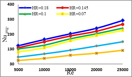
Figure 8. Variation of Nu with Re at several values of HR at θ = 60°, TT only, and plain tube
At first, the heat transfer inside the channel was looked at for all configurations, and the Nu was used to show how well heat was moving. Simulations were executed for Re between 5,000 and 25,000. Figures 6, 7, and 8 show that the Nu is going up, which is a good thing because it is related to the Re (flow velocity). The data also show that the 60° winglet orientation angle makes the Nu go up the greatest compared to the other angles that were evaluated. This is a clear and big difference. The Nu for the 60° instance went up by about 13% compared to the 45° example and by 21% compared to the 30° case.
Also, these numbers show how the triangular winglet obstructions affect things. A comparative analysis was performed between the TT alone and the TT in conjunction with obstacles across various winglet height ratios (HR = 0.18, 0.145, 0.1, and 0.07). The Nu increased as the winglet height increased, reaching its highest value of Nu = 344.21 at an HR of 0.18 and a Re of 25,000. This improvement is due to the larger recirculation zones that emerge behind taller obstacles. These zones make eddies and turbulence levels in the flow stronger, which speeds up heat transfer.
Figure 9. Variation of (Nuw/Nuo) with Re at several values of HR at θ = 30°, TT only and plain tube
Figure 10. Variation of (Nuw/Nuo) with Re at several values of HR at θ = 45°, TT only and plain tube
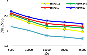
Figure 11. Variation of (Nuw/Nuo) with Re at several values of HR at θ = 60°, TT only and plain tube
The formation of a thermal boundary layer near the heated surface usually limits heat transfer. TT inserts greatly improve convective heat transmission by causing strong mixing between the core flow and the fluid next to the wall. This stronger contact makes turbulence stronger and the thermal boundary layer thinner. Adding winglet-shaped barriers makes this effect even stronger by creating secondary vortices, which make it easier for thermal energy to move between the fluid and the tube wall. Winglets also increase the effective heat transfer surface area, which improves the total convective performance. Better mixing in the flow also helps the temperature spread out more evenly across the duct.
The better heat transfer performance at the 60° winglet orientation angle can be explained by the fact that it blocks more flow. This greater barrier makes turbulence worse and makes vortices form more easily, which helps fluids mix and heat transfer happen more quickly. As the winglet angle gets bigger, the turbulence is stronger because the flow is redirected more, which creates stronger secondary vortices and more vortex shedding. All of these things work together to make convective heat transfer more efficient.
In Figures 9, 10 and 11, the value of the thermal reinforcement ratio (Nuw/Nuo) has a negative gradient with the Re rise. Therefore, the thermal reinforcement ratio (Nuw/Nuo) decreases with increasing Re. This is due to the fact that as the value of the Re (velocity of flow) growing up, the Nu also increases as the Nu increases in the addition of obstacles to the TT.
Also, of course, the case of a 60° angle gives the higher values of thermal reinforcement ratio. Where it gives (Nuw/Nuo) = 2.77 for HR = 2.77 at Re = 5000.
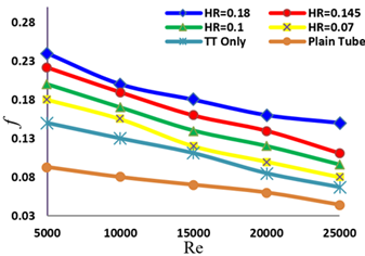
Figures 12, 13, and 14 show quite clearly that the coefficient of friction, which is a measure of pressure drop in this paper, went down a lot in all the tests. The higher friction factor values for the TT with 60° obstacles, compared to other TT setups and the plain tube, can be explained by the fact that the flow path is blocked by obstacles at larger angles, which makes a bigger recirculation zone behind the obstacles. According to the study [39], this, along with the action of the TT, makes the vortex stronger and the flow more turbulent. This causes a bigger pressure drop down the tube.
As a final result of studying the behavior of the fluid and the effect of the presence of TT and adding obstacles, on the overall performance of the heat transfer process inside the pipe. As is clear in the three Figures 15, 16, and 17, each of which displays a comparison according to the angles of orientation of the obstacles that are inserted with the TT. The 60-degree angle case showed the highest overall performance, η = 1.8 at Re = 5000. Followed by the case of angle of 45o η = 1.76 at Re = 5000, then angle of 30o gives η = 1.72 at Re = 5000. While the case of the tube with only the twist gave a lower overall performance, it had η = 1.53.
The stronger obstruction created by the sharper angle, which drastically changes the local flow field, is responsible for the better thermal performance shown with a 60° winglet angle. Larger recirculation zones are produced by this arrangement, which also causes early flow separation behind the obstructions and high-intensity longitudinal vortices. Greater turbulence levels and better heat blending throughout the duct are the results of the combined action. Higher local Nu and thin thermal boundary layers are also caused by the high angle's increased local velocity gradients close to the wall. When contrasted to the 45° and 30° designs, this provides noticeable improvements with regard to Nu and η values.
Figure 12. Variation of (f) with Re at several values of HR at θ = 30° and TT
Figure 13. Variation of (f) with Re at several values of HR at θ = 45° and TT
Figure 14. Variation of (f) with Re at several values of HR at θ = 60° and TT
Figure 15. Variation of η with Re at several of HR at θ = 30° and TT
Figure 16. Variation of η with Re at several of HR at θ = 45° and TT
Figure 17. Variation of η with Re at several of HR at θ = 60° and TT
(a) At axial direction equals 162 mm
(b) At axial direction equals 362 mm
(c) At axial direction equals 622 mm
Figure 18. Velocity contour (at Re = 5000) for TT without winglet
(a) At axial direction equals 162 mm
(b) At axial direction equals 362 mm
(c) At axial direction equals 622 mm
Figure 19. Velocity contour (at Re = 5000) for TT with winglet (60°)
Figure 20. Velocity vectors of TT without winglet at Re = 5000
Figure 21. Velocity vectors of TT with winglet at Re = 5000, HR = 0.07, θ = 60°
Figures 18 and 19 present detailed velocity contour diagrams for two configurations: a tube equipped with TT alone and a tube fitted with TT combined with triangular winglets at a winglet attack angle of 60°.
In general, the velocity contours show noticeable variations along the axial length of the tube, even under fixed inlet velocity conditions. These contours reveal the presence of strong swirling motion that persists over extended axial distances, indicating an increase in angular momentum, particularly at axial locations A = 162 mm, B = 362 mm, and C = 622 mm.
However, the strength and coherence of the swirling flow structures gradually diminish at these axial positions (frames A, B, and C), which is attributed to the dissipation of angular momentum. This decline in swirling intensity reflects the natural decay of induced vortices as the flow progresses downstream.
Figures 20 and 21 show velocity vector diagrams for two setups: (a) a tube with only TT, and (b) a tube with TT and triangular winglets at an attack angle of 60° and a winglet HR of 0.07. These setups are shown for the sake of comparison. The velocity vectors show that the flow speed slowly rises and approaches the wall of the tube. Also, the TT changes the flow geometry, which causes apparent abnormalities and instabilities in the flow field.
In case (b), adding triangular winglets makes the turbulence and flow disruption much worse than in case (a). The winglets make the swirling motion stronger and block the flow route, which makes the turbulence stronger and the mixing better, which helps the heat transmission.
Figure 22. Validation between the current study and Eiamsa-ard et al. [40]
To confirm the current numerical method, the findings of this investigation were juxtaposed with experimental data from Eiamsa-ard et al. [40], who examined a tube fitted with twin TTs of 9 mm in width and 1000 mm in length. Figure 22 illustrates a comparison of the Nu derived from the current simulation with that documented by Eiamsa-ard et al. [40], represented as a function of the Re. The results show that the current numerical model and the experimental data match well, with a maximum difference of about 10%.
The numerical model utilized in this study demonstrates a high level of accuracy, hence affirming the validity of the numerical approach. The numerical technique is valid since the numerical model used in this study is quite accurate.
The primary reason for the enhancement in heat transfer with increasing winglet angles is the intensification of turbulent flow. Increased turbulence reduces the thickness of the thermal boundary layer and enhances the convective heat transfer coefficient. Additionally, it promotes more effective energy exchange between the fluid and the tube walls. Therefore, incorporating winglet obstacles onto the TT at steeper angles significantly improves heat transfer performance. However, this improvement comes at the cost of increased pressure drop. Consequently, it is crucial to identify an optimal winglet angle that achieves a balance between maximizing heat transfer and minimizing energy losses associated with pressure drop.
This study numerically investigated the airflow characteristics and thermal performance inside a tube equipped with double TTs, both with and without triangular winglets. The key findings are summarized below:
1. The 60° angle of the obstacle showed the most increase in the Nu of all the configurations that were examined. In particular, it raised Nu by 13% compared to the 45° instance and by 21% compared to the 30° example.
2. The rise in HR (winglet height-to-diameter ratio) is mostly to blame for the increase in heat transfer that was seen. A taller obstruction makes the recirculation zones behind it bigger, which makes the eddy strength and turbulence intensity stronger. Both of these things make convective heat transfer better.
3. The 60° winglet angle likewise gave the highest thermal enhancement ratio, with (Nuₚ/Nu₀) = 2.77 for HR = 0.18 at Re = 5000.
4. The thermal enhancement ratio (Nuₚ/Nu₀) goes down as the Re goes up. This is because a larger flow velocity already raises the Nu, which makes the new barriers less important.
5. Numerical simulations clearly show that adding double-TTs with triangular winglets makes turbulent heat transfer much better. The setup with a 60° winglet angle and HR = 0.18 got a total performance factor of η = 1.8 at Re = 5000.
6. Adding winglets helps heat transfer, but it also makes the pressure drop bigger. So, it's important to choose the right wing shape and angle carefully to find a balance between thermal performance and energy efficiency, especially in systems where energy loss from pressure drop is a big problem.
7. There was an increase in heat transfer of up to 127%, but the friction factor was only slightly higher than in the simple tube or TT-only setups.
8. For HE that need to work really well, it is highly advised to utilize double TTs with triangular winglets at a 60° angle and HR = 0.18.
Furthermore, this configuration is suitable for compact or space-limited systems, such as electronics cooling or compact HVAC units, due to its favorable thermal performance even in the presence of elevated pressure drops.
The use of double TTs equipped with triangular winglets at a 60° orientation and HR = 0.18 is recommended for optimal thermal performance in turbulent flow conditions.
|
A |
Cross-section area, $\mathrm{m}^2$ |
|
$\mathrm{C}_{1 \varepsilon}, \mathrm{C}_{2 \varepsilon}$ |
Empirical constants in standard $\mathrm{k}-\varepsilon$ model |
|
D |
Hydraulic diameter, m |
|
f |
friction factor |
|
G |
Turbulent kinetic energy |
|
h |
Mean heat transfer coefficient, $\mathrm{w} / \mathrm{m}^2 . \mathrm{K}$ |
|
k |
Thermal conductivity, $\mathrm{W} / \mathrm{m} . \mathrm{K}$ |
|
L |
Length of tube, m |
|
$p$ |
pressure, Pascal |
|
Re |
Reynolds number |
|
U |
average velocity, $\mathrm{m} / \mathrm{sec}$ |
|
w |
Tape width, m |
|
y |
Tape pitch, m |
|
$\alpha$ |
Wing attack angle |
|
$\beta$ |
diameter ratio, $d / D$ |
|
$\delta$ |
Tape thickness, m |
|
$\Delta P$ |
pressure drop through the tube |
|
$\epsilon$ |
Turbulent energy dissipation rate |
|
$\mu$ |
Viscosity, $\mathrm{N} \cdot \mathrm{sec} / \mathrm{m}^2$ |
|
$\mu_t$ |
Turbulent viscosity |
|
$\rho$ |
density, $\mathrm{Kg} / \mathrm{m}^3$ |
[1] Erfanian Nakhchi, M., Rahmati, M.T. (2020). Turbulent flows inside pipes equipped with novel perforated V-shaped rectangular winglet turbulators: Numerical simulations. Journal of Energy Resources Technology, 142(11): 112106. https://doi.org/10.1115/1.4047319
[2] Rahman, M.A., Hasnain, S.M., Paramasivam, P., Zairov, R., Ayanie, A.G. (2025). Solar drying for domestic and industrial applications: A comprehensive review of innovations and efficiency enhancements. Global Challenges, 9(2): 2400301. https://doi.org/10.1002/gch2.202400301
[3] Li, X., Li, Z.H., Zhai, Y.L., Wang, H. (2025). Numerical study on the enhancement of local and average heat transfer in supercritical CO2 horizontal flow by twisted tape inserts. International Communications in Heat and Mass Transfer, 163: 108699. https://doi.org/10.1016/j.icheatmasstransfer.2025.108699
[4] Rahman, M.A., Sarikonda, P., Chatterjee, R., Hasnain, S.M. (2025). Enhancing solar energy conversion in current PV and PVT technologies through the use of metasurface beam splitters: A brief review. Plasmonics, 1-22. https://doi.org/10.1007/s11468-025-02774-2
[5] Nashee, S.R., Mushatet, K.S. (2025). Impact of ribs with multiple arrangements on the behavior of a turbulent flow in a rectangular channel. Journal of Heat and Mass Transfer Research, 12(2): 259-270. https://doi.org/10.22075/jhmtr.2025.34713.1575
[6] Rishack, Q.A., Mushatet, K.S., Ouda, A.A. (2018). Numerical investigation of non-newtonian fluids flow in two direction double step square expansion. In 2018 International Conference on Advance of Sustainable Engineering and its Application (ICASEA), Wasit-Kut, Iraq, pp. 210-214. https://doi.org/10.1109/ICASEA.2018.8370983
[7] Nashee, S.R. (2023). Numerical study for fluid flow and heat transfer characteristics in a corrugating channel. International Journal of Heat & Technology, 41(2): 392-398. https://doi.org/10.18280/ijht.410213
[8] Al Qudah, S., Radwan, A., El-Sharkawy, I.I. (2025). Experimental analysis of heat transfer in a circular tube fitted with new twisted tape insert with rings using response surface methodology. International Journal of Heat and Fluid Flow, 112: 109713. https://doi.org/10.1016/j.ijheatfluidflow.2024.109713
[9] Lin, Z.M., Wang, L.B., Lin, M., Dang, W., Zhang, Y.H. (2017). Numerical study of the laminar flow and heat transfer characteristics in a tube inserting a twisted tape having parallelogram winglet vortex generators. Applied Thermal Engineering, 115: 644-658. https://doi.org/10.1016/j.applthermaleng.2016.12.142
[10] Shakir, R. (2022). Study of pressure drop and heat transfer characteristics of mini-channel heat sinks. The Iraqi Journal for Mechanical and Materials Engineering, 22(2): 85-97. https://doi.org/10.32852/iqjfmme.v22i2.595
[11] Nashee, S.R. (2024). Enhancement of heat transfer in nanofluid flow through elbows with varied cross-sections: A computational study. International Journal of Heat and Technology, 42(1): 311-319. https://doi.org/10.18280/ijht.420133
[12] Selvam, S., Thiyagarajan, P.R., Suresh, S. (2014). Experimental studies on effect of bonding the twisted tape with pins to the inner surface of the circular tube. Thermal Science, 18(4): 1273-1283. https://doi.org/10.2298/TSCI120807036S
[13] Chang, S.W., Yang, T.L., Liou, J.S. (2007). Heat transfer and pressure drop in tube with broken twisted tape insert. Experimental Thermal and Fluid Science, 32(2): 489-501. https://doi.org/10.1016/j.expthermflusci.2007.06.002
[14] Noothong, W., Suwannapan, S., Thianpong, C., Promvonge, P. (2015). Enhanced heat transfer in a heat exchanger square-duct with discrete V-finned tape inserts. Chinese Journal of Chemical Engineering, 23(3): 490-498. https://doi.org/10.1016/j.cjche.2014.05.018
[15] Eiamsa-ard, S., Thianpong, C., Eiamsa-ard, P., Promvonge, P. (2009). Convective heat transfer in a circular tube with short-length twisted tape insert. International Communications in Heat and Mass Transfer, 36(4): 365-371. https://doi.org/10.1016/j.icheatmasstransfer.2009.01.006
[16] Tamna, S., Kaewkohkiat, Y., Skullong, S., Promvonge, P. (2016). Heat transfer enhancement in tubular heat exchanger with double V-ribbed twisted-tapes. Case studies in thermal engineering, 7: 14-24. https://doi.org/10.1016/j.csite.2016.01.002
[17] Krishna, S.R., Pathipaka, G., Sivashanmugam, P. (2009). Heat transfer and pressure drop studies in a circular tube fitted with straight full twist. Experimental Thermal and Fluid Science, 33(3): 431-438. https://doi.org/10.1016/j.expthermflusci.2008.10.007
[18] Wongcharee, K., Eiamsa-ard, S. (2011). Enhancement of heat transfer using CuO/water nanofluid and twisted tape with alternate axis. International Communications in Heat and Mass Transfer, 38(6): 742-748. https://doi.org/10.1016/j.icheatmasstransfer.2011.03.011
[19] Murugesan, P., Mayilsamy, K., Suresh, S., Srinivasan, P.S.S. (2011). Heat transfer and pressure drop characteristics in a circular tube fitted with and without V-cut twisted tape insert. International Communications in Heat and Mass Transfer, 38(3): 329-334. https://doi.org/10.1016/j.icheatmasstransfer.2010.11.010
[20] Murugesan, P., Mayilsamy, K., Suresh, S. (2012). Heat transfer in a tube fitted with vertical and horizontal wing-cut twisted tapes. Experimental Heat Transfer, 25(1): 30-47. https://doi.org/10.1080/08916152.2011.559567
[21] Hasan Ibrahim, S., Abdul Wahhab, H.A. (2022). Influence of twisted tape inserts with perforation on heat transfer and pressure drop inside circular tube: Numerical and experimental investigation. In ICPER 2020: Proceedings of the 7th International Conference on Production, Energy and Reliability. Springer, Singapore, pp. 281-293. https://doi.org/10.1007/978-981-19-1939-8_24
[22] Chokphoemphun, S., Pimsarn, M., Thianpong, C., Promvonge, P. (2015). Thermal performance of tubular heat exchanger with multiple twisted-tape inserts. Chinese Journal of Chemical Engineering, 23(5): 755-762. https://doi.org/10.1016/j.cjche.2015.01.003
[23] Saha, S.K., Dutta, A. (2001). Thermohydraulic study of laminar swirl flow through a circular tube fitted with twisted tapes. Journal of Heat Transfer, 123(3): 417-427. https://doi.org/10.1115/1.1370500
[24] Saha, S.K., Dutta, A., Dhal, S.K. (2001). Friction and heat transfer characteristics of laminar swirl flow through a circular tube fitted with regularly spaced twisted-tape elements. International Journal of Heat and Mass Transfer, 44(22): 4211-4223. https://doi.org/10.1016/S0017-9310(01)00077-1
[25] Suri, A.R.S., Kumar, A., Maithani, R. (2017). Heat transfer enhancement of heat exchanger tube with multiple square perforated twisted tape inserts: Experimental investigation and correlation development. Chemical Engineering and Processing: Process Intensification, 116: 76-96. https://doi.org/10.1016/j.cep.2017.02.014
[26] Bhuiya, M.M.K., Chowdhury, M.S.U., Ahamed, J.U., Khan, M.J.H., et al. (2012). Heat transfer performance for turbulent flow through a tube using double helical tape inserts. International Communications in Heat and Mass Transfer, 39(6): 818-825. https://doi.org/10.1016/j.icheatmasstransfer.2012.04.006
[27] Nashee, S., Mushatet, K.S. (2024). Performance study on turbulent heat transfer using rectangular air duct integrated with continuous and intermittent ribs turbulators. Thermal Science, 29(2): 955-967. https://doi.org/10.2298/tsci240430214n
[28] Rahman, M.A. (2024). Thermo-fluid performance of axially perforated multiple rectangular flow deflector-type baffle plate in an tubular heat exchanger. Applications in Engineering Science, 20: 100197. https://doi.org/10.1016/j.apples.2024.100197
[29] Piriyarungrod, N., Eiamsa-Ard, S., Thianpong, C., Pimsarn, M., Nanan, K.J.C.E. (2015). Heat transfer enhancement by tapered twisted tape inserts. Chemical Engineering and Processing: Process Intensification, 96: 62-71. https://doi.org/10.1016/j.cep.2015.08.002
[30] Sattar, E.A., Ouda, A.A., Salman, M.D. (2023). Enhancement heat transfer in shell and tube heat exchanger by used hybrid and nanofluid. AIP Conference Proceedings, 2787: 030006. https://doi.org/10.1063/5.0160929
[31] Nashee, S.R. (2024). Numerical simulation of heat transfer enhancement of a heat exchanger tube fitted with single and double-cut twisted tapes. International Journal of Heat & Technology, 42(3): 1003-1010. https://doi.org/10.18280/ijht.420327
[32] Shakir, R. (2023). Prediction study of the boiling flow of heat transfer in an array of in-line micro-pin-fins heat sink. AIP Conference Proceedings, 2845: 060003. https://doi.org/10.1063/5.0157017
[33] Özdemir, S., Kılıç, M., Çalışır, T. Başkaya, S. (2023). Numerical investigation of enhancing mixed convection heat transfer by using semi-cylindrical obstacles in a vertical channel. Journal of the Faculty of Engineering and Architecture of Gazi University 38(3): 1805-1820. https://doi.org/10.17341/gazimmfd.1008154
[34] Nashee, S.R., Ibrahim, Z.A., Kamil, D.J. (2024). Numerical investigation of flow in vertical rectangular channels equipped with three different obstacles shape. AIP Conference Proceedings, 3122: 100002. https://doi.org/10.1063/5.0216016
[35] Sattar, E.A., Ouda, A.A., Salman, M.D. (2022). Improvement of thermal performance for shell and tube heat exchanger with different baffles. International Journal of Mechanical Engineering, 7(1): 1260-1269. https://www.researchgate.net/publication/365186983
[36] Hamood, H.M., Mansour, M.M., Lafta, A.M., Nashee, S.R. (2023). Numerical investigation to study the effect of three height of triangular obstacles on heat transfer of nanofluids in a microchannel. International Review of Mechanical Engineering (IREME), 17(11): 533-540. https://doi.org/10.15866/ireme.v17i11.23627
[37] Rahman, A. (2023). Experimental investigations on single-phase heat transfer enhancement in an air-to-water heat exchanger with rectangular perforated flow deflector baffle plate. International Journal of Thermodynamics, 26(4): 31-39. https://doi.org/10.5541/ijot.1285385
[38] Mansour, M.M., Hamood, H.M., Lafta, A.M., Nashee, S.R., Shkarah, A.J. (2024). Enhancing the efficacy of adsorption-based carbon storage systems: A finite element analysis approach. International Journal of Energy Production and Management, 9(1): 19-24. https://doi.org/10.18280/ijepm.090103
[39] Al-Karboly, A.M.O., Ibrahim, A., Fazlizan, A., Sopian, K., et al. (2025). Experimental evaluation of a photovoltaic thermal collector using twisted tape absorber with nano-enhanced phase change material for thermal storage. Journal of Energy Storage, 109: 115122. https://doi.org/10.1016/j.est.2024.115122
[40] Eiamsa-ard, S., Thianpong, C., Eiamsa-ard, P. (2010). Turbulent heat transfer enhancement by counter/co-swirling flow in a tube fitted with twin twisted tapes. Experimental Thermal and Fluid Science, 34(1): 53-62. https://doi.org/10.1016/j.expthermflusci.2009.09.002