Wafeeqa Abdulrazak Hasan![]()
© 2025 The author. This article is published by IIETA and is licensed under the CC BY 4.0 license (http://creativecommons.org/licenses/by/4.0/).
OPEN ACCESS
This paper proposes a Hybrid AC/DC Microgrid (HMG) system comprising a wind energy control system (WECS), a photovoltaic (PV) system, and a battery system. Because microgrids emit fewer carbon gases and may be connected to the utility grid, researchers are finding them more and more appealing. The HMG increases system efficiency and power quality by reducing multiple reverse conversions. The VSC system functions as a DC/AC bus control system and employs used bacteria foraging optimization (BFO) algorithm to adjust the proportional integral (PI) controller settings to reduce AC and DC switching. Furthermore, for the battery energy storage system (BESS) and wind turbine speed regulation utilize two PI controllers. Lastly, the maximum power point (MPP) of the PV system was investigated using perturbation and observation (P&O), incremental conductance (IC), fuzzy logic controller (FLC), and maximum power point tracking (MPPT). The FLC technique showed the benefit of attaining the finest outcomes, specifically power (99.68 kW) and efficiency (99.84%). The results show that the suggested approach works well for accomplishing the primary goals of the hybrid microgrid. The simulations in this study were carried out using MATLAB/Simulink.
photovoltaic (PV), fuzzy logic controller (FLC), maximum power point tracking (MPPT), wind energy control system (WECS), battery energy storage system (BESS), hybrid system, AC/DC microgrid
For many years, small autonomous grids have been in place in isolated villages where connecting to the main power grid is impractical for technical or financial reasons. Fossil-fuel production methods have been the most popular option for supplying electricity in these remote grids because of their scalability, affordable investment costs, and adaptable operation. However, integrating greener generation technologies based on solar, wind, hydrogen, and hydro power has become a priority in microgrids due to their proven technical and financial viability [1]. Currently, the electrical industry is dealing with two main issues: (a) increasing the number of people who are not currently served by the grid and (b) satisfying the growing demand from those who are served by the grid. Globally, 20% of electricity generated in the next ten years (by 2020) must come from renewable energy sources [2]. The concept of renewable energy systems (RES) presents a more sustainable technology that can meet the increasing electrical needs of remote and networked populations. Microgrids (MGs) have recently piqued the curiosity of scientists as a possible future alternative to traditional energy sources. With MGs' assistance, it is believed to be feasible to integrate various sources of RES within conventional grid [1].
Despite unexpected events and crowded distribution grids, MGs offer great dependability in their ability to function, in addition to cleanly and dependably integrating distributed energy throughout the main grid. This lowers the loss of electricity throughout the transport and distribution processes and shortens the period needed for investing and implementation [3]. The studies [4, 5] were reviewed, and some of them were put into practice. Several instances are found in various nations across the globe. The bulk of MGs are located in Europe, as are the United States and Japan.
A low-voltage distribution power system MG is characterized by the connection of small modular generation systems, which include distributed generators (DGs), sustainable sources of energy, and additionally intermediate storage containers, to meet load demands. The utility grid has the ability to handle this specific power system as either a generator or a controlled load [6]. According to the type of source that provides the control, Microgrids fall into one of three categories: hybrid, alternating current (AC), or direct current (DC) [7]. Microgrids are the best option for delivering electricity to isolated regions of a nation where the output of the national grid network is constrained by design, rendered inoperable by bad weather, or interrupted by human activity [8].
As a result, the microgrid's economic operation is its primary concern. Numerous scholars are investigating ways to maximize microgrid operation activities [9]. Some studies are particularly focused on AC MG because of its compatibility with the main grid, even though MG systems can be entirely DC, AC, or a hybrid of the two technologies [3, 10, 11].
A better design approach for FLC systems for a DC microgrid under variable atmospheric conditions is suggested by this study. It will enhance the reaction stability and dependability of the system. An FLC uses DC-DC boost converters to assess PV and FC in order to achieve this improved accuracy and response time [12]. The bacteria foraging optimization (BFO) algorithm was used in the article to optimize an isolated microgrid model that incorporates both a traditional diesel-fueled generating unit and renewable energy sources like solar and wind. Two-Swim Modified BFOA (TS-MBFOA) and Normalized TS-MBFOA (NTS-MBFOA) are two new iterations of the BFOA that were put into practice and evaluated. The results demonstrated that TS-MBFOA outperformed NTS-MBFOA and the evolutionary algorithm LSHADE-CV in terms of numerical solutions. But from a mechatronic perspective, the optimal solution identified by NTS-MBFOA is superior since it extends the IMG's lifespan, which eventually leads to financial savings [13].
In recognition of the nature of most renewable energy methods, MG designs incorporate power electronics. The injected power supplied to the MG must be managed [11]. Its power quality issues might be resolved if suitable closed-loop control methods are used [14]. Parallel inverter utilization has the potential to enhance the performance of many technologies and MG arrangements [15]. The main energy resource in a typical hybrid energy system is typically less available than the secondary resource, which is typically more available. For the situation, especially during the winter months, when solar radiation is at its lowest, wind speed is typically very high. While wind energy has been effectively used, sunlight can to be used to generate power throughout the night. In addition to this, meeting consumer load requirements through the simultaneous use of diverse energy resources is greatly improved [16].
The purpose of this research is to improve the power quality of a proposed hybrid MG system and to reduce AC and DC switching to improve efficiency, and enhance the quality of the power it produces, which consists of PV, wind and battery with a control system for each unit. As a result, a fuzzy logic-based controller for PV systems is designed. The controller connects the battery through BBDC and a permanent magnet synchronous generator (PMSG) wind power system, and synchronizes its output with the power grid to improve the power quality. The VSC controller is coordinated with the PWM of the inverter installed on the power supply system with the power grid.
Distributing the paper in this manner: Part 2 describes the general structure of a microgrid. Each element of the proposed hybrid microgrid system is explained in Section 3. Proposed model and then modeling photovoltaic (PV) in subsystem (3.1) and subsystem for battery storage of electricity (3.2) are covered in detail in their respective subsections. Modeling the PMSG wind turbine in subsystem (3.3). The voltage source converters (VSC) within the AC/DC bus subsystem are fully described in section 3.4. In Section 4, the controlling techniques applied to the system's hybrid microgrid sources were explained. Section 5 displays the simulated findings within MATLAB/Simulink software. The results of the three technique scenarios have been tallied and compared. Lastly, but not least, Section 6 contains the conclusions.
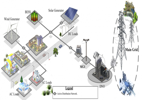
Figure 1 shows a number of components and subsystems of systems, such as battery storage, distributed generation, and a variety of loads. The assembled MGs operate in three modes: linked mode, where they adopt the main grid set points; isolated mode, where they have their own power sources; and parallel mode, which operates without exchanging power with the Main Grid [3]. However, the following types of types might also be taken into consideration when classifying MGs: Voltage comes in three kinds: DC, AC, and hybrid. There are three neutral distribution topologies on offer: single-phase, three-phase, and three-phase. There are two voltages offered: low voltage (LV) and medium voltage (MV). Rings, along with radial structures, are the two forms [17].
Figure 1. Electrical hybrid micro grid
The principle for AC/DC Hybrid MGs came from when the two configurations are combined, offering a better strategy that includes the most important advantages for both DC and AC MGs [3]. However, there are three established designs for isolated AC: a three-stage partly separate design, a two-stage entirely separate arrangement, and a two-stage partly separated design. The application, along with the environment in which the AC/DC HMG is integrated, has a significant impact on the configuration that needs to be defined [5, 18]. An AC transformer connects the AC MG to the major grid electrically, anchoring it within the electrical grid. This is the most important aspect of the connected design that sets it apart from other arrangements [19]. A few requirements that must be satisfied when constructing an AC/DC HMG include economy, flexibility, accessibility, controllability, along dependability [18].
This section provides an explanation of the suggested design. In the MATLAB/Simulink environment, the system was implemented with the appropriate Simscape program. The purpose is to present researchers with an instrument and a deeper comprehension of the MG behavior and all of its constituent parts, as well as the control techniques that are used for this proposed HMG system, in addition to their general effects for enhancing power quality in various operational prerequisites.
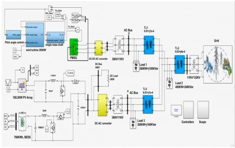
Figure 2 shows a depiction of the proposed hybrid MG. The schematic below shows how the MG is connected to an electricity sub-transmission scheme to the main grid. This MG is made up of a battery, PV array, and a conversion of wind energy at a changing speed based on the PMSG. The maximum power point tracking (MPPT) algorithm controls PV sources of energy that are connected to a DC bus. Whereas in the WT situation, we will utilize a proportional integral (PI) controller to act on the pitch angle control in order to maximize power extraction amounts and control the quantity of power produced at its rate value. The battery served as a storage device, and it connected to the DC bus through a bidirectional DC/DC Buck Boost converter. Weather-related factors affect wind and solar power systems, and solar electricity is nonexistent at night. As a result, a battery by itself is unable to meet the load demand in conditions of prolonged no wind or low sun. Weather-related factors affect wind and solar power systems, and solar electricity is nonexistent at night. And a battery by itself is unable to meet the load demand in conditions of prolonged no wind or low sun. Furthermore, the VSC acts as a control system on DC/AC buses, utilizing feedback signals for voltage and current. Droop controllers can then produce reference signals, allowing for the intelligent application of another device to regulate the microgrid's voltage and frequency. The bacteria-foraging optimization approach is used to modify the controller's parameters (Kp, Ki). For both real and DC its elements, this PI-BFO system controller acts like a current regulator. In the suggested hybrid power generation system, VSC will safeguard the renewable energy sources.
Figure 2. Proposed hybrid MG system
3.1 Solar-photo voltaic system (PV)
PV modules' voltage-current along with voltage-power relationships is evident that the PV panel's maximum power is achieved in proximity to its open circuit voltage [20-22]. In Eq. (1), the PV model's voltage-current (V-I) characteristics are provided by the study [23]:
$I_{p v}=I_{p h}-I_s e^{\left(\frac{q\left(V_{p v}+R_s I_{p v}\right)}{n k T}-1\right)}-\frac{V_{p v}+R_s I_{p v}}{R_{s h}}$ (1)
where, Iph is the photo-current, Is is the diode saturation current, q is the electron charge, T is the temperature in (K), n is the P-N junction ideality factor, and Rs and Rsh are the intrinsic series and shunt resistances of the PV cell, respectively.
The most significant of the distributed sustainable energy supplies utilized in MG is solar-PV technology, which uses the MATLAB/Simulink software to model the PV cells' performance. At a temperature of 25℃, an overall value of G=1000 W/m2 is applied to the dual arrays during operation across the cells that produce electricity. The data from each module in this PV is used to produce a standard power output of 213.15 kW for the DC Bus.
3.2 Wind energy control system (WECS)
All wind system needs wind turbines. They work as the main movers of generators that produce electricity and are attached to their shafts. Axis wind turbines can be broadly classified as either vertical axis wind turbines (VAWT) or horizontal axis wind turbines (HAWT), based on the direction in which the turbines rotate. Depending on how they operate, they are further classified into constant speed and varying speed varieties. The wind energy conversion system's wind generator models and wind turbine parameters are the main factors affecting the WECS's mode of performance [24].
3.2.1 Features of a wind turbine
The following represents the aerodynamic power factor, or Cp, for the wind turbine, which is a measure utilized for expressing the turbine's electrical power generation as in Eq. (2):
$P=0.5 \rho_a A C_P V^3$ (2)
where, A describes the swept area in m2, V represents the wind velocity speed in m/sec, and ρ represents the air density in kg/m3. Eq. (2) shows how wind power is affected by air density, rotor area, and wind speed [24].
As follows: One measure of a wind turbine's performance is its aerodynamic power factor, which is established using the blade pitch angle (β) and tip-speed ratio (λ). A general Cp equation is determined by the properties of the turbine [23]. With varying values of β, the Cp varies with λ as explained by Eq. (2). Maintaining λ at the optimal level for all wind speeds is necessary for operating the WECS with the highest Cp value [25, 26]. This is just possible with operation at variable speeds using DFIG or PMSG, which allows the turbine's speed of rotation to be changed according to changes in wind speed [27]. In large wind systems, in order to set the electrical energy produced by the wind turbines within a predetermined limit, pitch angle control is usually utilized, pitch angle control is usually utilized, particularly during high speeds of wind [27].
3.2.2 PMSG
Typically, a PMSG in a wind energy conversion system is constructed with multiple poles. It therefore operates slowly in synchronization with the wind turbine's rotational speed. Hence, PMSG and the rotor shaft of the wind turbine are intimately related.
One such activity that doesn't need additional gearbox arrangements is the direct-drive operations [28]. According to their greater efficiency, these generator types are favored in designs that are small. Permanent magnetic materials are expensive, which has constrained their application, even though large-scale designs have been explored. The system for electricity from wind conversion with PMSG that employs a standard AC-DC-AC transformation process [29, 30]. Through the utilization of electrical power conversion devices, the stator can be linked to the electrical grid. A standard wind energy transformation system utilizing PMSG. Because without a spare rotor management is present, the electrical power converters in utilize operate at their full capacity, increasing the efficiency of energy from wind conversion throughout a wide range of wind speeds. Additionally, full capacity power converters don't need extra equipment to be used in fault ride-through situations and help to comply with various grid rules [28].
3.3 Battery energy storage system (BESS)
The irregular variable behavior of distributed energy from renewable sources causes it to be extremely difficult to manage and operate the micro grid. The PV system thus requires an energy storage system (ESS). In order to maintain frequency as well as voltage at the scheduled levels, the ESS adjusts the power output. This allows it to provide the islanded micro grid with the appropriately defined voltage and frequency supports [29].
The BBES unit in this HMG system is connected over a DC bus, which has a voltage higher than the battery connected across it. Consequently, the battery and a buck-boost converter are linked, which adjusts the electrical voltage of the battery based on the operational parameters of the PV system, for the purpose of managing its energy use.
3.4 A DC-DC buck boost bidirectional converter (BBDC)
The solar system and batteries are integrated into a bidirectional converter that converts DC to DC. Through the use of a bidirectional DC-DC converter, electricity can flow both ways—from a load into a BESS. Assuming there is enough available irradiance to generate the essential voltage for running the load, power moves from the PV system towards the BESS, simultaneously charging the BESS [30]. Currently, the bidirectional converter will work in the buck state. The power is transferred from the BESS towards the load, and the BESS discharges as a result whenever the voltage required for the load can to be produced with the available irradiance. Bidirectional DC-DC converters are now operating in boost state. Bidirectional converter specifications are constructed with the assistance of Eqs. (3)-(5) [24]. Table 1 displays more information about this proposed hybrid microgrid.
Table 1. The microgrid system's parameters and specifications
|
Microgrid Systems |
Parameters |
Specifications |
|
Load Sizing |
DC Bus Voltage |
540 Vdc |
|
Requires Load Power |
2 kW |
|
|
AC Bus Voltage |
11 kV |
|
|
Load 1 Power Required |
200 kW+ j100 kVAR |
|
|
Load 2 Power Required |
400 kW+ j240 kVAR |
|
|
Load 3 Power Required |
200 kW+ j100kVAR |
|
|
PV Array Sizing |
PV module |
Soltech 1STH-215-P |
|
Max power per module |
213.15 W |
|
|
Max current |
7.35 A |
|
|
Max voltage |
29 V |
|
|
Parallel Strings |
47 |
|
|
Series Modules per string |
10 |
|
|
PMSG |
Rated Power |
200 kW |
|
Rated Speed |
360 R.P.M |
|
|
Battery Sizing |
Battery current capacity |
2000 Ah |
|
Battery Voltage |
280 Vdc |
|
|
Batteries capacity |
768 kWh |
$C_H=\frac{D}{R_H f_s\left(\Delta V_H / V_H\right)}$ (3)
$L_{b, \min } \geq \frac{D(1-D)^2 R_H}{2 f_s}$ (4)
As for the operation's buck:
$L_{b, \min } \geq \frac{D(1-D) R_L}{2 f_s}$ (5)
where, the load resistance at the boost and buck sides is denoted by RH and RL, respectively. CH is the boost side capacitance value. The switching frequency is fs, and the inductance's minimum value is Lb,min [24].
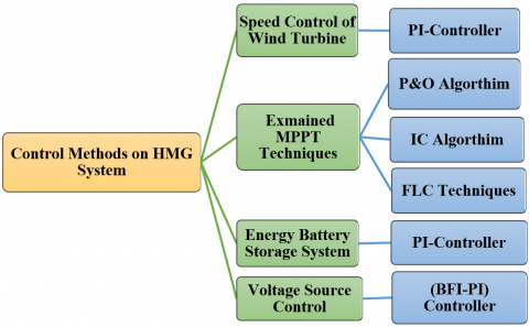
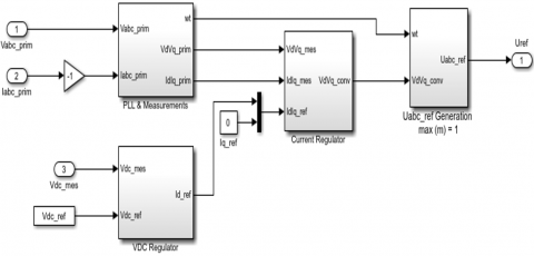
This hybrid microgrid's control system is organized split into four subsystems as can be seen from the Figure 3: battery unit controllers by use PI controller to manage the storage of battery system, control mechanism employed by voltage source controllers by used the BFO technique is employed to adjust the PI controller's specifications, which regulates the real and reference dc-link voltage when the boost converter's DC/bus output needs to be kept constant at a specific level. Furthermore, apply the same method to the AC-grid network in order to maintain the necessary voltage across the line. In WECS was adjust the pitch angle control by PI controller is used on wind turbine to eliminate problems caused by changes in wind speed WECS controllers, and MPPT for PV system control are examined the three methods as MPPT at same Circumstances, that the traditional methods were used P&O and IC algorithms, and FLC method, as shown in Figure 3 describe the controller design's experimental flowchart for the power units in proposed hybrid microgrid.
Figure 3. The controller design's experimental flowchart
Then the method that gave the best results was used for a boost converter. The control method's basic objectives are to improve power quality and safeguard the battery from charging excessively or excessive discharge, which may damage it and reduce its useful life. The controller maintains the batteries' state of charge within safe bounds as a result. All controllers' subsystem is covered thoroughly in the subsequent subsections.
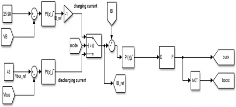
4.1 A DC-DC BBDC with battery system
The charging and discharging control circuit is designed based on the flowchart in the study [31]. Figure 4 shows the battery operating mode control circuit. The battery's current consumption during the first five seconds, the battery voltage at 50% of its state of charge, the reference voltage, and the battery's charging rate to achieve an 80% charge. Based on this data, we can incorporate a slow algorithm to continue charging the battery after 80% to maintain its life, as well as after the first five seconds. The battery will be charged to 80% of its capacity, depending on its current state. This indicates that a battery is in a drained state when the PV energy irradiation is less than 100 W/m2, and in a charging state when it is equal to or more than 100 W/m2. Because of this, the Battery Storage of energy System makes use of a PI controller circuit to determine the maximum value of the current and voltage in the state of the battery when it is charging, along with discharging, in order to identify their appropriate values for the two states of the battery. To extend and protect the battery's life, take note that its state of charge is at 50%. Additionally, the controller protects the battery from normal, overcharged, and over-discharged circumstances.
Figure 4. Charging and discharging the controller of battery
4.2 The voltage source converters (VSC) within the AC/DC bus
The variable output of the boost converter must be kept at a certain level (which is equal to or higher than the maximum AC supply of the main electrical network). Therefore, the controller of the PI regulates the reference along with the real DC-link voltages. The bacteria-foraging optimization method is employed to adjust the controller’s magnitudes (Kp, Ki). Its complete algorithm is described by the author in the study [32] and refers to this controller as PI-BFO.
Considering its line-to-line electrical voltage of the AC network is equivalent to 380 V, the voltage at the DC link is maintained at 380 × √2 ≈ 540 V. Additionally, the inverter's power factor is kept fixed at unity. For real current components along with direct reference, current regulating is provided by a further brilliant PI-BFO control system.
4.2.1 PI-BFO
An efficient global optimization method for resolving distributed optimization issues is the bacterial foraging optimization algorithm. BFO is derived from Escherichia coli's social foraging behavior. It has been found that BFO is highly effective in solving practical optimization issues across a range of engineering fields. The optimization technique adheres to the basic biological principle found in E. Coli's foraging behavior [33]. Natural selection favors animals with efficient foraging techniques and eliminates animals with ineffective ones, which is the fundamental idea behind BFO. Ineffective foraging strategies are removed after a certain number of rounds. Four mechanisms control the BFO's foraging strategy: chemotaxis, swarming, reproduction, and elimination and dispersal [34, 35].
The BFO algorithm can produce good results by employing unique algorithmic strategies that strike a balance between investigating novel possibilities and taking advantage of preexisting answers. This increases the rate at which the best solutions may be found, which makes it perfect for small-scale problems.
In Figure 5, the MATLAB/Simulink blocks and the overall control method are displayed. The output electrical voltage frequency variation equals 50 Hz, while the PWM frequency is 2 kHz. This figure depicts the suggested VSC system that is being investigated, the PLL, and the Measurements module. A Vdc reference set to 540 volts serves as the first input, while the magnitude of the electrical voltage within the DC bus serves as the second. The regulation process will produce undesired grid feedback to the renewable source of MG if the magnitude of the DC voltage comparison with the reference voltage is less than 540 volts. Thus, when Vdc equals or exceeds V reference, the inverter will activate. The inverter will operate if the other requirement is met, which is that the current must be zero or positive. Consequently, the inverter cannot function when the current value is negative in order to avoid main grid feedback on the PV and wind systems. Consequently, the method for regulating the current in the HMG system is to safeguard the renewable resources.
Figure 5. Three-arm inverter control methods for the DC-link voltage and current regulator
4.3 WECS
The PMSG is attached to a three-phase rectification with a bridge so as to transform an AC varying voltage to a fixed DC voltage. Subsequently, the DC bus voltage is raised and regulated at 500 V utilizing a voltage booster conversion. The necessary duty cycle is produced by a basic PI controller in order to give the booster converter the proper gated signals.
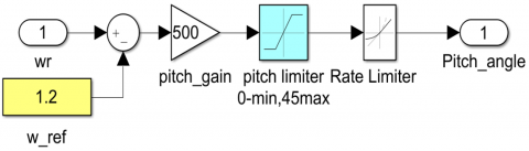
4.4 Control mode for pitch angle
A wind speed of 3 to 25 m/s is usually adequate for systems of wind turbines to function, and a wind speed of 12 to 16 m/s is sufficient for obtaining the rated power. The pitch angle regulator that controls the rotating speed is depicted in the study [36]. If the output of the generator is more than its rated power or if its rotating speed is lower than its maximum speed, in an attempt to enhance power, the pitch angle has been adjusted to zero. The wind turbine's pitch angle can be adjusted to restrict the rotating speed. If more power is generated than is rated, pitch angle adjustment is employed to limit the power to achieve the highest rated value. The controller, which is described by the PI controller, modifies the pitch angle by comparing ωm with the reference pitch angle (βref) [36].
In addition to an ESS, Figure 6 illustrates the use of a pitch angle controller for wind turbines to regulate speed in high-speed conditions.
Figure 6. Pitch angle control
4.5 MPPT controller for PV system
The maximum electricity point tracking algorithm is necessary to ensure that sources of sustainable energy provide the greatest amount of electricity in a variety of weather situations. The solar PV system produces power in proportion to the amount of sunshine that reaches its modules. Solar PV modules cannot produce the maximum amount of electricity due to the nonlinear properties of sunshine irradiation, which results in irregular availability [37].
Under a variety of conditions, to maintain the PV system functioning close to the PV panel's maximum power point (MPP), PV inverters employ the MPPT algorithm to continuously adjust the impedance that the solar array senses. like adjusting the load, temperature, and solar irradiation. MPPT algorithms are used by engineers designing solar inverters to optimize the power produced by PV systems. In accordance with the power voltage curve [20, 21].
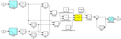
4.5.1 Perturbation and observation (P&O) algorithm as MPPT
For solar PV panels, a particularly popular algorithm for MPPT is the P&O algorithm because of its high efficiency of conversion and ease of application [36]. While this MPPT technique takes longer, it is less sensitive to large oscillations in terms of produced energy, along with other factors like the PV's output electrical voltage, than other MPPT algorithms, such as the incremental conductance (IC), to arrive at a stable state. This algorithm can be considered a hill-climbing algorithm because, up until the MPP is reached, generated power expands as voltage increases. Once MPP is attained, generated power drops as voltage increases [22]. To provide the highest level of power, this algorithm adjusts the operational voltage. Although this method has a number of advanced along with improved variations [21].
Therefore, a PV system controller is implemented in the proposed hybrid grid to verify the MPPT using the P&O algorithm, as shown in Figure 7 and compare the results with other proposed methods with this model.
Figure 7. Modeling of the MPPT controller based on the P&O algorithm
4.5.2 Incremental conductance (IC) algorithm as MPPT
For solar PV MPPT, the IC approach is a commonly used method. It relies on the notion that at MPP, the electrical power derivative of a PV panel with regard to electrical voltage equals zero. The value is positive toward the left of MPP and negative towards the right of MPP according to the P versus V graph [37]. This algorithm, which is displayed below, evaluates a PV system's IC against its instantaneous conductance. For the purpose of reaching the MPP, the amount of voltage. is either increased or decreased based on the result. When MPP is attained, the voltage doesn't change, in contrast to the P&O algorithm [21].
So, a PV system controller is implemented in the proposed hybrid grid to verify the MPPT using the IC algorithm, as shown in Figure 8, and compare the results with other proposed methods with this model.
Figure 8. MPPT controller modeling using the IC algorithm
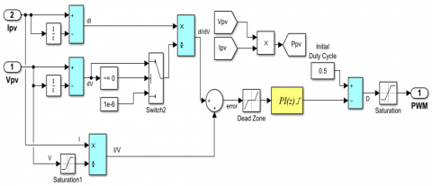
4.5.3 Fuzzy logic controller (FLC) as MPPT
The suggested FLC, which originates from fuzzy set theory, provides the means of controlling the nonlinear system. Four main principles form the backbone of the FLC: fuzzification, rule base, inference, and defuzzification [22]. The initial stage in the process is called "fuzzification," in which each input's stored membership function is joined with crisp inputs to produce fuzzy inputs. Subsequently, by comparing stored as well as real-time membership function information, the controller has to produce its input quantities. Eqs. (6) and (7) yield a value for error (E) along with the value for change in error (CE) at an instant n., and these values serve as the inputs for the proposed FLC [20, 22].
$E(n)=\frac{P(n)-P(n-1)}{V(n)-V(n-1)}$ (6)
$C E=E(n)-E(n-1)$ (7)
The final stage of fuzzy logic processing, wherein a crisp value is isolated within the output fuzzy sets' discourse universe to find the predicted value of an output variable. All of the fuzzy output values successfully alter their corresponding output membership functions during this operation. Centroid method, often known as the center of gravity (COG), is one of the most widely used defuzzification approaches. The maximum power of PV systems has been tracked using FLC because of its advantages, which include its robustness, relative simplicity in design, and lack of need for accurate model information [34].
At sampling time n, the variables Vpv(n) and Ppv(n) indicate the PV panel's determined output, the amount of voltage and power. When the system is first simulated, both the amount of power along the output voltage are set to an arbitrary value [22, 34]. Changes in both the output of voltage and power generated might result in adjustments to the duty cycle, either increasing or decreasing, or to remain constant. To overcome this restriction, the FLC will permit an adjustable step size, which will be established by the inference rules and the membership functions. This will improve the system's operation in circumstances that are a combination of dynamic and steady state [22]. These variables, which make use of a simple fuzzy subset, are expressed in terms of linguistic labels or variables, as Negative Big (NB), Zero (ZE), Positive Medium (PM), Positive Small (PS), Negative Small (NS), and Negative Medium (NM). A specific mathematical membership function describes each of these abbreviations [22]. The fuzzy subsets' division, along with the membership function's structure, are able to change to suit the system [22].
4.5.4 Model for calculating E and CE
The Simulink model represents the computations for the value of E along with the value of CE. The module's parameters for input are the PV voltage of the output (Vpv) and PV current on the output (Ipv). These numbers are used to determine the PV array's output (Ppv). Based on Eq. (6), the error signal can then be computed. Eq. (7) is used to get the value of CE [22]. These five memberships, which each require two inputs and provide one output, were used to build the membership function of the fuzzy controller. The construction was done according to the instructions shown in Table 2 [16].
Table 2. Rules of seven membership functions in the power application
|
CE(t) E(t) |
NB |
NM |
NS |
ZE |
PS |
PM |
PB |
|
NB |
NB |
NB |
NB |
NB |
NM |
NS |
ZE |
|
NM |
NB |
NB |
NB |
NM |
NS |
ZE |
PS |
|
NS |
NB |
NB |
NM |
NS |
ZE |
PS |
PM |
|
ZE |
NB |
NM |
NS |
ZE |
PS |
PM |
PB |
|
PS |
NM |
NS |
ZE |
PS |
PM |
PB |
PB |
|
PM |
NS |
ZE |
PS |
PM |
PB |
PB |
PB |
|
PB |
ZE |
PS |
PM |
PB |
PB |
PB |
PB |
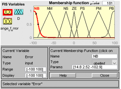
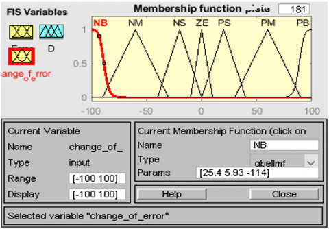
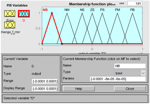
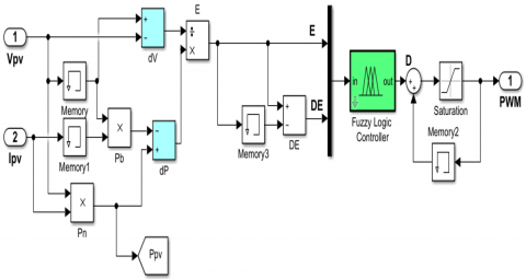
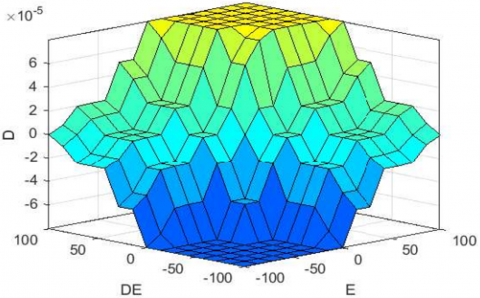
The arrangement for the fuzzy subsets with two input variables, along with one output, which can be changed to appropriately use the system, and the membership function's shape as displayed in Figure 9. The PV panel's current, along with voltage, are the two inputs for the MPPT topology setup shown in Figure 10. The efficiency of the system is expressed by the duty cycle of the DC-DC boost converter. The relationship between the inputs and final results of the fuzzy controller can be described as a surface functioning as shown in Figure 11, which is a diagram in three dimensions. Undoubtedly, the functional surface is roughly smooth, enhancing a stable state of the fuzzy system.
(a) Input (E)
(b) Input (CE)
(c) Output (D)
Figure 9. The membership functions of the three variables
Figure 10. Circuit schematic for FLC
Figure 11. Surface function of the suggested FLC for MPPT of the PV system
In this section, the reported results of the quality and efficiency variables of the power will also be established to demonstrate the efficacy of the control techniques applied to improve the hybrid microgrid's power quality in Figure 2. As previously mentioned, MATLAB software is used for all simulations, and the controller has been inspected. Table 1 presents the system parameters. The following results confirm the efficacy of the controlling methods employed to enhance the quality of the power across the proposed HMG system.
5.1 Simulation results of different MPPT control methods for a PV system
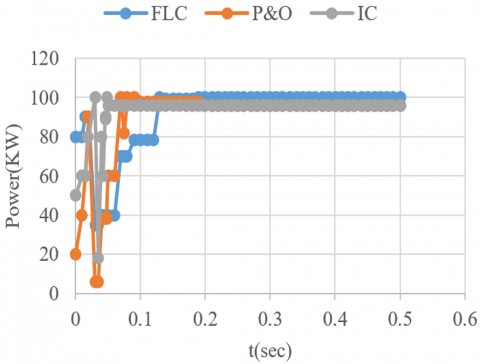
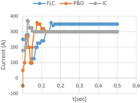
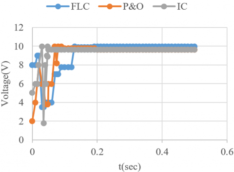
A dynamic representation of a solar electricity system using the controller with fuzzy logic, conventional P&O, and IC algorithm on the solar system as that to MPPT, could be used to analyze the characteristics of the converter, including the voltage of the input, the voltage at the output, in addition to electrical current, power, along efficiency. To determine each algorithm's near to the MPP values, the initial three variables were chosen. The output voltage was selected to confirm that there are apparent oscillations at the output converter, and to ascertain whether an FLC generates a notably higher efficiency, the efficiency value was utilized. This is further demonstrated by the outcomes obtained, which are present in the accompanying Figure 12 and Table 3.
(a) Power
(b) Current
(c) Voltage
Table 3. Comparison of different methods for obtaining MPPT
|
Control |
Power (kw) |
Voltage (V) |
Current (A) |
Efficiency % |
Settling Time (s) |
|
FLC |
99.68 |
283 |
351 |
99.84 |
0.17 |
|
IC |
94.52 |
310 |
304 |
94.33 |
0.19 |
|
P&O |
93.34 |
312 |
299 |
93.15 |
0.13 |
As demonstrated by the figures above, the FLC approach yields higher efficiency, power, voltage, and current in comparison with both P&O and IC algorithms at the same environmental parameters; nevertheless, FLC takes longer to stabilize. Despite FLC's long settling time compared to other methods, this indicates that the controller reached the correct MPP to provide higher power than the traditional algorithms.
As a result of the efficiency value being more stable, the oscillations are slightly smaller for FLC when they reach the MPP, as is primarily visible in Figure 12(a). To show how beneficial it is at reducing oscillations with MPP under steady-state circumstances. The specific interval's environmental conditions 1000 W/m2 of solar radiation along with a 25°C ambient temperature are identical to the PV panels' test environment, so that the boost converter's voltage, current, and power output should almost exactly correspond for the results of MPP listed in Table 2. This is verified by Figure 12.
Because every research employs a converter with specific characteristics and looks at how PV systems operate under different combinations of ambient temperature and solar irradiation, it is exceedingly difficult to compare the results achieved for the suggested algorithms to those of other research directly. As a result of the work's observation indicating that an elevation-value capacitor, along with a little value inductor, favorably affects the converter's efficiency, after comparing FLC with traditional algorithms, this study indicated that FLC is the best approach, which gives high output power and optimal efficiency for use in the proposed MG system in this study.
5.2 BESS
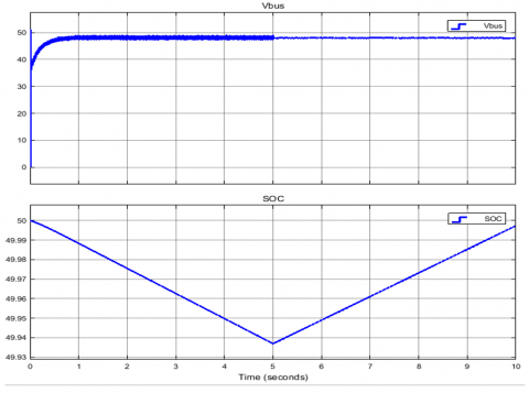
A description of the HMG's battery as having a standard voltage of 384 volts, a current capacity of 2000 Ah, and an initial state of charge rate (SOC) is 50% SOC rate. Since the SOC has been set to 50%. Depending on the battery's condition, charging will occur to the required level when the PV's irradiance is less than 100 W/m2; the battery will start charging at that proportion. Figure 13 shows that the battery was operated in discharge mode for five seconds and the SOC of the battery dropped while maintaining the line voltage of 48V. Moreover, the charge a battery at SOC required to achieve 80% of its capacity at 418 volts. Notice that the SOC for the battery is choice to 50% charged in order to safeguard and ensure it has a long life.
Figure 13. DC-bus and SOC under charge and discharge
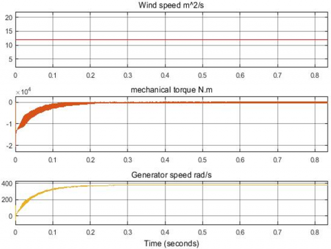
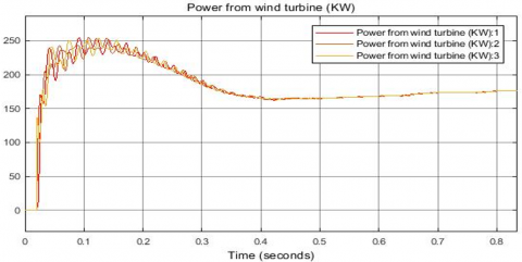
5.3 Simulation results of the wind turbine
Features that enable the wind turbine to generate power in the range of 100 to 600 kW. The blades have a diameter of forty meters. The operating wind speed is between 6 and 40 m/s. Eight PMSG generator poles with a 500-volt output voltage are coupled to an AC-DC-AC converter. Figure 14 illustrates the features of when wind speeds fall between 10 and 15 m2/sec. The figure shows that the mechanical torque is less than zero at first, increases over the course of 0.1 sec, and then remains at that value. Additionally, the figure will show that the wind turbine speed for the generator starts at zero and increases over the course of 0.2 sec, reaching almost 480 rad/sec.
Figure 14. Mechanical torque and speed of the generator and wind
5.4 Simulation results of Hybrid AC/DC Microgrid (HMG)
Renewably sourced electricity is used in this planned hybrid microgrid, including solar (PV) arrays and wind turbine generators (WTG). Here, MATLAB software is used to simulate the microgrid for the purpose of reducing both AC and DC switching to enhance efficiency, and enhancing the quality of the power of the proposed hybrid microgrid. Furthermore, preventing overcharging or excessive discharge of the battery, which could harm them and shorten their usable lives, is another essential component of the control system on a hybrid microgrid.
5.4.1 Simulation result of PV-side
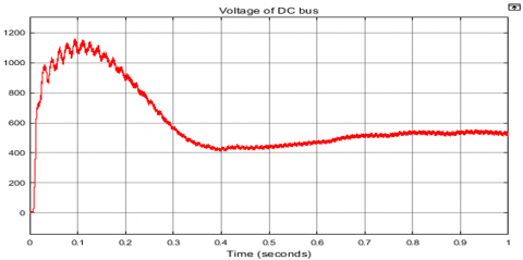
When using FLC with an MPPT controller is give best outcomes are achieved with results found from using the two conventional algorithms, IC and P&O, as shown in Figure 15 displays supplying the DC load with the voltage from the DC bus with a slight ripple under constant temperature (25℃) and variable irradiance at the optimal duty cycle to the converter from the PV system. It is noticeable that the output DC voltage becomes almost stable after a short period of time is 0.35 seconds from the start time. It is necessary to deliver the DC load at 500 V, that being the electrical voltage across the DC bus.
Figure 15. Voltage of DC bus
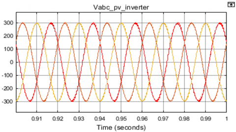
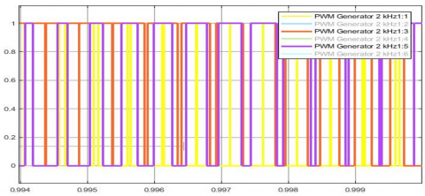
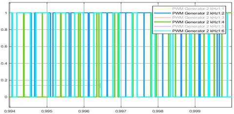
Figures 16 and 17 show the voltage and current that exit the PV system and connect to the grid through an inverter that needs six pulses to change the DC power to AC voltage. Next, the VSC control is employed for the purpose of maintaining the voltage 380 × √2 ≈ 540 V throughout the DC link. The inverter pulses that produced these outcomes are displayed in Figure 18(a) shows the PWM output of switching (1, 3, and 5) and Figure 18(b) shows the PWM output of switching (2, 4, and 6) that represented after converting the voltage from AC to DC, it is employed to supply power to the AC load through a DC/AC the bus. by level-stabilizing and converting the AC output voltage from the DC bus to AC.
Figure 16. Voltage of DC-AC converter PV-side
Figure 17. Current of DC-AC converter PV-side
(a) Output of switching (1, 3, and 5)
(b) Output of switching (2, 4, and 6)
Figure 18. PWM of VSC controller PV-side
5.4.2 Simulation result of the WT-side
Considering wind speed affects both the frequency and speed of WTG, variations in wind speed will have an impact on the stability of the results.
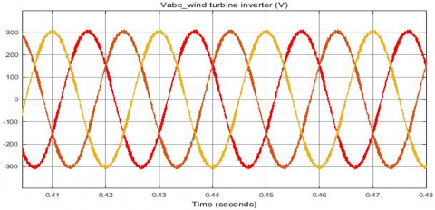
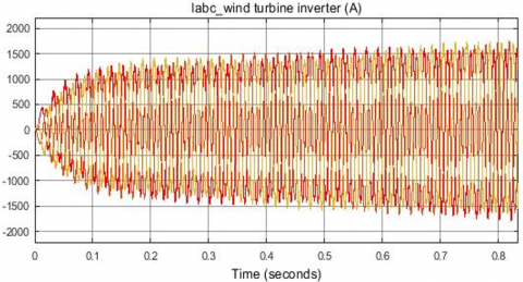
The three-phase electric currents, voltages, and electric power delivered across the converter are displayed in Figure 18. That is, six pulses are required for the AC-DC-AC conversion to convert the DC voltage to the voltage of AC. After that, VSC control is utilized to keep the voltage at the required level (380 V, 50 Hz) regularly. The output three-phase voltage wave forms in Figure 19(a) demonstrate that they are stable, identical in value, and have the exact same frequency. However, the current levels will start to rise steadily and eventually stabilize at roughly constant values. In Figure 19(b), as indicated. Lastly, as seen in Figure 19(c), the power of the AC-DC-AC WT converter starts to rise and fluctuate a short while after zero. Then, the power waveforms start to stabilize and remain steady and stable. Even with variations in wind speed, the WT-system continues to provide steady power and voltage after a brief period of time from the beginning of generation. That is because using a pitch angle regulator to control the rotating speed through the usage of a PI controller has both advantages and disadvantages. Additionally, the WT-system-connected VSC has a significant impact on maintaining these variables' constant values following brief oscillations before reaching stability.
(a) Voltage
(b) Current
(c) Power
Figure 19. The WT-side AC-DC-AC converter's
5.4.3 Simulation result of HMG system
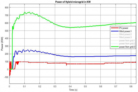
As depicted in Figure 20, the evaluation looked at the changes in WTG and PV generation power based on the results. Here, the power results for the wind and solar systems show that their power is higher than that of the HMG system, which provides a higher power value of about 600 kW. The power results also show that the power of the network is efficient in producing electricity, as it starts to stabilize after 0.3 seconds.
Figure 20. Power taken from PV, WT and unity grid
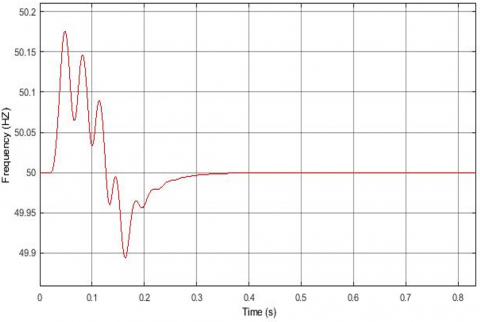
As seen in Figure 21, the frequency of all buses in this assessment gave findings that showed a distortion at first. It then enters a steady condition, which lasts for 0-0.3 seconds, or the time it takes to reach stability at (50 Hz). And also see that, as is apparent, there is little distortion from the start and small frequency variation, which is regarded as an advantageous feature of the electrical circuit's general design.
Figure 21. Frequency of all buses
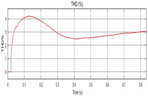
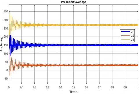
Figure 22 illustrates the detection of total harmonic distortion (THD) in the line-line voltage signal along the transmission lines of the HMG system. THD occurs when a sinusoidal signal is fed to the inverter, causing it to cut and distort. THD starts at zero, after that it increases and then slows down for a period time is 0.7 seconds before stabilizing and reaching to value of roughly 0.03. As illustrated in Figure 23, it takes some time before stabilizing at 120 degrees associated with a phase difference for the output voltage along the transmission lines of the HMG system in less than 0.1 seconds.
Figure 22. THD of L-L voltage
Figure 23. Phase shift between 3 phases on all buses
This paper introduces the idea of an HMG. That's for presenting hybrid microgrid control techniques that can minimize AC and DC switching, thereby increasing the hybrid grid's efficiency. This will allow for an analysis of the microgrid system's operation in the management arrangement, an important consideration. keeping the network stable in a variety of operational environments. For investigational purposes, the system was simulated within the MATLAB environment.
Design and control the proposed hybrid microgrid has various control strategies, in the PV system the which examines the three methods as MPPT under the same Circumstances, where the traditional methods were used (P&O and IC) algorithms, and used the FLC method. Based on the outcomes of the simulation, the FLC approach proved to be more effective when applied to a boost conversion. So, the PV system has improved the energy system's efficiency under ideal conditions to 99.84% and enhanced the quality of power to provide 99.68 kW at steady state. These improvements boost the energy production of the system while also increasing its power and general efficacy. A battery energy system that was controlled by a PI control structure received a steady DC bus voltage from the PV system's output, to determine the maximum value of the current and voltage during both the charging and discharge states of the battery's operation. For the purpose of identifying their appropriate values for the two-mode states of the battery. This indicates that a battery is in a drained state when the PV energy irradiation is less than 100 W/m2. In wind system was adjust the pitch angle control by PI controller is used on wind turbine to eliminate problems caused by changes in wind speed hat lead to changes in electrical energy production and thus affect its production, and control mechanism employed by VSR, which adjusted the PI controller's parameters using the BFO algorithm, which regulates the real and reference dc-link voltage when the boost converter's DC/bus output needs to be kept constant at a specific level. Additionally, apply the same method to the AC grid line in order to maintain the necessary voltage across the line. Furthermore, the inverter's power factor is kept at unity consistently. According to the simulation results, it shows the effective in meeting the main goals of these control techniques, maintaining voltage stability, enhancing the quality of power, and transferring power seamlessly between AC and DC links using these methods of control on all sources in the proposed hybrid MG. improving the quality of the electricity and protecting the battery from excessive charging or discharging, which can damage it and shorten its useful life. So, these important objectives have been achieved.
In the future, MGs present a desirable option for DG unit integration into the Smart Grid, which might reduce reliance on fossil fuels and boost grid efficiency. Challenges with the intended HMG study, reliable control methods were employed to address the change in climatic circumstances that impact the generation of clean energy, such as solar and wind energy.
This work is supported by the Southern Technical University, College of Technical Engineering, Basrah, and the Department of Electrical Technology Engineering.
|
DGs |
Distributed generators |
|
MG |
Microgrid |
|
HMG |
Hybrid AC/DC Microgrid |
|
PV |
Photovoltaic |
|
WECS |
Wind energy control system |
|
PMSG |
Permanent magnet synchronous generator |
|
SFIG |
Single phase induction generator |
|
VSC |
Voltage source converter |
|
BFO |
Bacteria foraging optimization |
|
MPPT |
Maximum power point tracking |
|
FLC |
Fuzzy logic controller |
|
IC |
Incremental conductance algorithm |
|
P&O |
Perturbation and observation algorithm |
|
PI |
Proportional integral controller |
|
ESS |
Energy storage system |
|
BBDC |
Buck boost bidirectional converter |
[1] Olivares, D.E., Mehrizi-Sani, A., Etemadi, A.H., Cañizares, C.A., et al. (2014). Trends in microgrid control. IEEE Transactions on Smart Grid, 5(4): 1905-1919. https://doi.org/10.1109/TSG.2013.2295514
[2] Lasseter, R.H. (2002). Microgrids. In 2002 IEEE Power Engineering Society Winter Meeting. Conference Proceedings (Cat. No.02CH37309), New York, USA, pp. 305-308. https://doi.org/10.1109/PESW.2002.985003
[3] Planas, E., Andreu, J., Gárate, J.I., De Alegría, I.M., et al. (2015). AC and DC technology in microgrids: A review. Renewable and Sustainable Energy Reviews, 43: 726-749. https://doi.org/10.1016/j.rser.2014.11.067
[4] Gutiérrez-Oliva, D., Colmenar-Santos, A., Rosales-Asensio, E. (2022). A review of the state of the art of industrial microgrids based on renewable energy. Electronics, 11(7): 1002. https://doi.org/10.3390/electronics11071002
[5] Baimel, D., Belikov, J., Guerrero, J.M., Levron, Y. (2017). Dynamic modeling of networks, microgrids, and renewable sources in the dq0 reference frame: A survey. IEEE Access, 5: 21323-21335. https://doi.org/10.1109/ACCESS.2017.2758523
[6] Kaur, A., Kaushal, J., Basak, P. (2016). A review on microgrid central controller. Renewable and Sustainable Energy Reviews, 55: 338-345. https://doi.org/10.1016/j.rser.2015.10.141
[7] García Vera, Y.E., Dufo-López, R., Bernal-Agustín, J.L. (2019). Energy management in microgrids with renewable energy sources: A literature review. Applied Sciences, 9(18): 3854. https://doi.org/10.3390/app9183854
[8] Shahzad, S., Abbasi, M.A., Ali, H., Iqbal, M., et al. (2023). Possibilities, challenges, and future opportunities of microgrids: A review. Sustainability, 15(8): 6366. https://doi.org/10.3390/su15086366
[9] Gabbar, H.A., Abdelsalam, A.A. (2014). Microgrid energy management in grid-connected and islanding modes based on SVC. Energy Conversion and Management, 86: 964-972. https://doi.org/10.1016/j.enconman.2014.06.070
[10] Hossain, M.A., Pota, H.R., Issa, W., Hossain, M.J. (2017). Overview of AC microgrid controls with inverter-interfaced generations. Energies, 10(9): 1300. https://doi.org/10.3390/en10091300
[11] Andishgar, M.H., Gholipour, E., Hooshmand, R.A. (2017). An overview of control approaches of inverter-based microgrids in islanding mode of operation. Renewable and Sustainable Energy Reviews, 80: 1043-1060. https://doi.org/10.1016/j.rser.2017.05.267
[12] Ntombela, M., Musasa, K., Moloi, K. (2023). A comprehensive review of the incorporation of electric vehicles and renewable energy distributed generation regarding smart grids. World Electric Vehicle Journal, 14(7): 176. https://doi.org/10.3390/wevj14070176
[13] Subramanian, V., Indragandhi, V., Kuppusamy, R., Teekaraman, Y. (2021). Modeling and analysis of PV system with fuzzy logic MPPT technique for a DC microgrid under variable atmospheric conditions. Electronics, 10(20): 2541. https://doi.org/10.3390/electronics10202541
[14] Hernández-Ocaña, B., Hernández-Torruco, J., Chávez-Bosquez, O., Calva-Yáñez, M.B., et al. (2019). Bacterial foraging-based algorithm for optimizing the power generation of an isolated microgrid. Applied Sciences, 9(6): 1261. https://doi.org/10.3390/app9061261
[15] Tayab, U.B., Roslan, M.A.B., Hwai, L.J., Kashif, M. (2017). A review of droop control techniques for microgrid. Renewable and Sustainable Energy Reviews, 76: 717-727. https://doi.org/10.1016/j.rser.2017.03.028
[16] Anandhakumar, G., Venkateshkumar, M., Shankar, P. (2013). Intelligent controller based MPPT method for the Photovoltaic power system. In 2013 International Conference on Human Computer Interactions (ICHCI), Chennai, India, pp. 1-6. https://doi.org/10.1109/ICHCI-IEEE.2013.6887790
[17] Martin-Martínez, F., Sánchez-Miralles, A., Rivier, M. (2016). A literature review of Microgrids: A functional layer based classification. Renewable and Sustainable Energy Reviews, 62: 1133-1153. https://doi.org/10.1016/j.rser.2016.05.025
[18] Mirsaeidi, S., Dong, X.Z., Said, D.M. (2018). Towards hybrid AC/DC microgrids: Critical analysis and classification of protection strategies. Renewable and Sustainable Energy Reviews, 90: 97-103. https://doi.org/10.1016/j.rser.2018.03.046
[19] Lamichhane, A., Zhou, L., Yao, G., Luqman, M. (2019). LCL filter based grid-connected photovoltaic system with battery energy storage. In 2019 14th IEEE Conference on Industrial Electronics and Applications (ICIEA), Xi'an, China, pp. 1569-1574. https://doi.org/10.1109/ICIEA.2019.8834271
[20] Jordehi, A.R. (2016). Maximum power point tracking in photovoltaic (PV) systems: A review of different approaches. Renewable and Sustainable Energy Reviews, 65: 1127-1138. https://doi.org/10.1016/j.rser.2016.07.053
[21] Elgendy, M.A., Atkinson, D.J., Zahawi, B. (2016). Experimental investigation of the incremental conductance maximum power point tracking algorithm at high perturbation rates. IET Renewable Power Generation, 10(2): 133-139. https://doi.org/10.1049/iet-rpg.2015.0132
[22] Eltamaly, A.M. (2018). Chapter 4 – Performance of MPPT techniques of photovoltaic systems under normal and partial shading conditions. In Advances in Renewable Energies and Power Technologies Volume 1: Solar and Wind Energies. Elsevier, pp. 115-161. https://doi.org/10.1016/b978-0-12-812959-3.00004-6
[23] Unamuno, E., Barrena, J.A. (2015). Hybrid AC/DC microgrids—Part I: Review and classification of topologies. Renewable and Sustainable Energy Reviews, 52: 1251-1259. https://doi.org/10.1016/j.rser.2015.07.194
[24] Al-Quraan, A., Al-Qaisi, M. (2021). Modelling, design and control of a standalone hybrid PV-wind micro-grid system. Energies, 14(16): 4849. https://doi.org/10.3390/en14164849
[25] Rathore, A., Patidar, N.P. (2019). Reliability assessment using probabilistic modelling of pumped storage hydro plant with PV-Wind based standalone microgrid. International Journal of Electrical Power & Energy Systems, 106: 17-32. https://doi.org/10.1016/j.ijepes.2018.09.030
[26] Al-Masri, H.M.K., Al-Quraan, A., AbuElrub, A., Ehsani, M. (2019). Optimal coordination of wind power and pumped hydro energy storage. Energies, 12(22): 4387. https://doi.org/10.3390/en12224387
[27] Deng, X.F., Yang, J., Sun, Y., Song, D.R., et al. (2020). An effective wind speed estimation based extended optimal torque control for maximum wind energy capture. IEEE Access, 8: 65959-65969. https://doi.org/10.1109/ACCESS.2020.2984654
[28] Al-Quraan, A., Al-Mahmodi, M., Radaideh, A., Al-Masri, H.M.K. (2020). Comparative study between measured and estimated wind energy yield. Turkish Journal of Electrical Engineering and Computer Sciences, 28: 2926-2939. https://doi.org/10.3906/elk-2002-85
[29] Shafiei, A., Dehkordi, B.M., Kiyoumarsi, A., Farhangi, S. (2017). A control approach for a small-scale PMSG-based WECS in the whole wind speed range. IEEE Transactions on Power Electronics, 32(12): 9117-9130. https://doi.org/10.1109/tpel.2017.2655940
[30] Mousa, H.H.H., Youssef, A.R., Mohamed, E.E.M. (2020). Optimal power extraction control schemes for five-phase PMSG based wind generation systems. Engineering Science and Technology, an International Journal, 23(1): 144-155. https://doi.org/10.1016/j.jestch.2019.04.004
[31] Madrigal, G.A.M., Cuevas, K.G., Hora, V., Jimenez, K.M., et al. (2019). Fuzzy logic-based maximum power point tracking solar battery charge controller with backup stand-by AC generator. Indonesian Journal of Electrical Engineering and Computer Science, 16(1): 136-146. https://doi.org/10.11591/ijeecs.v16.i1.pp136-146
[32] Essamudin, E.A. (2015). A novel approach of bacteria-foraging optimized controller for DC motor and centrifugal pump set fed from photo-voltaic array. Journal of Next Generation Information Technology, 6(1): 21-31.
[33] Das, S., Biswas, A., Dasgupta, S., Abraham, A. (2009). Bacterial foraging optimization algorithm: Theoretical foundations, analysis, and applications. In Foundations of Computational Intelligence Volume 3: Global Optimization. Springer, Berlin, pp. 23-55. https://doi.org/10.1007/978-3-642-01085-9_2
[34] Datta, T., Misra, I., Mangaraj, B., Imtiaj, S. (2008). Improved adaptive bacteria foraging algorithm in optimization of antenna array for faster convergence. Progress in Electromagnetics Research C, 1: 143-157. http://doi.org/10.2528/PIERC08011705
[35] Heo, S.Y., Kim, M.K., Choi, J.W. (2015). Hybrid intelligent control method to improve the frequency support capability of wind energy conversion systems. Energies, 8(10), 11430-11451. https://doi.org/10.3390/en81011430
[36] Hemanand, T., Subramaniam, N.P., Venkateshkumar, M. (2018). Comparative analysis of intelligent controller based microgrid integration of hybrid PV/wind power system. Journal of Ambient Intelligence and Humanized Computing, 1-20. https://doi.org/10.1007/s12652-018-0961-6
[37] Hohm, D.P., Ropp, M.E. (2000). Comparative study of maximum power point tracking algorithms using an experimental, programmable, maximum power point tracking test bed. In Conference Record of the Twenty-Eighth IEEE Photovoltaic Specialists Conference - 2000 (Cat. No.00CH37036), Anchorage, AK, USA, pp. 1699-1702. https://doi.org/10.1109/PVSC.2000.916230